Table of Contents
Advertisement
Quick Links
Advertisement
Table of Contents

Related Manuals for FLIR Extech Instruments MG302


Summary of Contents for FLIR Extech Instruments MG302
- Page 1 User's Guide Wireless TRMS Multimeter and Insulation Tester Model MG302...
- Page 2 Introduction Congratulations on your purchase of the MG300 True RMS MultiMeter Insulation Resistance Tester. This meter measures AC/DC Voltage, AC/DC Current, Resistance, Capacitance, Frequency (electrical & electronic), Duty Cycle, Diode Test, Insulation Resistance, and Continuity plus Thermocouple Temperature. The MG300 can store and recall measurement data and features a waterproof, rugged design for heavy duty use.
-
Page 3: Safety Instructions
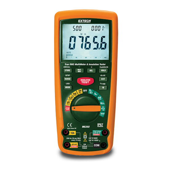
SAFETY INSTRUCTIONS This meter has been designed for safe use, but must be operated with caution. The rules listed below must be carefully followed for safe operation. NEVER apply voltage or current to the meter that exceeds the specified maximum: Input Protection Limits Function Maximum Input... - Page 4 Controls and Jacks 1. 40,000 count LCD display 2. MAX/MIN ( - ) button 3. STORE (<RECALL) button 4. RANGE(SETUP) button 5. INSULATION TEST button 6. MODE button 7. Function switch 8. 10A input jack 9. mA, µA, Insulation (-) jack 10.
-
Page 5: Dc Voltage Measurements
Operating Instructions WARNING: Risk of electrocution. High-voltage circuits, both AC and DC, are very dangerous and should be measured with great care. ALWAYS turn the function switch to the OFF position when the meter is not in use. If “OL” appears in the display during a measurement, the value exceeds the range you have selected. -
Page 6: Mv Voltage Measurements
mV VOLTAGE MEASUREMENTS CAUTION: Do not measure mV voltages if a motor on the circuit is being switched ON or OFF. Large voltage surges may occur that can damage the meter. Set the function switch to the mV position. Press the MODE button to indicate “DC” or “AC” In AC mode, press and hold EXIT for two seconds to select ”AC+DC”... -
Page 7: Ac Current (Frequency, Duty Cycle) Measurements
AC CURRENT (FREQUENCY, DUTY CYCLE) MEASUREMENTS CAUTION: Do not make 20A current measurements for longer than 30 seconds. Exceeding 30 seconds may cause damage to the meter and/or the test leads. Insert the black test lead banana plug into the negative COM jack. For current measurements up to 4000µA AC, set the function switch to the µA position and insert the red test lead banana plug into the µA/mA jack. -
Page 8: Continuity Check
CONTINUITY CHECK WARNING: To avoid electric shock, never measure continuity on circuits or wires that have voltage on them. Set the function switch to the Ω CAP position. Insert the black lead banana plug into the negative COM jack. Insert the red test lead banana plug into the positive Ω Ω Ω Ω jack. Press the MODE button to indicate“... -
Page 9: Temperature Measurements
TEMPERATURE MEASUREMENTS Set the function switch to the Temp position. Insert the Temperature Probe into the input jacks, making sure to observe the correct polarity. Press the MODE button to indicate “ºF” or “ºC” Touch the Temperature Probe head to the part whose temperature you wish to measure. -
Page 10: Insulation Resistance Measurements
% 4 – 20mA MEASUREMENTS Set up and connect the meter as described for DC mA measurements. Set the rotary function switch to the 4-20mA% position. The meter will display loop current as a % with 0mA=-25%, 4mA=0%, 20mA=100%, and 24mA=125%. -
Page 11: Autoranging/Manual Range Selection
AUTORANGING/MANUAL RANGE SELECTION When the meter is first turned on, it automatically enters the AUTO RANGE mode. This automatically selects the best range for the measurements being made and is generally the best mode for most measurements. For measurement situations requiring that a range be manually selected, perform the following: Press the RANGE key. -
Page 12: Display Backlight
DISPLAY BACKLIGHT Press the key to switch the backlight on. The backlight will automatically switch off after the SET time has expired. Press the EXIT button to exit the backlight on mode. HOLD The hold function freezes the reading in the display. Press the HOLD key momentarily to activate or to exit the HOLD function. -
Page 13: Alarm Limits
PC WIRELESS COMMUNICATION Install and launch the PC software (refer to the HELP utility contained in the software for more details) Press and Hold the backlight/USB button for two seconds to enter RF wireless transmit mode The RF icon will appear on the display When communication is established, the RF icon on the display will blink and the LED indicator on the receiver will blink Once per second, the data will be displayed on the PC screen (plotted on the graph and... -
Page 14: Battery Installation
Maintenance WARNING: To avoid electric shock, disconnect the test leads from any source of voltage before removing the back cover or the battery or fuse covers. WARNING: To avoid electric shock, do not operate your meter until the battery and fuse covers are in place and fastened securely. -
Page 15: Replacing The Fuses
REPLACING THE FUSES WARNING: To avoid electric shock, disconnect the test leads from any source of voltage before removing the meter cover. 1. Disconnect the test leads from the meter. 2. To replace the 500mA fuse only, remove the battery cover (four screws); the 500mA fuse will be visible and accessible. -
Page 16: Specifications
Specifications Function Range Resolution Accuracy DC Voltage 400mV 0.01mV 0.0001V ±(0.06% reading + 4 digits) 0.001V 400V 0.01V ±(0.1% reading + 5 digits) 1000V 0.1V AC Voltage 400mV 0.1mV ±(1.0% reading + 7 digits) (AC+DC) 0.001V 50 to 1000Hz 0.01V ±(1.0% reading +5 digits) 400V 0.1V... - Page 17 Function Range Resolution Accuracy ±(0.3% reading + 9 digits) Resistance 400Ω 0.01Ω 4kΩ 0.0001kΩ 40kΩ 0.001kΩ ±(0.3% reading + 4 digits) 400kΩ 0.01kΩ 4MΩ 0.0001MΩ ±(2.0% reading + 10 digits) 40MΩ 0.001MΩ Capacitance 40nF 0.001nF ±(3.5% reading + 40 digits) 400nF 0.01nF 4µF...
- Page 18 Meg OHMS Terminal Voltage Range Resolution Accuracy Test current Short circuit current 125V (0%~+10%) 0.125~4.000 MΩ 0.001MΩ +(2%+10) 1mA @ load ≤1mA 125kΩ 4.001~40.00 MΩ 0.01MΩ +(2%+10) 40.01~400.0 MΩ 0.1MΩ +(4%+5) 400.1~4000 MΩ 1MΩ +(5%+5) 250V (0%~+10%) 0.250~4.000 MΩ 0.001MΩ +(2%+10) 1mA @ load ≤1mA...
- Page 19 EN61010-1 and IEC61010-1 2 Edition (2001) to Category IV 600V and Category III 1000V; Pollution Degree 2. Copyright © 2011 Extech Instruments Corporation (a FLIR company) All rights reserved including the right of reproduction in whole or in part in any form. www.extech.com...
Need help?
Do you have a question about the Extech Instruments MG302 and is the answer not in the manual?
Questions and answers