
Related Manuals for FLIR EXTECH INSTRUMENTS EX520


Summary of Contents for FLIR EXTECH INSTRUMENTS EX520
- Page 1 99 Washington Street User's Guide Melrose, MA 02176 Phone 781-665-1400 Toll Free 1-800-517-8431 Visit us at www.TestEquipmentDepot.com True RMS Industrial Multimeter Extech EX520...
- Page 2 Introduction Congratulations on your purchase of the Extech EX520 True RMS Autoranging Multimeter. This meter measures AC/DC Voltage, AC/DC Current, Resistance, Capacitance, Frequency (electrical & electronic), Diode Test, and Continuity plus Thermocouple Temperature. It features a rugged design for heavy duty use. Proper use and care of this meter will provide many years of reliable service.
- Page 3 CAUTIONS • Improper use of this meter can cause damage, shock, injury or death. Read and understand this user manual before operating the meter. • Always remove the test leads before replacing the battery or fuses. • Inspect the condition of the test leads and the meter itself for any damage before operating the meter.
-
Page 4: Safety Instructions
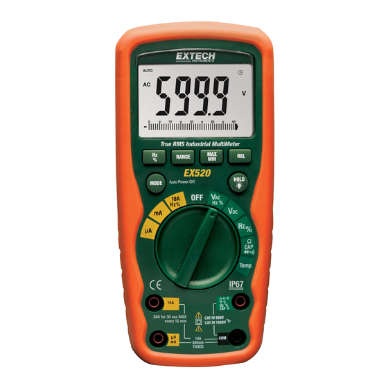
SAFETY INSTRUCTIONS This meter has been designed for safe use, but must be operated with caution. The rules listed below must be carefully followed for safe operation. NEVER apply voltage or current to the meter that exceeds the specified maximum: Input Protection Limits Function Maximum Input... - Page 5 Controls and Jacks 1. 6,000 count LCD 2. RANGE button 3. Hz and % button 4. Mode button 5. Function switch 6. mA, µA and 10A input jacks 7. COM input jack 8. Positive input jack 9. HOLD and Backlight button 10.
-
Page 6: Dc Voltage Measurements
Operating Instructions WARNING: Risk of electrocution. High-voltage circuits, both AC and DC, are very dangerous and should be measured with great care. 1. ALWAYS turn the function switch to the OFF position when the meter is not in use. 2. If “OL” appears in the display during a measurement, the value exceeds the range you have selected. -
Page 7: Dc Current Measurements
DC CURRENT MEASUREMENTS CAUTION: Do not make 20A current measurements for longer than 30 seconds. Exceeding 30 seconds may cause damage to the meter and/or the test leads. 1. Insert black test lead banana plug into the negative COM jack. 2. -
Page 8: Resistance Measurements
RESISTANCE MEASUREMENTS WARNING: To avoid electric shock, disconnect power to the unit under test and discharge all capacitors before taking any resistance measurements. Remove the batteries and unplug the line cords. 1. Set the function switch to the green Ω CAP position. -
Page 9: Temperature Measurements
TEMPERATURE MEASUREMENTS 1. Set the function switch to the green Temp position. 2. Insert the Temperature Probe into the input jacks, making sure to observe the correct polarity. 3. Press the MODE button to indicate ºF or ºC 4. Touch the Temperature Probe head to the part whose temperature you wish to measure. -
Page 10: Autoranging/Manual Range Selection
AUTORANGING/MANUAL RANGE SELECTION When the meter is first turned on, it automatically goes into Autoranging. This automatically selects the best range for the measurements being made and is generally the best mode for most measurements. For measurement situations requiring that a range be manually selected, perform the following: 1. -
Page 11: Maintenance
Maintenance WARNING: To avoid electric shock, disconnect the test leads from any source of voltage before removing the back cover or the battery or fuse covers. WARNING: To avoid electric shock, do not operate your meter until the battery and fuse covers are in place and fastened securely. -
Page 12: Replacing The Fuses
WARNING: To avoid electric shock, do not operate the meter until the battery cover is in place and fastened securely. NOTE: If your meter does not work properly, check the fuses and batteries to make sure that they are still good and that they are properly inserted. F1 F2 REPLACING THE FUSES WARNING: To avoid electric shock, disconnect the test leads from any source of voltage... -
Page 13: Specifications
Specifications Function Range Resolution Accuracy DC Voltage 600mV 0.1mV 0.001V ±(0.09% reading + 2 digits) 0.01V 600V 0.1V 1000V AC Voltage 50 to 60Hz 40Hz to 1KHz 0.001V 0.01V ±(1.0% reading + 3 dgts) ±(2.0% reading + 3 dgts) 600V 0.1V 1000V All AC voltage ranges are specified from 5% of range to 100% of range... - Page 14 Function Range Resolution Accuracy Resistance 600Ω 0.1Ω 6kΩ 0.001kΩ ±(0.3% reading + 4 digits) 60kΩ 0.01kΩ 600kΩ 0.1kΩ 6MΩ 0.001MΩ ±(0.3% reading + 20 digits) 40MΩ 0.01MΩ Capacitance 60nF 0.01nF 600nF 0.1nF ±(3.5% reading + 4 digits) 6μF 0.001μF 60μF 0.01μF 600μF 0.1μF...
- Page 15 Enclosure Double molded, waterproof (IP67) Shock (Drop Test) 6.5 feet (2 meters) Diode Test Test current of 0.9mA maximum, open circuit voltage 2.8V DC typical Continuity Check Audible signal will sound if the resistance is less than 100Ω (approx.), test current <0.35mA Temperature Sensor Requires type K thermocouple Input Impedance...
Need help?
Do you have a question about the EXTECH INSTRUMENTS EX520 and is the answer not in the manual?
Questions and answers