Table of Contents
Advertisement
Advertisement
Table of Contents

Related Manuals for FLIR DM166


Summary of Contents for FLIR DM166
- Page 1 USER MANUAL FLIR MODEL DM166 Thermal Imaging Digital MultiMeter with IGM...
-
Page 2: Table Of Contents
6.10 Resistance Measurements 6.11 Continuity Test 6.12 Diode Test 6.13 Capacitance Measurements 6.14 Type K Temperature Measurements 6.15 Current and Frequency Measurements (A, mA, µA) 6.15.1 Test Lead Current Measurements (A, mA, and µA) FLIR DM166 USER MANUAL Document Identifier: DM166-en-US_AA... - Page 3 8. MAINTENANCE 8.1 Cleaning and Storage 8.2 Battery Replacement 8.3 Fuse Replacement 8.4 Disposal of Electronic Waste 9. SPECIFICATIONS 9.1 General specifications 9.2 Thermal Imaging Specifications 9.3 Electrical Specifications 10. TECHNICAL SUPPORT 11. WARRANTIES FLIR DM166 USER MANUAL Document Identifier: DM166-en-US_AA...
-
Page 4: Advisories
1. Advisories 1.1 Copyright © 2017, FLIR Systems, Inc. All rights reserved worldwide. No parts of the software including source code may be reproduced, transmitted, transcribed or translated into any language or computer language in any form or by any means, electronic, magnetic, optical, manual or otherwise, without the prior written permission of FLIR Systems. -
Page 5: Safety
Before operating the device, you must read, understand, and follow all instructions, dangers, warnings, cautions, and notes. FLIR Systems reserves the right to discontinue models, parts or accessories, and other items, or to change specifications at any time without prior notice. ... - Page 6 This symbol, adjacent to a terminal, indicates that, under normal use, hazardous voltages may be present. Double insulation. UL listing is not an indication or a verification of the accuracy of the meter FLIR DM166 USER MANUAL Document Identifier: DM166-en-US_AA...
-
Page 7: Introduction
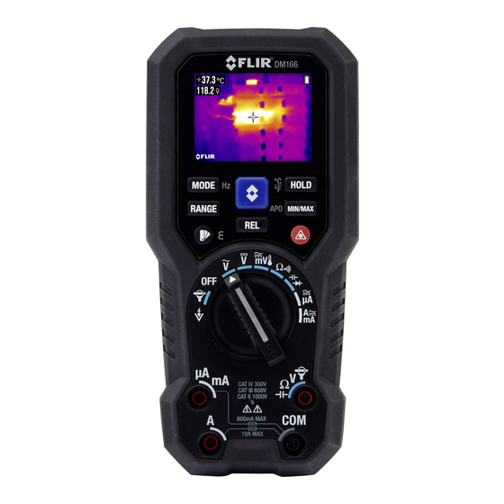
3. Introduction Thank you for selecting the FLIR DM166 True RMS Digital MultiMeter with IGM (Infrared Guided Measurement) Thermal Imaging. The DM166 can measure voltage up to 600V AC/DC and includes a VFD function (low pass filter). The thermal imager measures surface temperature, offers adjustable emissivity, and features a laser pointer and cross hairs for precise targeting. -
Page 8: Meter Description And Reference Guide
15. Thermal Image mode button 1. Laser lens 2. Thermal imaging lens 3. Test Lead holder mounts 4. Tripod mount 5. Tilt stand 6. Battery/Fuse compartment 7. Battery/Fuse door lock Fig. 4-2 Rear View FLIR DM166 USER MANUAL Document Identifier: DM166-en-US_AA... -
Page 9: Function Switch Positions
Measure µA current through the probe inputs. Use the MODE button to select AC or DC. Measure current through the probe inputs (A or mA). Use the MODE button to select AC or DC. Fig. 4-3 Rotary Function Switch FLIR DM166 USER MANUAL Document Identifier: DM166-en-US_AA... -
Page 10: Function Buttons
AC mV < > Frequency (long press) Resistance < > Continuity (short press) Capacitance < > Diode (short press) ACµA < > DCµA (short press) AC < > DC (short press); ACA/ACmA < > Frequency (long press) FLIR DM166 USER MANUAL Document Identifier: DM166-en-US_AA... -
Page 11: Display Icons And Status Indicators
Relative mode (available in DMM and Thermal Image mode) Ԑ Emissivity setting Battery status AC current or voltage DC current or voltage Flex Clamp or standard clamp adaptor direct input Continuity mode Resistance mode FLIR DM166 USER MANUAL Document Identifier: DM166-en-US_AA... -
Page 12: Meter Power
3. Long press the APO button to exit 4. The last APO selection saved becomes the default APO time 5. The DM166 has an ‘intelligent’ APO feature where the meter will not power down if any of the following conditions exist: ... -
Page 13: Multimeter Operation
‘A’ input terminal with the rotary switch set to the ‘µA’ terminal. In these cases, switch the meter off and correctly connect the test leads before attempting to make measurements. Fig. 6-1 Probe Connection Alert Screens FLIR DM166 USER MANUAL Document Identifier: DM166-en-US_AA... -
Page 14: Out Of Range Warning (Ol)
Connect the test lead holder accessory (optional) to the two slots on the back of the meter (item 3 in Fig. 4-2) and to the tripod mount (item 4 in Fig. 4-2). The test lead holder is ergonomic and protects the thermal imaging and laser pointer lenses. FLIR DM166 USER MANUAL Document Identifier: DM166-en-US_AA... -
Page 15: Voltage (Ac/Dc), Vfd, And Frequency (Hz) Measurements
Hz button. Long press again to return to the voltage measurement. For additional functionality, refer to Section 6.5, MIN- MAX-AVG Mode Section 6.6, Relative Mode. Fig. 6-2(b) DC Voltage Measurements FLIR DM166 USER MANUAL Document Identifier: DM166-en-US_AA... -
Page 16: Non-Contact Voltage Detector
5. When the meter detects a voltage, it beeps and displays a blue bar animation. The tone rate and the bar number will increase relative to the detected voltage. Fig. 6-3 Non-Contact Voltage Detector FLIR DM166 USER MANUAL Document Identifier: DM166-en-US_AA... -
Page 17: Resistance Measurements
7. Short press the HOLD button to freeze/unfreeze the displayed reading. 8. For additional functions, see Section 6.5, MIN-MAX-AVG Mode Section 6.6, Relative Mode. Fig. 6-4 Resistance and Continuity Measurements FLIR DM166 USER MANUAL Document Identifier: DM166-en-US_AA... -
Page 18: Continuity Test
OL (overload) in the opposite direction, the component is good. If the measurement is 0V in both directions (shorted) or OL in both directions (open), the component is bad. Fig. 6-5 Diode Test FLIR DM166 USER MANUAL Document Identifier: DM166-en-US_AA... -
Page 19: Capacitance Measurements
Section 6.5, MIN-MAX-AVG Mode Section 6.6, Relative Mode. Fig. 6-6 Capacitance Measurements Note: For very large capacitance values, it may take several minutes for the measurement to settle and the final reading to stabilize. FLIR DM166 USER MANUAL Document Identifier: DM166-en-US_AA... -
Page 20: Type K Temperature Measurements
2. Insert the black probe lead into the negative COM terminal and the red probe lead into one of the following positive terminals: A for high current measurements. mA for lower current measurements. µA for micro-amp measurements FLIR DM166 USER MANUAL Document Identifier: DM166-en-US_AA... - Page 21 7. To see the frequency (Hz) of measured AC current, long press the Hz button; long press again to exit. 8. For additional functionality, refer to Section 6.5, MIN-MAX-AVG Mode Section 6.6, Relative Mode. Fig. 6-9 Current Measurement example FLIR DM166 USER MANUAL Document Identifier: DM166-en-US_AA...
-
Page 22: Flex Clamp Adaptor Current And Frequency Measurements
3. Set the Range of the Flex Clamp Adaptor to match the range of the DM166. 4. Short press the RANGE button to select the range of the DM166 (1, 10, or 100 mv/A, as shown in the upper left corner of the DM166 display). -
Page 23: Igm Tm Thermal Imager Operation
In the Thermal Imaging mode, the user can measure a targeted surface’s temperature. The DM166 accomplishes this by detecting the energy emitted by the surface under test. The DM166 ‘sees’ a thermal image of an area under test in the same manner as with a dedicated thermal imaging device. See Section 7.4, Infrared Energy and Thermal... - Page 24 8. The thermal imager’s FOV (Field of View) is 50 degrees (top view) and 38.6 degrees (side view); see Fig. 7-3 (a) and (b). Fig. 7-2 Distance-to-Spot ratio 30:1 Fig. 7-3 (a) Field of View – side view Fig. 7-3 (b) Field of View - top view FLIR DM166 USER MANUAL Document Identifier: DM166-en-US_AA...
-
Page 25: Using The Multimeter In The Igm Tm Mode
0.90 to 0.94 Paper 0.70 to 0.94 Marble 0.94 Chromium Oxides 0.81 Plaster 0.80 to 0.90 Copper Oxides 0.78 Mortar 0.89 to 0.91 Iron Oxides 0.78 to 0.82 Brick 0.93 to 0.96 Textiles 0.90 FLIR DM166 USER MANUAL Document Identifier: DM166-en-US_AA... -
Page 26: Infrared Energy And Thermal Imaging Overview
All other items are represented as a gray scale value between white and black. The DM166 also offers color images to simulate hot (lighter colors) and cold (darker colors) temperatures. -
Page 27: Maintenance
As with most electronic products, this equipment must be disposed of in an environmentally friendly way, and in accordance with existing regulations for electronic waste. Please contact your FLIR Systems representative for more details. FLIR DM166 USER MANUAL Document Identifier: DM166-en-US_AA... -
Page 28: Specifications
A & mA: 0.4A/1000V DC/AC rms, IR 30kA, F fuse or better A: 11A/1000V DC/AC rms, IR 20kA, F fuse or better V & Auto V: 1100V DC/AC rms mV, Ohm, & others: 1000V DC/AC rms Drop protection: 9.8’(3m) FLIR DM166 USER MANUAL Document Identifier: DM166-en-US_AA... - Page 29 Battery Life: approximately 12 hours ● Battery Type: Energizer L91 Lithium (Li/FeS ) ‘AA’ Battery x 3 Battery Life: approximately 22 hours ● Optional Rechargeable Battery: Li-Polymer; FLIR PN: TA04-KIT Battery Life: approximately 22 hours Power Consumption (typical): 160mA APO Consumption (typical): 200A APO Timing: Five (5) minutes (default), 10 minutes, 20 minutes &...
-
Page 30: Thermal Imaging Specifications
C), or as otherwise specified AC Voltage* RANGE and RESOLUTION Accuracy 50Hz ~ 60Hz 6.000V, 60.00V, 600.0V 0.7% + 3d 45Hz ~ 440Hz 6.000V, 60.00V, 600.0V 2.0% + 3d Input Impedance: 10M, 54pF nominal FLIR DM166 USER MANUAL Document Identifier: DM166-en-US_AA... - Page 31 0.9% + 2d 3) 4) 5) 60.00M 1.5% + 2d Open Circuit Voltage: 1.6VDC typical Constant Test Current: 0.1A Typical Constant Test Current: 0.01A Typical 5%+20d @ >30M, Unspecified @ ambient > 40 FLIR DM166 USER MANUAL Document Identifier: DM166-en-US_AA...
- Page 32 2) <400mA continuous; >400mA for <20 minutes ON per >5 minutes OFF 3) 10A continuous up to ambient 95°F (35°C); <15 minutes on per >5 minutes off @ 95~122°F (35°C ~ 50°C) 4) >10A to 20A for <30 seconds ON per >5 minutes OFF FLIR DM166 USER MANUAL Document Identifier: DM166-en-US_AA...
- Page 33 10Hz - 50kHz 10Hz - 50kHz 600V 10Hz - 1kHz 600V VFD 10Hz-400Hz 600A, 6000A 500A 10Hz - 5kHz 60mA, 600mA 50mA 10Hz - 5kHz 6A, 10A 50Hz - 1kHz Accuracy: 0.03% + 2d FLIR DM166 USER MANUAL Document Identifier: DM166-en-US_AA...
-
Page 34: Technical Support
Detection Frequency: 50/60Hz Detection Antenna: Top of meter 10. Technical Support Main Website http://www.flir.com/test Technical Support Website http://support.flir.com Technical support Email TMSupport@flir.com Service/Repair Support Email Repair@flir.com Support Telephone number +1 855-499-3662 option 3 (toll-free) FLIR DM166 USER MANUAL Document Identifier: DM166-en-US_AA... -
Page 35: Warranties
Any Product that is repaired or replaced under warranty is covered under this 10-10 Limited Warranty for one hundred eighty days (180) days from the date of return shipment by FLIR or for the remaining duration of the applicable Warranty Period, whichever is longer. - Page 36 RMA instructions provided by FLIR including but not limited to adequately packaging the Product for shipment to FLIR and for all packaging and shipping costs. FLIR will pay for returning to Purchaser any Product that FLIR repairs or replaces under warranty.
- Page 37 Technical Support Website http://support.flir.com Technical Support Email TMSupport@flir.com Service and Repair Email Repair@flir.com Customer Support Telephone +1 855-499-3662 option 3 (toll free) Publication Identification No.: DM166-en-US Release Version: Release Date: October 2017 Language: en-US FLIR DM166 USER MANUAL Document Identifier: DM166-en-US_AA...
Need help?
Do you have a question about the DM166 and is the answer not in the manual?
Questions and answers