
Related Manuals for FLIR DM93


Summary of Contents for FLIR DM93
- Page 1 User’s manual FLIR DM93 True RMS Industrial Multimeter Flir DM93 Industrial Digital Multimeter True RMS netzerotools.com...
- Page 2 netzerotools.com netzerotools.com...
- Page 3 User’s manual FLIR DM93 #T559824; r. AH/ 9541/9541; en-US netzerotools.com...
- Page 4 netzerotools.com netzerotools.com...
-
Page 5: Table Of Contents
netzerotools.com Table of contents Disclaimers............. . 1 Copyright. - Page 6 Warranties ............. .36 FLIR Global Limited Lifetime Warranty ..... .36 FLIR Test and Measurement Limited 2 Year Warranty.
-
Page 7: Disclaimers
ISO 9001 standard. FLIR Systems is committed to a policy of continuous de- velopment; therefore we reserve the right to make changes and improvements on any of the products with- out prior notice. -
Page 8: Safety Information
Before operating the device, you must read, understand, and follow all in- structions, dangers, warnings, cautions, and notes. Note FLIR Systems reserves the right to discontinue models, parts or accessories, and other items, or to change specifications at any time without prior notice. Note Remove the batteries if the device is not used for an extended period of time. - Page 9 netzerotools.com 2 Safety information WARNING Do not measure the current on a circuit when the voltage increases to more than 1000 V. This can cause damage to the instrument and can cause injury to persons. WARNING You must disconnect the test leads from the circuit that you did a test on be- fore you change the range.
- Page 10 netzerotools.com 2 Safety information WARNING Do not use the device as a tool to identify live terminals. You must use the cor- rect tools. Injury to persons can occur if you do not use the correct tools. WARNING Make sure that children cannot touch the device. The device contains danger- ous objects and small parts that children can swallow.
-
Page 11: Fcc Complicance
netzerotools.com 2 Safety information This symbol, adjacent to another symbol or terminal, indicates that the user must refer to the manual for further information. This symbol, adjacent to a terminal, indicates that, under normal use, hazardous voltages may be present. Double insulation. -
Page 12: Industry Canada Compliance
netzerotools.com 2 Safety information CAUTION Exposure to Radio Frequency Radiation. To comply with FCC/IC RF exposure compliance requirements, a separation distance of at least 20 cm must be maintained between the antenna of this de- vice and all persons. This device must not be co-located or operating in con- junction with any other antenna or transmitter. -
Page 13: Introduction
3 Introduction Thank you for choosing a FLIR DM93 digital multimeter. This device is shipped fully tested and calibrated and, with proper use, will pro- vide years of reliable service. 3.1 Key features • 4000/40 000 counts extra-large digital dual display. -
Page 14: Description
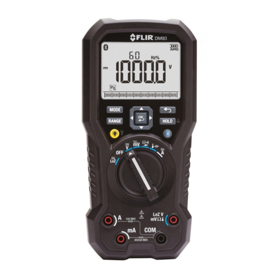
netzerotools.com 4 Description 4.1 Meter description Figure 4.1 Front view LCD display. Function buttons, see section 4.3 Function buttons, page 10. Selector pad. Function switch, see section 4.2 Function switch, page 9. Probe input terminals. #T559824; r. AH/ 9541/9541; en-US netzerotools.com... -
Page 15: Function Switch
netzerotools.com 4 Description Figure 4.2 Rear view Probe clips. Tilt stand. Work light. Battery compartment cover. 4.2 Function switch The meter can measure voltage through the probe inputs. A low- impedance load is placed across the inputs to stabilize the measurement. -
Page 16: Function Buttons
netzerotools.com 4 Description The meter can measure resistance, continuity, or diode polarity through the probe inputs. The type of measurement is selected by button. The meter can measure capacitance through the probe inputs or temperature through a thermocouple adapter. The type of meas- urement is selected by the button. -
Page 17: Display Description
netzerotools.com 4 Description • Press the button to enable/disable the display backlight. • Press and hold the button for 2 seconds to enable/disable the work light. Press the button to enable/disable METERLiNK® (Bluetooth) communication, see section 5.14 Streaming measurement data using Bluetooth, page 25. - Page 18 netzerotools.com 4 Description Indicates that the meter is displaying peak minimum values. Indicates that the meter is in Auto range mode. Indicates that the meter is in Hold mode. Indicates that the meter is in Locked mode. Indicates the active memory location (1–99). Indicates the battery voltage status.
- Page 19 netzerotools.com 4 Description 20,000 point Automatic Data Recording (Sampling) mode icon. Setup mode icon. Silent mode icon. 4.5.1 Probe indicator When the probe leads are not plugged into the correct jack sockets for the meas- urement selected by the function switch, PROBE is displayed. 4.5.2 Out-of-range warning If the input is over/under the full-scale range in Manual range mode, or if the sig- nal has exceeded the maximum/minimum input in Auto range mode, OL is...
-
Page 20: Operation
netzerotools.com 5 Operation Note Before operating the device, you must read, understand, and follow all in- structions, dangers, warnings, cautions, and notes. Note When the meter is not in use, the function switch should be set to the position. Note When connecting the probe leads to the device under test, connect the nega- tive lead before connecting the positive lead. -
Page 21: Auto/Manual Range Mode
netzerotools.com 5 Operation Auto select mode is the default mode of operation. When a new function is se- lected with the function switch, the starting mode is Auto select and the indi- cator is displayed. To enter Manual select mode, press the button. -
Page 22: Resistance Measurements
netzerotools.com 5 Operation Use the button to select AC, DC, or AC+DC voltage measurement. • indicator will be displayed for AC measurements. • indicator will be displayed for DC measurements. • indicator will be displayed for AC+DC measurements. Connect the probe leads in parallel to the part under test. Read the voltage value on the display. -
Page 23: Diode Test
netzerotools.com 5 Operation Use the button to select continuity measurement. The indicator will be displayed. Insert the black probe lead into the negative terminal and the red probe lead into the positive terminal. Touch the tips of the probe across the circuit or component under test. If the resistance is 30 ±... -
Page 24: Capacitance Measurements
netzerotools.com 5 Operation The diode or semiconductor junction can be evaluated as follows: • If one of the readings displays a value (typically 0.400 V or 0.900 V) and the other reading displays OL, the component is good. • If both readings display OL, the component is open. •... -
Page 25: Current Measurements
netzerotools.com 5 Operation To avoid electrical shock, disconnect the thermocouple adapter before turn- ing the function switch to another position. 5.10 Current measurements Current is measured by disconnecting the part under test and connecting the probe leads in series with the part, see Figure 5.1. Figure 5.1 Disconnected component Set the function switch to the position. - Page 26 netzerotools.com 5 Operation 5.11.1 Selecting the mode The mode icons applicable for the selected measurement type are displayed in the lower part of the display. When a mode is enabled, the icon is framed. Figure 5.2 Mode icons (AC voltage measurements): Peak mode and Silent mode are enabled Press the button to navigate to the desired mode icon.
- Page 27 netzerotools.com 5 Operation 5.11.4 Min/Max/Avg mode In Min/Max/Avg mode, the meter captures and displays the minimum or maxi- mum values and updates only when a higher/lower value is registered. The meter also averages the total sum of all recorded values. Use the selector pad to select and enable the Min/Max/Avg mode.
- Page 28 netzerotools.com 5 Operation Use the selector pad to select and enable dBm mode. Press the button to toggle between the display of dB and dBm. 5.11.8 Manual Data Recording mode The meter has 99 memory locations for the storage of measurement data. Use the selector pad to select and enable Manual Data Recording mode.
- Page 29 netzerotools.com 5 Operation Press the button to activate the displayed option: • VIEW: The secondary display shows the current memory location. The main display shows the data stored in the current memory location. Use button to change the memory location. Use the but- ton to change the memory location to the beginning or end.
-
Page 30: Normal Hold Mode And Auto Hold Mode
netzerotools.com 5 Operation Press the button to activate the displayed option: • APO: Press the button to change the auto power off time. • b.Lit: Press the button to change the auto backlight off time. • Cntin: Press the button to change the continuity threshold. •... -
Page 31: Locked Mode
5.14 Streaming measurement data using Bluetooth 5.14.1 General Some IR cameras from FLIR Systems support Bluetooth communication, and to those cameras you can stream measurement data from the meter. The data is then merged into the result table in the IR image. -
Page 32: Maintenance
As with most electronic products, this equipment must be disposed of in an envi- ronmentally friendly way, and in accordance with existing regulations for elec- tronic waste. Please contact your FLIR Systems representative for more details. #T559824; r. AH/ 9541/9541; en-US netzerotools.com... -
Page 33: Technical Specifications
netzerotools.com 7 Technical specifications 7.1 General specifications Maximum voltage applied to any terminal: 1000 V DC or 1000 V AC RMS. Display count: 4000/40 000. Polarity indication: Automatic, positive implied, negative indicated. Over-range indication: OL. Measuring rate: 10 samples per second. Power requirements: 6 ×1.5 V AAA alkaline batteries. -
Page 34: Electrical Specifications
netzerotools.com 7 Technical specifications Application field Circuits not connected to mains Circuits directly connected to a low- voltage installation Building installation. Source of the low-voltage installation EMC: EN 61326-1. Pollution degree: 2. Shock vibration: Per MIL-PRF-28800 for a Class 2 instrument. Drop protection: 1.5 m (5ʹ). - Page 35 netzerotools.com 7 Technical specifications Table 7.1 Voltage. Resolution of specifications in the 3 ¾-digit mode. Mode Range Accuracy 40.00 mV 0.05%+3d 400.0 mV 4.000 V 40.00 V 0.05%+1d 400.0 V 1000 V 40 Hz to 70 Hz to 1 kHz to 5 kHz to 70 Hz 1 kHz...
- Page 36 netzerotools.com 7 Technical specifications • V AC: CMRR > 60 dB at DC, 50 Hz/60 Hz. • V DC: CMRR > 100 dB at DC, 50 Hz/60 Hz. • NMRR > 50 dB at DC, 50 Hz/60 Hz. AC conversion type: AC coupled, true RMS responding, calibrated to the sine wave input.
- Page 37 netzerotools.com 7 Technical specifications Minimum resolution: 1 µA in the 40 mA range. Maximum measuring time: 1 minute at A input, 10 minutes at mA input. Rest time is 20 minutes minimum. AC conversion type: The AC conversion type is the same as for the voltage. Table 7.3 AC additional specifications Mode Range...
- Page 38 netzerotools.com 7 Technical specifications Table 7.5 Frequency counter sensitivity Function Range Sensitivity Sensitivity (peak to peak) (peak to peak) 5 Hz to 10 kHz 10–100 kHz 40.000 mV 10 mV 10 mV 400.00 mV 100 mV 100 mV 4.0000 V 40.000 V 10 V 10 V...
- Page 39 netzerotools.com 7 Technical specifications Table 7.7 Continuity check. Resolution of specifications in the 3 ¾-digit mode. Range Resolution Accuracy 400.0 Ω 100 mΩ ±(0.2% + 2 dgt) Input protection: 1000 V DC or 1000 V AC RMS. Maximum open circuit voltage: Approx. 2.5 V. Maximum short test current: Approx.
- Page 40 netzerotools.com 7 Technical specifications Input protection: 1000 V DC or 1000 V AC RMS. Table 7.10 Temperature Range Resolution Accuracy –328℉ to 2192℉ 0.1℉ 1.0% + 36d –200℃ to 1200℃ 0.1℃ 1.0% + 20d Input protection: 1000 V DC or 1000 V AC RMS. Note Accuracy specification assumes the ambient temperature is stable to ±1℃...
-
Page 41: Technical Support
netzerotools.com 8 Technical support #T559824; r. AH/ 9541/9541; en-US netzerotools.com... -
Page 42: Warranties
PRICE AND HAVE NO OTHER OBLIGATION OR LIABIL- “Product”) purchased either directly from FLIR Commer- ITY TO BUYER WHATSOEVER. cial Systems Inc and affiliates (FLIR) or from an author- ized FLIR distributor or reseller that Purchaser registers 5. WARRANTY EXCLUSIONS AND DISCLAIMERS. -
Page 43: Warranty
7. NON-WARRANTY RETURN. Purchaser may request including accessories which may have their own warranty. that FLIR evaluate and service or repair a Product not cov- 3. WARRANTY PERIODS. The applicable Limited War- ered under warranty, which FLIR may agree to do in its ranty Period measured from the Purchase data are: sole discretion. - Page 44 RANTY AGREEMENT BETWEEN PURCHASER AND 7. NON-WARRANTY RETURN. Purchaser may request FLIR AND SUPERSEDES ALL PRIOR WARRANTY NE- that FLIR evaluate and service or repair a Product not cov- GOTIATIONS, AGREEMENTS, PROMISES AND ered under warranty, which FLIR may agree to do in its UNDERSTANDINGS BETWEEN PURCHASER AND sole discretion.
- Page 45 netzerotools.com netzerotools.com...
- Page 46 netzerotools.com A note on the technical production of this publication This publication was produced using XML — the eXtensible Markup Language. For more information about XML, please visit http://www.w3.org/XML/ A note on the typeface used in this publication This publication was typeset using Linotype Helvetica™ World. Helvetica™ was designed by Max Miedinger (1910–1980) LOEF (List Of Effective Files) T501024.xml;...
- Page 47 netzerotools.com netzerotools.com...
- Page 48 netzerotools.com Publ. No.: T559824 Release: Commit: 9541 Head: 9541 Language: en-US Modified: 2013-10-31 Formatted: 2013-10-31 netzerotools.com...
Need help?
Do you have a question about the DM93 and is the answer not in the manual?
Questions and answers