Table of Contents
Advertisement
Quick Links
This user's guide describes the characteristics, operation, and use of the AFE3010 evaluation module
(EVM). This EVM is designed to evaluate the performance of the AFE3010 as a ground-fault circuit
interrupter IC with self-tests. Throughout this document, the terms evaluation board, evaluation module,
and EVM are synonymous with the AFE3010EVM. This document also includes a schematic, reference
printed-circuit board (PCB) layouts, and a complete bill of materials (BOM).
SLYU038 – June 2020
Submit Documentation Feedback
AFE3010 Evaluation Module
Copyright © 2020, Texas Instruments Incorporated
User's Guide
SLYU038 – June 2020
AFE3010 Evaluation Module
1
Advertisement
Table of Contents

Related Manuals for Texas Instruments AFE3010EVM


Summary of Contents for Texas Instruments AFE3010EVM
- Page 1 (EVM). This EVM is designed to evaluate the performance of the AFE3010 as a ground-fault circuit interrupter IC with self-tests. Throughout this document, the terms evaluation board, evaluation module, and EVM are synonymous with the AFE3010EVM. This document also includes a schematic, reference printed-circuit board (PCB) layouts, and a complete bill of materials (BOM).
-
Page 2: Table Of Contents
List of Figures ..Shunt (H9–H19) Connector Setup: Red Squares = Shunt Position, Green Circle = Open or no shunt ..................AFE3010EVM and Hardware Setup ..........Simplified AFE3010EVM Schematic and Hardware for Quick Setup ....................AFE3010EVM Schematic ....................AFE3010EVM Top Overlay ................... -
Page 3: Overview
Quantity AFE3010EVM test board AFE3010EVM Shunt, 100-mil, gold-plated, black SNT-100-BK-G Related Documentation From Texas Instruments This document provides information regarding Texas Instruments' integrated circuits used in the assembly of the AFE3010EVM. Table 2. Related Documentation Document Description Literature Number AFE3010... -
Page 4: Hardware
AC source. The entire board is high-voltage and thus no part of it is safe to touch when it is connected to a live source. The AFE3010EVM was not designed to actually break or interrupt the source voltage if a fault current is detected. -
Page 5: Operation
Operation Quick Start Setup Follow these procedures to set up and ensure proper operation of the AFE3010EVM with its onboard current transformer, T1. Step 1. Gather equipment for safe high-voltage test setup. Step 2. Ensure the EVM is completely de-energized and not connected to any source voltage. -
Page 6: Shunt (H9-H19) Connector Setup: Red Squares = Shunt Position, Green Circle = Open Or No Shunt
Operation www.ti.com Figure 1. Shunt (H9–H19) Connector Setup: Red Squares = Shunt Position, Green Circle = Open or no shunt AFE3010 Evaluation Module SLYU038 – June 2020 Submit Documentation Feedback Copyright © 2020, Texas Instruments Incorporated... -
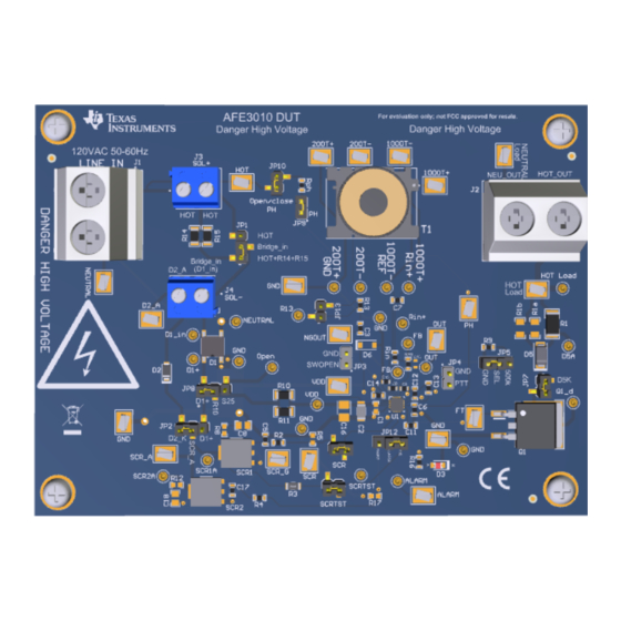
Page 7: Afe3010Evm And Hardware Setup
Operation www.ti.com 120 VAC 50-60 Hz RSOL = {10kO- 15kO} Safety Figure 2. AFE3010EVM and Hardware Setup SLYU038 – June 2020 AFE3010 Evaluation Module Submit Documentation Feedback Copyright © 2020, Texas Instruments Incorporated... -
Page 8: Simplified Afe3010Evm Schematic And Hardware For Quick Setup
3.1.1 Quick Start Setup - Testing the Trip Current Follow these procedures to test at what fault current the AFE3010EVM trips to interrupt the fault current. Note that the EVM was not mechanically constructed to break the circuit. Step 1. Power off the source voltage. -
Page 9: Measurements (Optional)
5. Connect the negative lead of the differential probe to any GND pin on the board. Note that the ground of the board is not Earth ground. The ground of the board is floating and a high-voltage node just as is every node on the AFE3010EVM that is never safe to have exposed. EVM Components This section summarizes the AFE3010EVM components. -
Page 10: D2, Scr1, Scr2
R1. R1a and R1b are not populated, but can be populated if user wants to test with lower power rated resistors in parallel. D5 prevents any current flowing in the opposite direction, which can occur under certain bias conditions of AFE3010 Evaluation Module SLYU038 – June 2020 Submit Documentation Feedback Copyright © 2020, Texas Instruments Incorporated... -
Page 11: Jp1-Jp13
4.19 TP1–TP25 These test points allow for the user to probe various pins and nodes on the EVM with secure hook connections. SLYU038 – June 2020 AFE3010 Evaluation Module Submit Documentation Feedback Copyright © 2020, Texas Instruments Incorporated... -
Page 12: Schematic, Pcb Layout, And Bill Of Materials
NOTE: Board layouts are not to scale. These figures are intended to show how the board is laid out; they are not intended to be used for manufacturing AFE3010EVM PCBs. Schematics Figure 4 shows the schematics for the AFE3010EVM PCB. AFE3010 Evaluation Module SLYU038 – June 2020 Submit Documentation Feedback... -
Page 13: Afe3010Evm Schematic
TP24 JP11 AFE3010AIRGT SCR_A 100pF TP10 ALARM TP23 ALARM SCRTST SCR2A SCRTST 1.1k SCR2 Alert 2.2nF 250V 1.50k JP12 470nF Figure 4. AFE3010EVM Schematic SLYU038 – June 2020 AFE3010 Evaluation Module Submit Documentation Feedback Copyright © 2020, Texas Instruments Incorporated... -
Page 14: Pcb Layout
Schematic, PCB Layout, and Bill of Materials www.ti.com PCB Layout Figure 5 through Figure 11 illustrate the PCB layout for the AFE3010EVM. Figure 5. AFE3010EVM Top Overlay Figure 6. AFE3010EVM Bottom Overlay Figure 7. AFE3010EVM Top Layer Figure 8. AFE3010EVM Bottom Layer AFE3010 Evaluation Module SLYU038 –... -
Page 15: Afe3010Evm Drill Drawing
Schematic, PCB Layout, and Bill of Materials www.ti.com Figure 9. AFE3010EVM Top Solder Figure 10. AFE3010EVM Bottom Solder Figure 11. AFE3010EVM Drill Drawing SLYU038 – June 2020 AFE3010 Evaluation Module Submit Documentation Feedback Copyright © 2020, Texas Instruments Incorporated... -
Page 16: Bill Of Materials
Schematic, PCB Layout, and Bill of Materials www.ti.com Bill of Materials Table 3 provides the parts list for the AFE3010EVM. Table 3. Bill of Materials Designator Value Description Package Reference Part Number Manufacturer 3.3uF CAP, CERM, 3.3 uF, 50 V, ±10%, X7R, 1206_190... - Page 17 RES, 1.50 k, 1%, 0.1 W, 0603 0603 RC0603FR-071K5L Yageo R8, R12 RES, 0, 5%, 0.1 W, AEC-Q200 Grade 0, 0603 0603 ERJ-3GEY0R00V Panasonic SLYU038 – June 2020 AFE3010 Evaluation Module Submit Documentation Feedback Copyright © 2020, Texas Instruments Incorporated...
- Page 18 STANDARD TERMS FOR EVALUATION MODULES Delivery: TI delivers TI evaluation boards, kits, or modules, including any accompanying demonstration software, components, and/or documentation which may be provided together or separately (collectively, an “EVM” or “EVMs”) to the User (“User”) in accordance with the terms set forth herein.
- Page 19 www.ti.com Regulatory Notices: 3.1 United States 3.1.1 Notice applicable to EVMs not FCC-Approved: FCC NOTICE: This kit is designed to allow product developers to evaluate electronic components, circuitry, or software associated with the kit to determine whether to incorporate such items in a finished product and software developers to write software applications for use with the end product.
- Page 20 www.ti.com Concernant les EVMs avec antennes détachables Conformément à la réglementation d'Industrie Canada, le présent émetteur radio peut fonctionner avec une antenne d'un type et d'un gain maximal (ou inférieur) approuvé pour l'émetteur par Industrie Canada. Dans le but de réduire les risques de brouillage radioélectrique à...
- Page 21 www.ti.com EVM Use Restrictions and Warnings: 4.1 EVMS ARE NOT FOR USE IN FUNCTIONAL SAFETY AND/OR SAFETY CRITICAL EVALUATIONS, INCLUDING BUT NOT LIMITED TO EVALUATIONS OF LIFE SUPPORT APPLICATIONS. 4.2 User must read and apply the user guide and other available documentation provided by TI regarding the EVM prior to handling or using the EVM, including without limitation any warning or restriction notices.
- Page 22 Notwithstanding the foregoing, any judgment may be enforced in any United States or foreign court, and TI may seek injunctive relief in any United States or foreign court. Mailing Address: Texas Instruments, Post Office Box 655303, Dallas, Texas 75265 Copyright © 2019, Texas Instruments Incorporated...
- Page 23 TI products. TI’s provision of these resources does not expand or otherwise alter TI’s applicable warranties or warranty disclaimers for TI products. Mailing Address: Texas Instruments, Post Office Box 655303, Dallas, Texas 75265 Copyright © 2020, Texas Instruments Incorporated...
Need help?
Do you have a question about the AFE3010EVM and is the answer not in the manual?
Questions and answers