Table of Contents
Advertisement
Quick Links
Advertisement
Table of Contents

Subscribe to Our Youtube Channel
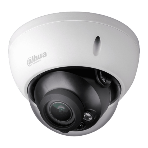
Summary of Contents for Dahua Technology HAC-HDBW2401RP-Z
- Page 1 HDCVI Camera User’s Manual Version 1.0.1...
-
Page 2: Table Of Contents
Table of Contents General Introduction ........................1 Overview ..........................1 Features..........................1 Device Framework .......................... 2 Device Cable Structure ........................4 Device Installation ........................... 7 Installation for Model A, B and D .................. 7 Installation for Model C ....................9 Menu .............................. - Page 3 Welcome Thank you for purchasing our HDCVI camera! This user’s manual is designed to be a reference tool for your system. Please read the following safeguard and warnings carefully before you use this series product! Please keep this user’s manual well for future reference! Important Safeguards and Warnings 1.Electrical safety ...
- Page 4 Please do not provide two or more power supply modes for the device, otherwise it may cause damage to the device. Statement Please refer to the actual product for more details; the manual is just for reference. The manual will be regularly upgraded according to the product update;...
-
Page 5: General Introduction
1 General Introduction 1.1 Overview This series HDCVI camera conforms to the HDCVI standard. It supports video signal high- speed long distance transmission without any delay. It can be controlled by the HCVR conforming to the HDCVI. 1.2 Features Adopt high performance CMOS image sensor, megapixel definition. -
Page 6: Device Framework
2 Device Framework Note: It fails to support OSD menu operation when it outputs SD video for model B and C; it realizes zoom and focus operation via UTC when it outputs SD video for model A and D. See Figure 2-1 for the dimension of model A. The unit is mm. Figure 2-1 See Figure 2-2 for the dimension of model B. - Page 7 Figure 2-3 See Figure 2-4 for the dimension of model D. The unit is mm. Figure 2-4...
-
Page 8: Device Cable Structure
3 Device Cable Structure Refer to Figure 3-1 for DC 12V power input port. Figure 3-1 Refer to Figure 3-2 for DC 12V/AC 24V power input port. Figure 3-2 Please refer to Figure 3-3 for power reverse port. Figure 3-3 Refer to Figure 3-4 for video output port. - Page 9 Video output port (gray): HDCVI video output port, support POC power supply, it can realize HD/SD switch output via OSD menu and UTC controller. Video output port (red): SDI video output port. Refer to Figure 3-5 for mobile video output port and cable sequence. Figure 3-5 Refer to Figure 3-6 for audio input port.
- Page 10 Alarm output common contact, on-off value alarm Orange ALARM_NC output. Alarm output normally open contact, on-off value Green ALARM_NO alarm output. Table 3-1...
-
Page 11: Device Installation
4 Device Installation Dome camera mainly uses ceiling installation; installation surface includes ceiling and wall. Attention: Please install the device in time after it is taken apart, which is to avoid the camera module being exposed to damp environment for too long. ... - Page 12 Step 1 Take out the installation position map from the accessories bag, and paste it on the ceiling or wall ① according to the cable outlet location, dig holes on the installation surface according to the installation position map, take out the expansion bolts ② from the accessories bag and insert them into the installation holes and fix them.
-
Page 13: Installation For Model C
Figure 4-3 Please refer to Table 4-1 for more details for five-direction description. Name Function It is to select OSD menu option in OSD menu. Short press to focus and long press to zoom when exiting OSD menu. Down Long press right button to zoom in, long press left button to zoom out. - Page 14 Figure 4-4 Step 1 Take out the installation position map from the accessories bag, and paste it on the ceiling or wall ① according to the cable outlet location, dig holes on the installation surface according to the installation position map, take out the expansion bolts ② from the accessories bag and insert them into the installation holes and fix them.
- Page 15 Figure 4-5 Step 6 Use fixing screws to fix the dome enclosure on the dome pedestal. So far, the device installation and cable connection have been completed, you can check the monitoring image via back-end encoding device.
-
Page 16: Menu
5 Menu 5.1 HCVR Settings This HDCVI camera series can adjust OSD menu via coaxial control. After connected the camera to the HDCVI series HCVR, from Main Menu->Setting->System->PTZ, you need to select the channel number for access and set control mode as HDCVI and the protocol as HD- CVI. - Page 17 Figure 5-3 See Table 5-1 for the details of button functions. Button Function Open menu 、 Select menu item Select menu value 、 Adjust lens zoom and auto trigger focus Note: Some of the buttons can only Adjust lens focus be applied for the motorized vari-focal camera.
-
Page 18: Appendix Ⅰ Maintenance
Appendix Ⅰ Maintenance Attention Please maintain the device according to the following instructions in order to ensure the image effect and long-term stable operation of the device. Maintenance for lens and mirror surface The lens and mirror surface are covered with antireflection coating, so it may produce hazardous substance and lead to performance reduction or scratch, dimness etc.


Need help?
Do you have a question about the HAC-HDBW2401RP-Z and is the answer not in the manual?
Questions and answers