Advertisement
Quick Links
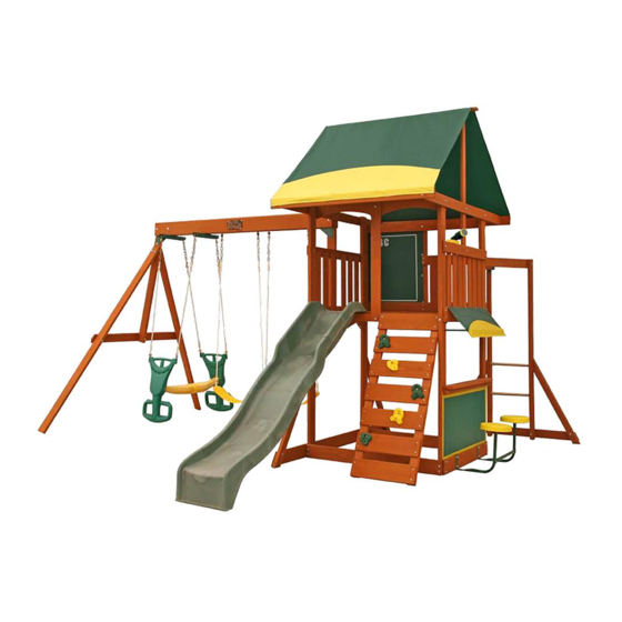
BROOKRIDGE PLAY SYSTEM - F23235
INSTALLATION AND OPERATING INSTRUCTIONS
Brookridge
Height: 9 feet
Length: 12 feet 11"
Width: 12 feet 9"
12'-9"
12'-11"
24'-11"
8-10 Hrs
Two person
assembly
3403235
3403235
WARNING
and give them to any future owner of this play system. Manufacturer contact information provided below.
OBSTACLE FREE SAFETY ZONE - 26' x 24'11" area requires Protective Surfacing. See page 3.
26'-0"
MAXIMUM VERTICAL FALL HEIGHT - 6'5"
CAPACITY - 9 Users Maximum, Ages 3 to 10; Weight Limit 110 lbs. (49.9 kg) per child.
RESIDENTIAL HOME USE ONLY. Not intended for public areas such as schools, churches, nurseries, day cares or parks.
Cedar Summit c/o ©Solowave Design Inc.
Mount Forest, ON Canada N0G 2L1
www.cedarsummitplay.com
support@cedarsummitplay.com
Customer Service
1-877-817-5682 (toll free)
To reduce the risk of serious injury or death, you must read and
follow these instructions. Keep and refer to these instructions often
Table of Contents
Warnings and Safe Play Instructions. . . . . . . . . . . . . . . pg. 2
Protective Surfacing Guidelines. . . . . . . . . . . . . . . . . . . pg. 3
Instructions for Proper Maintenance . . . . . . . . . . . . . . . pg. 4
About Our Wood - Limited Warranty . . . . . . . . . . . . . . pg. 5
Keys to Assembly Success . . . . . . . . . . . . . . . . . . . . . . pg. 6
Metric Conversion Sheets . . . . . . . . . . . . . . . . . . . . . pg. 7,8
Part ID . . . . . . . . . . . . . . . . . . . . . . . . . . . . . . . . . . . . . . . pg. 9
Installation of I.D./Warning Plaque . . . . . . . . . . . .Final Step
Rev 02/11/2015
Rev 02/04/2013
Advertisement

Related Manuals for Cedar Summit BROOKRIDGE PLAY SYSTEM


Summary of Contents for Cedar Summit BROOKRIDGE PLAY SYSTEM
-
Page 1: Table Of Contents
BROOKRIDGE PLAY SYSTEM – F23235 INSTALLATION AND OPERATING INSTRUCTIONS Brookridge Height: 9 feet Length: 12 feet 11" WARNING Width: 12 feet 9" To reduce the risk of serious injury or death, you must read and follow these instructions. Keep and refer to these instructions often and give them to any future owner of this play system. -
Page 2: Warnings And Safe Play Instructions
Warnings and Safe Play Instructions Warnings and Safe Play Instructions CONTINUOUS ADULT SUPERVISION REQUIRED. Most serious injuries and deaths on playground equipment have occurred CONTINUOUS ADULT SUPERVISION REQUIRED. Most serious injuries and deaths on playground equipment have occurred while children were unsupervised! Our products are designed to meet mandatory and voluntary safety standards. Complying while children were unsupervised! Our products are designed to meet mandatory and voluntary safety standards. -
Page 3: Protective Surfacing Guidelines
Protective Surfacing - Reducing Risk of Serious Head Injury From Falls. One of the most important things you can do to reduce the likelihood of serious head injuries is to install shock-absorbing protective surfacing under and around your play equipment. The protective surfacing should be applied to a depth that is suitable for the equipment height in accordance with ASTM F1292. -
Page 4: Instructions For Proper Maintenance
Instructions for Proper Maintenance Your Cedar Summit Play System is designed and constructed of quality materials with your child’s safety in mind. As with all outdoor products used by children, it will weather and wear. To maximize the enjoyment, safety and life of your Play Set, it is important that you, the owner, properly maintain it. -
Page 5: About Our Wood - Limited Warranty
About Our Wood Cedar Summit Premium Play Systems uses only premium playset lumber, ensuring the safest product for your children’s use. Although we take great care in selecting the best quality lumber available, wood is still a product of nature and susceptible to weathering which can change the appearance of your set. -
Page 6: Keys To Assembly Success
Keys to Assembly Success Tools Required • Tape Measure • #1, #2 & #3 Phillips • Open End Wrench • 3/16” Hex Key • Carpenters Level or Robertson Bits (7/16”, 1/2” & 9/16”) • 8’ Step Ladder • Carpenters Square or Screwdriver •... -
Page 7: Metric Conversion Sheets
support@cedarsummitplay.com... - Page 8 support@cedarsummitplay.com...
-
Page 9: Part Id
Part Identification (Reduced Part Size) Part Identification (Reduced Part Size) Part Identification (Reduced Part Size) Part Identification (Reduced Part Size) Actual Size Nominal Size 12pc. - 1503 - Wall Board 1/2 x 4 x 20" - 3631503- Box 2 " x 3¼" 7/16 ½... - Page 10 Part Identification (Reduced Part Size) Part Identification (Reduced Part Size) Nominal Size Actual Size 2pc. - 1779 - CE Access Board 1 x 6 x 17" - 3631779 - Box 2 1 x 6 " x 5⅜" ⅝ 5/4 x 3 1"...
- Page 11 Part Identification (Reduced Part Size) Part Identification (Reduced Part Size) Nominal Size Actual Size 1pc. - 1900 - Ridge 2 x 2 x 46 3/4" - 3641900 - Box 2 2 x 2 1½ x 1½ 2 x 3 1⅜" x 2½" 2 x 4 1⅜"...
- Page 12 1X 3320386 Rocks (5pk) (4pk) w. welded chain 3-Green 2-Yellow 1X 3320356 1X 3200184 1X 9320357 Big Backyard I.D Triangle Plate (4pk) Cedar Summit Plaque w hardware 1X 3533860 Green I.D Plaque 39" Glider Rope & Chain (4pk) w. welded chain 1X 3200184...
- Page 13 Hardware Identification (Actual Size) 1/4 x 1 1/2" 1/4 x 2 1/2" 4pc. - LS1 -Lag Screw - (9262212) 3pc. - LS2 -Lag Screw - (9272222) 1/4 x 3" 6pc. - LS3 -Lag Screw - (9262230) Hex Bolt 1/4 x 2" 24pc.
- Page 14 Hardware Identification (Actual Size) Hex Bolt 5/16 x 4 1/2" 5pc. - G5 - - (9277342) Hex Bolt 5/16 x 5 1/2" 4pc. - G7 - - (9277352) Hex Bolt 5/16 x 6" 2pc. - 2pc. 5/16" Glider Long Hex Bolt - (9277360) Bolt may not be exactly as it appears 21pc.
- Page 15 Step 1: Inventory Parts - Read This Before Starting Assembly STOP STOP STOP STOP T his is the time for you to inventory all your hardware, wood and accessories, referencing the parts identification sheets. This will assist you with your assembly. • T he wood pieces will have the four digit key number stamped on the ends of the boards. The wood pieces are referenced throughout the instructions with this number. • Please refer to Page 6 for proper hardware assembly. • E ach step indicates which bolts and/or screws you will need for assembly, as well as any flat washers, lock washers, t-nuts or lock nuts. I f there are any missing or damaged pieces or you need assistance with assembly please contact the Consumer Relations Department directly. Call us before going back to the store. 1-877-966-3738 support@cedarsummitplay.com R ead the assembly manual completely, paying special attention to ANSI warnings; C. notes; and safety/maintenance information on pages 1 - 6. B efore you discard your cartons fill out the form below. D. • T he carton I.D. stamp is located on the end of each carton. The tracking number is located on the Cedar Summit ID Plaque (3320356).
- Page 16 Step 2: Rock Wall Assembly Note: The holes in the rock boards must orient to the top of the boards. Fig. 2.1 1778 1778 1777 1777 1777 1779 0349 7-3/4” Note: Gaps between boards 2-1/4”, Approx not to exceed 2-3/8” A: Lay 2 (0349) Rock Rails down, side by side with angled edges facing down. (fig. 2.1) B: Place (1779) CE Access Board on the bottom of each (0349) Rock Rail as shown in fig. 2.1. Make sure (1779) CE Access Board is flush to the outside and bottom edges of each (0349). Attach using 4 (S2) #8 x 1-1/2” Wood...
- Page 17 Step 3: Swing Beam Assembly Warning: For your child’s safety, Fig. 3.4 orientate the swing hangers as shown to ensure your swing will have proper swing motion when installed. Failure to do so could result in premature failure of the swing hanger or swing chain.
- Page 18 Step 4: Swing End Assembly A: Attach 2 (1863) SW Posts to (1856) SW Upright using 2 (G4) 5/16 x 4” Hex Bolts (with lock washer, flat washer and t-nut). (fig. 4.1) Fig. 4.1 1863 5/16” 1856 T-Nut 5/16” T-Nut 5/16” Flat Washer 1862 5/16” Lock Washer 5/16” Flat Washer 5/16” Lock Washer 1863 B: Attach (1862) SW Support to both (1863) SW Posts and (1856) SW Upright using 3 (G5) 5/16 x 4-1/2” Hex Bolts (with lock washer, flat washer and t-nut). (fig. 4.1) Wood Parts Hardware 5/16 x 4” Hex Bolt SW Post 2 x 4 x 86-11/16” 1863 (5/16”...
- Page 19 Step 5: Attach Swing End to Swing Beam A: Place (4919) SW Rail Block in the centre between (1826) Front Beam and (1825) Back Beam and attach with 1 (H8) 1/4 x 4-1/4” Hex Bolt (with lock washer, flat washer and t-nut). (fig. 5.1 & 5.2) Fig. 5.1 Glider Hangers 1/4” Lock Fig. 5.2 Washer Warning: Glider Hangers must be 1/4” Flat tight and secure to Washer 4919 Swing Beams. 1826 1/4” T-Nut 1825 B: Attach Swing Beam Assembly to the side of the Swing End Assembly with the overhang (fig. 5.3 & 5.4) using 1 (G5) 5/16 x 4-1/2” Hex Bolt (with lock washer, flat washer and t-nut) in the top hole of Triangle Plate and 1 (G8) 5/16 x 2” Hex Bolt (with 2 flat washers and lock nut) in the bottom hole of Triangle Plate. (fig. 5.3) Make sure Swing End Assembly flares out at an angle. (fig. 5.4) C: Attach 2 Glider Hangers to the Swing Beam Assembly using 2 (G7) 5/16 x 5-1/2” Hex Bolt (with 2 flat washers & lock nut) per Glider Hanger. (fig. 5.1 & 5.3) 5/16” Lock...
- Page 20 Step 6: Monkey Rail Assembly Pre-drill all pilot holes using a 1/8” drill bit before installing wood screws. A: Insert 3 (1578) 1-1/8 x 15-7/8” Dowels into both (1943) MK Rail Long and (1565) MK Rail Short as shown in fig. 6.1. Note that (1943) MK Rail Long will connect to the (1931) Post when attaching to the fort and (1565) MK Rail Short will connect to (1936) MK Mount and the pilot holes on the (1943) MK Rail Long are on the bottom of the board. Note: Pilot holes 1” 1565 at top of board Shorter rail connects to 11” the MK Mount Fig. 6.1 1578 1578 1578 Longer rail 1943 connects to the Fort Post Note: Pilot holes at 15”...
- Page 21 Step 7: Monkey Ladder Assembly A: Insert 1 (1858) 1-1/8 x 18-5/8” Dowel into 2 (1367) Post MK as shown in fig. 7.1. Fig. 7.1 1858 1367 B: Make sure shoulder of dowel is against each post before pre-drilling pilot 1858 Fig. 7.2 holes. Drill 1/8” pilot holes through the posts and into the dowel to prevent splitting. (fig. 7.2) 1367 C: Attach (1858) 1-1/8 x 18-5/8” Dowel to both posts with 2 (S2) #8 x 1-1/2” Wood Screws per dowel. One screw is installed from top of the rails and the other from the bottom as shown in fig. 7.3. D: At bottom of (1367) Post MK attach (0353) MK Ground with 2 (H12) 1/4 x 3” Hex Bolts (with lock washer, flat washer and t-nut). Be sure to keep the bolts loose. (fig. 7.3) Note: Pre-drill all holes using a 1/8” drill bit before installing the lag screws. E: Make sure the assembly is square and then attach 1 (0369) Lower Diagonal to each end of (0353) MK Ground with 1 (H2) 1/4 x 2” Hex Bolt (with lock washer, flat washer and t-nut) per diagonal, keeping the bolts loose, and to each (1367) Post MK with 1 (LS2) 1/4 x 2-1/2” Lag Screw (with flat washer) per diagonal. Once lag screws are...
- Page 22 Step 8: Connect Monkey Bar Assemblies Note: Pre-drill all holes using a 1/8” drill bit before installing the pan screws. A: Using a MK Bracket connect both (1943) MK Rail Long and (1565) MK Rail Short to each (1367) Post MK with 1 (G10) 5/16 x 3” Hex Bolt (with lock washer, flat washer and t-nut) per bracket and MK Bracket to the rails using 2 (S6) #12 x 1” Pan Screws per rail as shown in fig. 8.1 and 8.2. B: Attach MK Bracket to both (1367) Post MKs with 2 (S6) #12 x 1” Pan Screws per bracket. (fig. 8.2) This end This end connects connects to MK Mount to Post 1943 90° 1565 MK Bracket Fig. 8.2 1-1/4” 5/16” T-Nut Fig. 8.1 5/16” Flat 1367 Washer...
- Page 23 Step 9: Cafe Wall Assembly Part 1 Note: Keep all bolts loose in this step. A: On the ground lay flat 2 (1931) Posts then attach (2036) Cafe Ground with 4 (H2) 1/4 x 2” Hex Bolts (with lock washer, flat washer and t-nut); (2032) End Floor using 2 (H2) 1/4 x 2” Hex Bolts (with lock washer, flat washer and t-nut) in the bottom holes; and (2030) Side Roof using 2 (H2) 1/4 x 2” Hex Bolts (with lock washer, flat washer and t-nut) as shown in fig. 9.1 and 9.2. Notice the hole locations in (2032) End Floor. Fig. 9.1 1931 2036 2030 2032 Notice the hole 1/4” Lock Washer locations of (2032) End Floor 1931 1/4” Flat...
- Page 24 Step 9: Cafe Wall Assembly Part 2 Note: Pre-drill all holes using a 1/8” drill bit before installing the lag screws. B: Place (2034) Wall Support on both (1931) Posts as shown in fig. 9.3. C: Place (2031) Roof Support across the bottom of (2032) End Floor, (2034) Wall Support and (2030) Side Roof then loosely attach using 3 (H2) 1/4 x 2” Hex Bolts (with lock washer, flat washer and t-nut) as shown in fig. 9.3 and 9.4. The (2031) Roof Support should sit 2-1/4” from the top of (2032) End Floor. (fig. 9.4) D: Make sure assembly is square and then fasten (2032) End Floor to (1931) Posts in the top holes using 2 (LS1) 1/4 x 1-1/2” Lag Screws (with flat washer). (fig. 9.3 and 9.5) E: Make sure (2034) Wall Support is square to the posts then attach to both (1931) Posts using 4 (S2) #8 x 1-1/2” Wood Screws. (fig. 9.3 and 9.5) F: Make sure the assembly is square then tighten all bolts from this step. 1/4” Lock 2031 Washer 1/4” Flat Washer Fig. 9.3 2030 1/4” 1931 T-Nut 2034 2032...
- Page 25 Step 10: Swing Wall Assembly Part 1 Note: Keep all bolts loose in this step. A: On the ground lay flat 2 (1931) Posts then attach (2029) Ground SW with 4 (H2) 1/4 x 2” Hex Bolts (with lock washer, flat washer and t-nut); (1895) Floor End using 2 (H2) 1/4 x 2” Hex Bolts (with lock washer, flat washer and t-nut) in the bottom holes; and (2030) Side Roof using 2 (H2) 1/4 x 2” Hex Bolts (with lock washer, flat washer and t-nut) as shown in fig. 10.1. B: Attach 1 (0369) Lower Diagonal to each side of the (2029) Ground SW with 1 (H2) 1/4 x 2” Hex Bolt (with lock washer, flat washer and t-nut) per diagonal. (fig. 10.1) 2030 Fig. 10.1 1931 0369 1895 2029 1/4” Lock 1931 Washer 1/4” Flat Washer Notice the hole locations of (1895) 0369 Floor End.
- Page 26 Step 10: Swing Wall Assembly Part 2 Note: Pre-drill all holes using a 1/8” drill bit before installing the lag screws. C: Place (2034) Wall Support on both (1931) Posts as shown in fig. 10.2. D: Place (2035) SW Mount across (1895) Floor End, (2034) Wall Support and (2030) Side Roof. Loosely attach using 3 (G4) 5/16 x 4” Hex Bolts (with lock washer, flat washer and t-nut) as shown in fig. 10.2. E: Make sure assembly is square and then fasten (1895) Floor End to (1931) Posts in the top holes using 2 (LS1) 1/4 x 1-1/2” Lag Screws (with flat washer); and (0369) Lower Diagonals to (1931) Posts with 1 (LS3) 1/4 x 3” Lag Screw (with flat washer) per diagonal. (fig. 10.2 and 10.3) F: Make sure (2034) Wall Support is square to the posts then attach to both (1931) Posts using 4 (S2) #8 x 1-1/2” Wood Screws. (fig. 10.3) G: Tighten all bolts, except for the (2035) SW Mount bolts, from this step. 5/16” Lock 2035 Washer Fig. 10.2 5/16” Flat Washer 2030 1931 2034 5/16”...
- Page 27 Step 11: Front Frame Assembly A: On the front side of the assembly, from the inside, attach (1908) Front Floor to each (1931) Post with 2 (H6) 1/4 x 4-3/4” Hex Bolts (with lock washer, flat washer and t-nut). (fig. 11.1 and 11.2) B: Flush to the bottom of (1908) Front Floor attach (1937) Centre Divider with 1 (H12) 1/4 x 3” Hex Bolt (with lock washer, flat washer and t-nut). (fig. 11.2) C: Attach (1937) Centre Divider to (2037) Front Top using 1 (H2) 1/4 x 2” Hex Bolt (with lock washer, flat washer and t-nut). (fig. 11.2) D: Make sure (2037) Front Top is square and level and then attach to both (1931) Posts using 4 (S7) #12 x 2” Pan Screws (with 3/16” flat washers). (fig. 11.2) Note: Pre-drill all holes using a 1/8” drill bit before installing the lag screws. E: Attach (1768) Lower Back to the bottom of (1931) Posts with 2 (LS3) 1/4 x 3” Lag Screws (with flat washer) in the top (pre-drilled) holes and 2 (S7) #12 x 2” Pan Screws (with 3/16” flat washers) in the bottom holes as shown in fig. 11.3. with 3/16” 1/4” Flat Fig. 11.2 Cafe Wall Fig. 11.1 Flat Washer Washer 1931 1-4”...
- Page 28 Step 12: Attach Gusset to Front Frame Assembly A: Make sure the assembly is square before proceeding. B: From the inside of the assembly, attach (0312) Gusset flush to the outside edge of (1931) Post on the Swing Wall using 2 (S4) #8 x 3” Wood Screws. The other end of the gusset should be tight against (1908) Front Floor. (fig. 12.1 and 12.2) C: Attach the other end of (0312) Gusset to (1908) Front Floor with 1 (S3) #8 x 2-1/2” Wood Screw and 1 (S4) #8 x 3” Wood Screw as shown in fig. 12.2. Fig. 12.1 Fig. 12.2 1931 1908 0312 0312 Flush to edge Wood Parts Hardware Gusset 2 x 3 x 16” #8 x 2-1/2” Wood Screw 0312 #8 x 3” Wood Screw support@cedarsummitplay.com...
- Page 29 Step 13: Back Wall Assembly Part 1 A: Attach (1894) Back Floor to (1761) Side Joist using 2 (H3) 1/4 x 2-1/2” Hex Bolts (with lock washer, flat washer and t-nut) and 2 (S7) #12 x 2” Pan Screws as shown in fig. 13.1. B: On the back side of the assembly, attach (1894) Back Floor to both (1931) Posts, with (1761) Side Joist on the inside of the assembly, using 2 (H5) 1/4 x 4-1/2” Hex Bolts (with lock washer, flat washer and t-nut). (fig. 13.2 and 13.3) C: Attach (2033) MK Mount to (1894) Back Floor with 1 (H13) 1/4 x 3-1/2” Hex Bolt (with lock washer, flat washer and t-nut). (fig. 13.2 and 13.3). 1-4” Fig. 13.1 Fig. 13.2 T-Nut Notice hole 1/4” Flat Washer positioned down 1761 1/4” Lock Washer 1894 2033 Back 1931 Notice hole towards top. 1-4” T-Nut 1/4” Flat Washer 1-4”...
- Page 30 Step 13: Back Wall Assembly Part 2 Note: Pre-drill all holes using a 1/8” drill bit before installing the lag screws. D: Attach (2033) MK Mount to (1906) Top Front Back using 1 (H12) 1/4 x 2” Hex Bolt (with lock washer, flat washer and t-nut). (fig. 13.4 and 13.6) E: Make sure (1906) Top Front Back is level and then attach to both (1931) Posts using 4 (S7) #12 x 2” Pan Screws (with 3/16” flat washers). (fig. 13.4) F: Attach (1768) Lower Back to the bottom of (1931) Posts with 2 (LS3) 1/4 x 3” Lag Screws (with flat washer) in the top (pre-drilled) holes and 2 (S7) #12 x 2” Pan Screws (with 3/16” flat washers) in the bottom holes as shown in fig.13.5 and 13.6. Fig. 13.6 Fig. 13.4 1/4” Flat 1/4” Lock Washer 1-4” Washer T-Nut 1906 with 3/16” Flat Washer 1931 Back...
- Page 31 Step 14: Attach Ground Stakes MOVE FORT TO FINAL LOCATION. FINAL LOCATION MUST BE LEVEL GROUND Warning! To prevent tipping and avoid potential injury, stakes must be driven 10-1/2” into ground. Digging or driving stakes can be dangerous if you do not check first for underground wiring, cables or gas lines. A: Drive 3 (0318) Ground Stakes 10-1/2” into the ground at 1 (1931) Post and 2 (0369) Lower Diagonals as shown in fig. 14.1. Attach using 2 (S3) #8 x 2-1/2” Wood Screws per ground stake. (fig. 14.2) Fig.
- Page 32 Step 15: Attach Rock Wall to Fort Note: Pre-drill all holes using a 1/8” drill bit before installing the wood screws. A: Place Rock Wall Assembly from Step 2 centred on and flush to top of (1908) Front Floor (fig. 15.1 and 15.3). Attach (0349) Rock Rails to (1908) Front Floor using 4 (S15) #8 x 1-3/4” Wood Screws as shown in fig. 15.2. B: Attach (1779) CE Access Board to top of Rock Wall Assembly, flush to top of (0349) Rock Rails using 4 (S2) #8 x 1-1/2” Wood Screws. (fig. 15.4) Fig. 15.1 Fig. 15.2 1937 1908 0349 Flush Front 1908 Fig. 15.3 0349 1779 0349 Fig.
- Page 33 Step 16: Floor Frame Assembly Part 1 A: Remove the middle and bottom bolts in (2035) SW Mount. Do not discard these bolts, you will re-install them after the (1903) Floor Joist has been attached. (fig. 16.2) B: From inside of the assembly, measure 2-3/4” down from the top of (1895) Floor End and (2032) End Floor (fig. 16.3 and 16.4), then attach (1903) Floor Joist to each board using the pilot holes with 2 (S4) #8 x 3” Wood Screws per end. Make sure there is a 5/8” gap between (2031) Roof Support and (1903) Floor Joist. (fig. 16.2 and 16.4) C: Reinstall the middle and bottom bolts in (2035) SW Mount and tighten all three bolts. (fig. 16.1) Fig. 16.1 (hidden behind board) 1905 2031 1761 Fig. 16.4 2032 Cafe Wall 5/8” Gap 1895 2032 1903 2-3/4” Swing Wall Side Swing Wall Side Fig. 16.2 2035 Fig. 16.3 1895 2034 1895 2-3/4”...
- Page 34 Step 16: Floor Frame Assembly Part 2 D: Install 1 (1890) CE Gap Board tight to each end of the assembly attaching to (1761) Side Joist, (1903) Floor Joist and (1908) Front Floor using 5 (S2) #8 x 1-1/2” Wood Screws per board. (fig. 16.5) Fig. 16.5 Swing Wall Side 1761 1903 1890 1890 1908 Wood Parts Hardware CE Gap Board 1 x 6 x 32-1/2” 10 x #8 x 1-1/2” Wood Screw 1890 support@cedarsummitplay.com...
- Page 35 Step 17: Attach Floor Boards A: In between both (1890) CE Gap Boards place 5 (1889) Floor Boards making sure all boards are evenly spaced. Attach to (1761) Side Joist, (1903) Floor Joist and (1908) Front Floor using 5 (S2) #8 x 1-1/2” Wood Screws per board. (fig. 17.1) Fig. 17.1 (hidden under floor boards) 1761 S2 x 5 per board (hidden behind boards) 1903 1890 1890 1889 1908 Wood Parts Hardware Floor Board 1 x 6 x 32-1/2” 25 x #8 x 1-1/2” Wood Screw 1889 support@cedarsummitplay.com...
- Page 36 Step 18: Chalk Wall Frame Assembly A: On the back of the assembly, tight to the bottom of (1906) Top Front Back, attach (1944) Panel Frame to (1931) Post using 2 (S2) #8 x 1-1/2” Wood Screws. (fig. 18.1 and 18.2) B: Place (1227) CE Wall Board tight to the top of (1894) Back Floor and flush to the edge of (1931) Post and (2033) MK Mount. Attach to post using 2 (S2) #8 x 1-1/2” Wood Screws. (fig. 18.2) 1931 Fig. 18.2 Fig. 18.1 1906 Front 2033 Back 1944 1894 1227 Note beveled edge faces inside Wood Parts Hardware Panel Frame 1 x 2 x 24-3/8” #8 x 1-1/2” Wood Screw 1944 CE Wall Board 1 x 4 x 20”...
- Page 37 Step 19: Attach Chalk Wall/Tarp to Fort A: Loosen the top bolt in (2033) MK Mount and place the Chalk Wall Tarp in between (2033) MK Mount and (1906) Top Front Back. (fig. 19.1 and 19.2) Fig. 19.1 B: Attach Chalk Wall Tarp to (1906) Top Front Back, (1944) Panel Frame, (1227) CE Wall Board and (2033) MK Mount using 12 (S5) #8 x 1/2” Pan Screws (with #8 flat washer) as shown in fig. 19.2 and 19.3. The 4 screws on (2033) MK Mount are attached from the inside of the assembly. (fig. 19.3) 1906 1931 Fig. 19.2 with #8 flat washers Back Loosen this bolt Fig. 19.3 Inside Fort View 2033 Fig. 19.3 Chalk Wall Tarp with #8 flat washers 1944 Evenly (hidden behind tarp) space all screws 1227 2033 with #8 flat washers Note: Leave these holes...
- Page 38 Step 20: Cafe Side Wall Assembly A: In between both (1931) Posts on Cafe Wall side evenly space and attach 3 (1503) Cedar Walls on each side of (2031) Roof Support to (2034) Wall Support and (2032) End Floor using 4 (S0) #8 x 7/8” Truss Screws per board. The gap between boards should be evenly spaced at 1”, not exceeding 1-1/4”. Make sure the bottom of the boards are tight against the floor boards and bevelled edges are facing out and are at the top of the boards. (fig. 20.1 and 20.2) 1931 Fig. 20.1 Cafe Wall Side Fig. 20.2 Note: Gaps between boards evenly spaced at 2031 1”, not to exceed 1-1/4” Bevelled edges towards top and facing out 1931 S0 x 24 1931 1503 2034 1503 Note: Some boards were removed for clarity...
- Page 39 Step 21: Swing Side Wall Assembly A: In between both (1931) Posts on Swing Wall side attach 6 (1503) Cedar Walls to (2034) Wall Support and (1895) Floor End using 4 (S0) #8 x 7/8” Truss Screws per board. The gap between boards should be evenly spaced at 1”, not exceeding 1-1/4”. Make sure the bottom of the boards are tight against the floor boards and bevelled edges are facing out and are at the top of the boards. (fig. 21.1 and 21.2) 2035 Note: Gaps between Fig. 21.2 boards evenly spaced at 1”, not to exceed 1-1/4” Bevelled edges towards top and 1931 facing out Note: Evenly space 3 on each side of SW Mount 1931 2034 x 4 per...
- Page 40 Step 22: Roof Frame Assembly A: Pre-drill pilot holes for the screws using a 1/8” drill bit and then attach one (1909) Tarp Front Back to each end of each (2030) Side Roof, making sure the pilot holes are centred on the end of (2030) Side Roof, with 4 (S2) #8 x 1-1/2” Wood Screws per (1909) Tarp Front Back. The tops of the Tarp Front Backs should be flush to the top of the Roof Sides. (fig. 22.1) B: At all 4 corners attach 1 Corner Brace using 3 (S5) #8 x 1/2” Pan Screw per brace as shown in fig. 22.2 and 22.3. C: Attach (1900) Ridge flush to the end of (2035) SW Mount with 2 (S4) #8 x 3” Wood Screws and to (2031) Roof Support with 1 (S4) #8 x 3” Wood Screw as shown in fig. 22.3. 2030 Fig. 22.1 1909 x 4 per board Corner Brace 1909 Fig. 22.2 2030 2030 1909 x 4 per board 1900 x 3 per brace Fig. 22.3 2031 2035 2030 1909 2030 1909 Wood Parts Hardware Other Parts...
- Page 41 Step 23: Attach Canopy to Roof Frame A: Place Canopy over (1900) Ridge making sure bottom edges of tarp are even on both sides of assembly. (fig. 23.1 and 23.2) B: Secure one side by attaching Canopy to 1 (1909) Tarp Front Back using 5 (S5) #8 x 1/2” Pan Screws (with #8 flat washer). (fig. 23.2) C: Make sure the Canopy is tight and smooth then secure opposite end of Canopy to (1909) Tarp Front Back using 5 (S5) #8 x 1/2” Pan Screws (with #8 flat washer). (fig. 23.2) D: Attach Canopy to each end of (1900) Ridge with 2 (S5) #8 x 1/2” Pan Screws (with #8 flat washer). (fig. 23.2) Fig. 23.2 Canopy 1900 Graphic Not Shown Fig. 23.1 x 5 per side with #8 flat washer 1909 Other Parts Hardware 1 x Canopy 12 x #8 x 1/2” Pan Screw (with #8 flat washer) support@cedarsummitplay.com...
- Page 42 Step 24: Connect Monkey Bar Assembly to Fort Pre-drill all pilot holes using a 1/8” drill bit before installing the lag screws. A: With a MK Bracket attach (1565) MK Rail Short to (2033) MK Mount with 1 (G10) 5/16 x 3” Hex Bolt (with lock washer, flat washer and t-nut) and 4 (S6) #12 x 1” Pan Screws, as shown in fig. 24.1 and 24.2. B: Measure 21-1/2” from top of (1943) MK Rail Long to top of (1890) CE Gap Board, then with a MB Mount Strap attach (1943) MK Rail Long to (1931) Post using 1 (LS2) 1/4 x 2-1/2” Lag Screw (with flat washer) in the centre hole and 2 (S6) #12 x 1” Pan Screws in the 2 end holes as shown in fig. 24.3. C: Tighten the top bolt in (2033) MK Mount. D: Make sure (1227) CE Wall Board, from Step 18 is tight to the floor boards, then attach to (2033) MK Mount using 2 (S2) #8 x 1-1/2” Wood Screws. (fig. 24.4 and 24.5) Fig. 24.4 MB Mount Strap Fig. 24.3 Fig. 24.5 2033 1943 1/4” Flat Washer 1227 Fig.
- Page 43 Step 25: Attach Monkey End Ground Stake A: Drive 1 (0318) Ground Stake 10-1/2” into the ground at one (1367) Post MK on the inside of the assembly and attach with 2 (S3) #8 x 2-1/2” Wood Screws. (fig. 25.1 & 25.2) Warning! To prevent tipping and avoid potential injury, stakes must be driven 10-1/2” into ground. Digging or driving stakes can be dangerous if you do not check first for underground wiring, cables or gas lines. Fig.
- Page 44 Step 26: Attach Slide to Fort Note: Pre-drill all holes using a 1/8” drill bit before installing the pan screws. A: Place Slide in the centre between (1937) Centre Divider and (1931) Post. (fig. 26.1 and 26.2) B: Attach slide to fort through the floor boards and into (1908) Front Floor using 3 (S7) #12 x 2” Pan Screws. (fig. 26.2 & 26.3) Fig. 26.3 Fig. 26.1 Slide Floor Boards Side View 1908 Fig. 26.2 1937 1931 1908 Centre Slide In Opening Slide Other Parts Hardware 1 x Slide #12 x 2”...
- Page 45 Step 27: Attach Cafe Canopy to Fort A: Feed Cafe Canopy Frame through the pocket of the Cafe Canopy. (fig. 27.1) B: With a helper, hold the Cafe Canopy Frame 3-1/4” down from bottom of (2032) End Floor, against both (1931) Posts on the Cafe Wall side of the assembly. (fig. 27.2 and 27.3) C: Attach Cafe Canopy Frame to both posts, tight to the bottom of (2032) End Floor, with 1 (S6) #12 x 1” Pan Screw per post. (fig. 27.3) D: Make sure the Cafe Canopy is smooth and tight then attach to the top of (2032) End Floor with 5 evenly spaced (S5) #8 x 1/2” Pan Screws (with #8 flat washer) as shown in fig. 27.4. On each side of the Cafe Canopy measure 1” down from the top of (2032) End Floor and 1/2” in from the edge of the canopy, then install 1 (S5) #8 x 1/2” Pan Screw (with #8 flat washer) to each side. (fig. 27.4) with #8 flat washer Fig. 27.1 Fig. 27.4 Cafe Canopy 1” Cafe Canopy Graphic Not Shown Cafe Frame 2032 Cafe Frame S5 with #8 flat Fig. 27.2 washer Fig. 27.3 2032 3-1/4” 1931 1931 Cafe Wall Side SIZE...
- Page 46 Step 28: Cafe Wall Assembly Part 1 A: Loosen the 4 bolts indicated on (2036) Cafe Ground, in fig. 28.2, then tuck the Brookridge Tarp between the (1931) Posts and (2036) Cafe Ground, down to the top of the bolts, 3/4” from top of board. (fig. 28.1 and 28.2) B: From outside the assembly, measure 1-1/2” up from the top of (2036) Cafe Ground, on both sides, and attach tarp to both (1931) Posts, 1/2” in from the edge of the tarp, with 2 (S5) #8 x 1/2” Pan Screws (with #8 flat washer). (fig. 28.2) C: Measure 1-1/2” down from the top of the tarp and attach to both (1931) Posts, 1/2” in from the edge of the tarp, with 2 (S5) #8 x 1/2” Pan Screws (with #8 flat washer). (fig. 28.2) D: Attach a third (S5) #8 x 1/2” Pan Screw (with #8 flat washer) to each side, 6-5/8” from the first two screws, as shown in fig. 28.2. Fig. 28.2 1931 Outside Fort View Fig. 28.1 Brookridge Tarp 1-1/2” 1931 6-5/8” 6-5/8” 1-1/2” with #8 flat washer 3/4” 2036 Loosen these bolts Hardware Other Parts #8 x 1/2” Pan Screw (#8 flat washer) 1 x Brookridge Tarp support@cedarsummitplay.com...
- Page 47 Step 28: Cafe Wall Assembly Part 2 E: On the outside of the assembly place 1 (1941) Water Sand Support overlapping Brookridge Tarp by 1” and flush to the outside edges of both (1931) Posts. Make sure the board is level then attach with 4 (S3) #8 x 2-1/2” Wood Screws. (fig. 28.3) F: Attach (2028) Cafe Top tight to the top of (1941) Water Sand Support with 3 (S7) #12 x 2” Pan Screws. Make sure the notched edges are tight to the posts, . (fig. 28.3) G: From the inside of the assembly and 1/2” in from the edge of the tarp, attach tarp to (2036) Cafe Ground and (1941) Water Sand Support with 4 evenly spaced (S5) #8 x 1/2” Pan Screws (with #8 flat washer) per board. The distance between screws should be 8”. (fig. 28.4) H: Tighen the previously loosened bolts. 1931 Fig. 28.3 Outside Fort View 1931 15” 2036 Fig. 28.4 Inside Fort View 1941 2028 8” 8” 1941 8” 2036 Wood Parts Hardware #8 x 2-1/2” Wood Screw Cafe Top 5/4 x 4 x 35-7/8”...
- Page 48 Step 29: Stool Seat Assembly A: Using the hardware provided with the Stool Seat Assembly attach 1 Seat to 1 Seat Support and then create a second seat as in fig. 29.1. B: Keeping the Cross Brace tight to the Seat Assemblies, fasten the Cross Brace to each of the Seat Assemblies using the hardware provided. (fig. 29.2) 1/4-20 x 1” Machine Screw Fig. 29.1 1/4” Lock washer 1/4” Flat washer Seat Spacer Seat Support 1/4-20 Lock Nut Cross Brace Fig. 29.2 1/4-20 x 1-1/4” Machine Screw Hardware Other Parts 2 x 1/4” Lock Washer 1 x Stool Set (with hardware) support@cedarsummitplay.com...
- Page 49 Step 30: Attach Stool Seat to Fort A: Attach the Stool Seat Assembly to (2036) Cafe Ground using 2 (G2) 5/16 x 1” Hex Bolt (with lock washer, flat washer and t-nut) per Seat Assembly. (fig. 30.1 and 30.2) Fig. 30.1 2036 Parts Removed for Clarity 5/16” Flat Washer 5/16” Lock 5/16” Washer T-Nut 2036 Fig. 30.2 Hardware 5/16 x 1” Hex Bolt (5/16” lock washer, 5/16” flat washer, 5/16” t-nut) support@cedarsummitplay.com...
- Page 50 Step 31: Attach Swing Assembly to Fort A: Attach Swing Assembly from Step 5 to (2035) SW Mount with 1 (G5) 5/16 x 4-1/2” Hex Bolt (with lock washer, flat washer and t-nut) and 1 (G8) 5/16 x 2” Hex Bolt (with 2 flat washers and 1 lock nut) as shown in fig. 31.1. Fig. 31.1 5/16” 2035 T-Nut 5/16” Lock Washer 5/16” Flat Washer 5/16” Lock Nut 5/16” Flat Washer 5/16” Flat Washer Hardware 5/16 x 2” Hex Bolt (5/16” flat washer x 2, 5/16” lock nut) 5/16 x 4-1/2” Hex Bolt (5/16”...
- Page 51 Step 32: Attach Swing Ground Stakes A: Drive one (0318) Ground Stake 10-1/2” into the ground at each (1863) SW Post on the inside of the assembly and attach with 2 (S3) #8 x 2-1/2” Wood Screws per ground stake. (fig. 32.1 and 32.2) Warning! To prevent tipping and avoid potential injury, stakes must be driven 10-1/2” into ground. Digging or driving stakes can be dangerous if you do not check first for underground wiring, cables or gas lines. Fig.
- Page 52 Step 33: Glider Assembly A: Attach 1 Glider End to the Glider Seat using 1 5/16” Glider Long Hex Bolt (with 2 flat washers and 1 lock nut). Repeat for the second Glider End. (fig. 33.1) B: Install 2 Glider Rope with Chains into each Glider End using 2 - 5/16” Flat Washers and 1 Lock Nut per rope. (fig. 33.1) Glider may not be as shown. Appearance may vary. Fig. 61.1 Glider Rope and Chain 5/16 Flat Washer-Zinc 5/16 Flat Washer-Zinc 5/16 Lock 5/16 Lock Nut 5/16 x Glider Long Hex Bolt 5/16 Flat Washers 5/16 Lock...
- Page 53 Step 34: Attach Accessories to Fort If Bolt protrudes Warning! Check entire play centre for beyond T-Nut bolts protruding beyond T-Nuts. Use extra washers to eliminate this condition. Use an extra Flat W asher A: Connect the assembled Glider Swing to the Glider Hangers previously installed. (fig. 34.1) B: Attach 2 Belt Swings to the Bolt-Thru Swing Hangers. (fig. 34.1) C: Attach 1 Telescope to (1931) Post on the Monkey Ladder side with 2 (S2) #8 x 1-1/2” Wood Screws as shown in fig. 34.1 and 34.2 and 34.3. Fig.
- Page 54 Final Step: Attach I.D. Plaque ATTACH THIS WARNING & I.D. PLAQUE TO A PROMINENT LOCATION ON YOUR PLAY EQUIPMENT! (Fort or Swing Post) This provides warnings concerning safety and important contact information. A Tracking Number is provided to allow you to get critical information or order replacement parts for this specific model Attach with (S5) #8 x 1/2"...
- Page 55 NOTES NOTES support@cedarsummitplay.com...
- Page 56 MAIL TO: Fill out your registration card online at Solowave Design www.cedarsummitplay.com/registration 375 Sligo Road W. Mount Forest, Ontario, Canada Cedar Summit would like to say Thank You for N0G 2L0 your time and feedback. Attention: Customer Service REVISION: 11/28/12...
Need help?
Do you have a question about the BROOKRIDGE PLAY SYSTEM and is the answer not in the manual?
Questions and answers