Advertisement
Quick Links
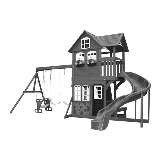
SUMMERSTONE PLAY SYSTEM - F23135
INSTALLATION AND OPERATING INSTRUCTIONS
10'-9"
18'-1"
30'-1"
10-14 Hrs
TWO PERSON
ASSEMBLY
3403135
WARNING
and give them to any future owner of this play system. Manufacturer contact information provided below.
OBSTACLE FREE SAFETY ZONE - 30'1" x 26' area requires Protective Surfacing. See page 3.
26'
MAXIMUM VERTICAL FALL HEIGHT - 6'5"
CAPACITY - 10 Users Maximum, Ages 3 to 10; Weight Limit 110 lbs. (49.9 kg) per child.
RESIDENTIAL HOME USE ONLY. Not intended for public areas such as schools, churches, nurseries, day cares or parks.
Cedar Summit
c/o ©Solowave Design L.P.
Mount Forest, ON Canada
N0G 2L0
www.cedarsummitplay.com
support@cedarsummitplay.com
Customer Service
1-877-817-5682 (toll free)
1-519-323-2258
To reduce the risk of serious injury or death, you must read and
follow these instructions. Keep and refer to these instructions often
Table of Contents
Warnings and Safe Play Instructions . . . . . . . . . . pg. 2
Protective Surfacing Guidelines . . . . . . . . . . . . . . pg. 3
Instructions for Proper Maintenance . . . . . . . . . pg. 4
About Our Wood - Limited Warranty . . . . . . . . . pg. 5
Keys to Assembly Success . . . . . . . . . . . . . . . . . . . pg. 6
Metric Conversion Sheets . . . . . . . . . . . . . . . . . .pg. 7,8
Part ID . . . . . . . . . . . . . . . . . . . . . . . . . . . . . . . . . . . . pg. 9
Installation of I.D./Warning Plaque . . . . . . . Final Step
Rev 12/03/2014
Advertisement

Related Manuals for Cedar Summit F23135


Summary of Contents for Cedar Summit F23135
-
Page 1: Table Of Contents
SUMMERSTONE PLAY SYSTEM – F23135 INSTALLATION AND OPERATING INSTRUCTIONS WARNING To reduce the risk of serious injury or death, you must read and follow these instructions. Keep and refer to these instructions often and give them to any future owner of this play system. Manufacturer contact information provided below. -
Page 2: Warnings And Safe Play Instructions
Warnings and Safe Play Instructions CONTINUOUS ADULT SUPERVISION REQUIRED. Most serious injuries and deaths on playground equipment have occurred while children were unsupervised! Our products are designed to meet mandatory and voluntary safety standards. Complying with all warnings and recommendations in these instructions will reduce the risk of serious or fatal injury to children using this play system. -
Page 3: Protective Surfacing Guidelines
Protective Surfacing - Reducing Risk of Serious Head Injury From Falls One of the most important things you can do to reduce the likelihood of serious head injuries is to install shock-absorbing protective surfacing under and around your play equipment. The protective surfacing should be applied to a depth that is suitable for the equipment height in accordance with ASTM F1292. -
Page 4: Instructions For Proper Maintenance
Instructions for Proper Maintenance Your Cedar Summit Play System is designed and constructed of quality materials with your child’s safety in mind. As with all outdoor products used by children, it will weather and wear. To maximize the enjoyment, safety and life of your Play Set, it is important that you, the owner, properly maintain it. -
Page 5: About Our Wood - Limited Warranty
About Our Wood Cedar Summit Premium Play Systems uses only premium playset lumber, ensuring the safest product for your children’s use. Although we take great care in selecting the best quality lumber available, wood is still a product of nature and susceptible to weathering which can change the appearance of your set. -
Page 6: Keys To Assembly Success
Keys to Assembly Success Tools Required • Tape Measure • #1, #3 Phillips or Robertson • Open End Wrench • 3/16” Hex Key • Carpenters Level bit or Screwdriver (1/2” & 7/16”) • 8’ Step Ladder • Carpenters Square • Ratchet(1/2” & 7/16” •... -
Page 7: Metric Conversion Sheets
support@cedarsummitplay.com... - Page 8 support@cedarsummitplay.com...
-
Page 9: Part Id
Part Identification (Reduced Part Size) Part Identification (Reduced Part Size) Part Identification (Reduced Part Size) Part Identification (Reduced Part Size) Actual Size Nominal Size 4pc. 2234 Mid Siding 3/8 x 3 1/2 x 5⅜" - 3632234 - Box 2 " x 3½" x 3½... - Page 10 Part Identification (Reduced Part Size) Part Identification (Reduced Part Size) Nominal Size Actual Size 2pc. 2237 - Back Wall 1 x 4 x 44⅞" - 3632237 - Box 2 1 x 5 " x 4½" ⅝ 1 x 6 " x 5⅜" ⅝...
- Page 11 Part Identification (Reduced Part Size) Part Identification (Reduced Part Size) Nominal Size Actual Size 5pc. - 2330 Rock Board A 1 x 6 x 23½" - 3632330 - Box 2 1 x 6 " x 5⅜" ⅝ 5/4 x 2 1"...
- Page 12 Part Identification (Reduced Part Size) Nominal Size Actual Size 2pc. - 2105 Bench Post 5/4 x 4 x 14" - 3632105 - Box 4 5/4 x 4 1 x 3½ 5/4 x 5 1 x 4½ 5/4 x 6 1 x 5½" 1pc.
- Page 13 Part Identification (Reduced Part Size) Nominal Size Actual Size 1pc. 2192 Cafe Top 5/4 x 6 x 38½" - 3632192 - Box 4 5/4 x 6 1 x 5½ 2 x 2 1½ x 1½ 2 x 3 1⅜" x 2½" 1pc.
- Page 14 Part Identification (Reduced Part Size) Nominal Size Actual Size 2pc. - 2164 - Floor Support 2 x 4 x 69½" - 3632164 - Box 3 2" x 6" 1⅜" x 5⅜" 2" x 4" 1⅜" x 3⅜" 2pc. - 2182 - Mid Post 2 x 4 x 86"...
- Page 15 Hardware Identification (Actual Size) 1/4 x 1 1/2" 1/4 x 2 1/2" 7pc. - LS1 -Lag Screw - (9262212) 2pc. - LS2 -Lag Screw - (9272222) 1/4 x 3" 6pc. - LS3 -Lag Screw - (9262230) Hex Bolt 1/4 x 2¼" 2pc.
- Page 16 Hardware Identification (Actual Size) 1/4 x 1 1/4 10pc. - PB2 -Pan Bolt - (9274211) Hex Bolt 5/16 x 4 1/2" 7pc. - G5 - - (9277342) Hex Bolt 5/16 x 5 1/2" 4pc. - G7 - - (9277352) 5/16” Glider Long Hex Bolt Hex Bolt 5/16 x 6"...
- Page 17 • Please retain this information for future reference. You will need this information if you contact the Consumer Relations Department. MODEL NUMBER: F23135 CARTON I.D. STAMP: __ __ __ __ __ 14459 ___ (Box 1) CARTON I.D. STAMP: __ __ __ __ __ 14459 ___ (Box 4) CARTON I.D.
- Page 18 Step 2: Access Ladder / Rockwall Assembly Part 1 A: Place (2250) Left Rail on left hand side of 4 (2254) Ladder Treads and (2251) Right Rail on right hand side with the grooves facing in. (fig. 2.1) B: Fit each (2254) Ladder Tread into grooves on both (2250) and (2251) Rails, make sure the top edge of the treads are flush to the front of the rails.
- Page 19 Step 2: Access Ladder / Rockwall Assembly Part 2 E: Place (2248) Ladder Gap on each rail so there is a 2-3/8” gap between (2248) Ladder Gap and the top (2254) Ladder Tread. Attach using 4 (S3) #8 x 2-1/2” Wood Screws. (fig. 2.4 and 2.5) F: Place (2252) Rock Rail on the ground next to (2251) Right Rail so it matches the orientation of the two rails as shown in fig.
- Page 20 Step 2: Access Ladder / Rockwall Assembly Part 3 H: Place (0705) Cedar Wall at top of the assembly and (1880) CE Wall Board at the bottom of the assembly as shown in fig. 2.7. Then place (2330) Rock Board A and (2257) Rock Board B as shown in fig. 2.7. Do not screw boards down yet.
- Page 21 Step 2: Access Ladder / Rockwall Assembly Part 4 K: Alternating colours and shapes, attach 1 rock to each rock board using 1 (PB2) 1/4 x 1-1/4” Pan Bolt (with lock washer, flat washer and barrel nut) and 1 (S10) #8 x 1” Pan Screw per rock. (fig. 2.9 and 2.10) The Pan Screw is placed in the hole beneath the Pan Bolt.
- Page 22 Step 3: Swing Beam Assembly WARNING: Fig. 3.4 For your child’s safety, orientate the swing hangers as shown to ensure your swing will have proper swing motion when installed. Failure to do so could result in premature failure of the swing hanger or swing chain.
- Page 23 Step 4: Swing End Assembly A: Attach 2 (1863) SW Posts to (1856) SW Upright using 2 (G4) 5/16 x 4” Hex Bolts (with lock washer, flat washer and t-nut). (fig. 4.1) Fig. 4.1 5/16” T-Nut 1863 1862 1856 5/16” T-Nut 5/16”...
- Page 24 Step 5: Attach Swing End to Swing Beam A: Place (4919) SW Rail Block in the centre between (1826) Front Beam and (1825) Back Beam and attach with 1 (H8) 1/4 x 4-1/4” Hex Bolt (with lock washer, flat washer and t-nut). (fig. 5.1 & 5.2) B: Attach Big Backyard Plaque over 1/4”...
- Page 25 Step 6: Door Assembly Part 1 A: On the inside of (8197) Door Panel, measure 17-3/4” up from the bottom and attach Catch Plate using 2 (S18) #6 x 1” Wood Screws. (fig. 6.1 and 6.2) B: On the inside of (8197) Door Panel above the Catch Plate attach 1 Door Handle using 2 (S13) #6 x 5/8” Pan Screws.
- Page 26 Step 6: Door Assembly Part 2 C: On the outside of the (8197) Door Panel attach the second Door Handle at approximately the same place as the one on the inside. Use 2 (S13) #6 x 5/8” Pan Screws. (fig. 6.3 and 6.4) D: In the window opening of (8197) Door Panel insert 1 Small Window from the outside and attach with 8 (S13) #6 x 5/8”...
- Page 27 Step 7: Bench Assembly A: Flush to the top of 1 (2105) Bench Post place 1 (2138) Seat Side, angled corners should face down and centred on the posts. Attach with 2 (S15) #8 x 1-3/4” Wood Screws. (fig. 7.1 and 7.2) B: Repeat Step A to create a second Post Assembly.
- Page 28 Step 8: Front Wall Assembly Part 1 A: Loosely attach 1 (2180) Post, (2179) Door Post and 1 (2182) Mid Post to (2178) Ground Front with 2 (H2) 1/4 x 2” Hex Bolts (with lock washer, flat washer and t-nut) in each board. Ensure that you maintain a 27-5/8” spacing between the two boards, as shown inf fig.8.1.
- Page 29 Step 8: Front Wall Assembly Part 2 C: With bevelled ends facing up loosely attach 2 (2181) Short Posts to (2164) Floor Support with 1 (H11) 1/4 x 2-3/4” Hex Bolt (with lock washer, flat washer and t-nut) per board. Hex bolts to be installed from the inside of the assembly.
- Page 30 Step 9: Back Wall Assembly Part 1 A: Loosely attach 1 (2180) Post and 1 (2182) Mid Post to (2177) Ground Back with 2 (H2) 1/4 x 2” Hex Bolts (with lock washer, flat washer and t-nut) per board. Make sure the bevelled ends of (2180) Post and (2182) Mid Post are facing up.
- Page 31 Step 9: Back Wall Assembly Part 2 D: Loosely attach (2186) Back Front Wall to each (2181) Short Post, to (2182) Mid Post and to (2180) Post with 4 (H2) 1/4 x 2” Hex Bolt (with lock washer, flat washer and t-nut). (fig. 9.3) E: Loosely attach (2185) Lower Back to each (2181) Short Post and to (2182) Mid Post with 3 (H3) 1/4 x 2-1/2”...
- Page 32 Step 10: Swing Wall Assembly Part 1 A: With at least one adult helper hold up the Front and Back Walls and loosely attach (2184) SW Ground using 4 (H4) 1/4 x 4” Hex Bolts (with lock washer, flat washer and t-nut) and (2188) SW End using 2 (H5) 1/4 x 4-1/2” Hex Bolts (with lock washer, flat washer and t-nut), in the top holes, to both (2180) Posts.
- Page 33 Step 10: Swing Wall Assembly Part 2 C: Above (2188) SW End loosely attach (2196) SW Top to both (2180) Posts using 4 (H5) 1/4 x 4-1/2” Hex Bolts (with lock washer, flat washer and t-nut). (fig. 10.3 and 10.4) D: Loosely attach (2194) SW Mount to (2188) SW End and (2196) SW Top with 2 (G5) 5/16 x 4-1/2”...
- Page 34 Step 11: Slide Wall Assembly A: Loosely attach (2189) SL Ground to the outside of each (2182) Mid Post with 4 (H4) 1/4 x 4” Hex Bolts (with lock washer, flat washer and t-nut). (fig. 11.1 and 11.2) B: With the bolt holes towards the bottom of the board loosely attach (2187) SL End to each outside (2181) Short Post with 2 (H6) 1/4 x 4-3/4”...
- Page 35 Step 12: Square and Secure Assembly A: Make sure assembly is square then tighten all bolts from Steps 10 and 11. (fig. 12.1) Note: Pre-drill all holes using a 3/16” drill bit before installing the lag screws. B: Fasten (2188) SW End to (2180) Posts, in the bottom holes, using 2 (LS3) 1/4 x 3” Lag Screws (with flat washer).
- Page 36 Step 13: Attach Swing Wall Gussets Note: Pre-drill all holes using a 3/16” drill bit before installing the lag screws. A: Tight to the bottom of (2188) SW End and top bevelled edge flush to outside edge of (2180) Posts, attach 1 (2113) Gussett II to each side using 2 (LS3) 1/4 x 3”...
- Page 37 Step 14: Attach SL Arch to Slide Wall A: Tight to the bottom of each (2164) Floor Support and flush to the outside edges of (2182) Mid Posts attach (2253) SL Arch with 4 (S2) #8 x 1-1/2” Wood Screws. (fig. 14.1 and 14.2) B: Attach (2187) SL End to (2181) Short Posts with 2 (S3) #8 x 2-1/2”...
- Page 38 Step 15: Attach Slide Wall Gussets A: Tight and flush to the outside edge of (2182) Mid Post and tight to the bottom of (2181) Short Post attach 1 (2239) Gusset to (2182) Mid Post and (2164) Floor Support on each side of the assembly with 2 (S3) #8 x 2-1/2” Wood Screws per gusset.
- Page 39 Step 16: Attach Ground Stakes MOVE FORT TO FINAL LOCATION. FINAL LOCATION MUST BE LEVEL GROUND WARNING: To prevent tipping and avoid potential injury, stakes must be driven 10-1/2” into ground. Digging or driving stakes can be dangerous if you do not check first for underground wiring, cables or gas lines. A: Drive 1 (0318) Ground Stakes 10-1/2” into the ground at both (0369) Lower Diagonals and 2 on the Slide Wall Side tight to (2182) Mid Post and (2189) SL Ground as shown in fig.
- Page 40 Step 17: Floor Assembly Part 1 A: Flush to the bottom of both (2187) SL End and (2188) SW End attach (2165) Joist with 2 (S4) #8 x 3” Wood Screws per end (fig. 17.1 and 17.2) Fig. 17.1 Swing Wall 2188 2187 2165...
- Page 41 Step 17: Floor Assembly Part 2 B: Tight to (2188) SW End and between both (2180) Posts attach 1 (2197) Floor Board to each (2164) Floor Support and to (2165) Joist with 5 (S2) #8 x 1-1/2” Wood Screws. (fig. 17.3 and 17.4) C: Measure 42”...
- Page 42 Step 17: Floor Assembly Part 3 E: Starting on the Swing Wall place (2198) Floor Board II tight to (2197) Floor Board and flush to the outside of the Back Wall (2164) Floor Support. (fig. 17.5 and 17.6) F: Evenly space 7 (2163) Floor Boards between (2198) Floor Board II and the middle (2197) Floor Board, flush to the outside of the Back Wall (2164) Floor Support.
- Page 43 Step 17: Floor Assembly Part 4 H: Next to middle (2197) Floor Board place 2 (2231) Gap Boards flush to the outside of the Back Wall (2164) Floor Support so the notched out corners surround each (2182) Mid Post. (fig. 17.7) I: Next to (2231) Gap Board place (2230) Floor Board III flush to the outside of the Back Wall (2164) Floor Support, then place a third (2231) Gap Board so the notched out corners fit against both outside (2181) Short Posts.
- Page 44 Step 18: Door Wall Assembly Part 1 A: Measure the distance between (2179) Door Post and Fig. 18.1 (2182) Mid Post to make sure it is 17-1/2”. If it does not meet this measurement loosen all bolts in (2179) Door Post and (2182) Mid Post, move posts until you achieve this measurement then re-tighten the bolts.
- Page 45 Step 18: Door Wall Assembly Part 2 C: Tight to the bottom of (2186) Back Front Wall and flush to the outside edges of (2180) Post and (2182) Mid Post attach (2166) Door Arch to (2180) Post, (2179) Door Post and (2182) Mid Post with 6 (S2) #8 x 1-1/2” Wood Screws.
- Page 46 Step 18: Door Wall Assembly Part 3 E: Align the notched out section of (2331) Door Stop with the Catch Plate on (8197) Door Panel then attach (2331) Door Stop to (2179) Door Post with 4 (S2) #8 x 1-1/2” Wood Screws so (2331) Door Stop overhangs the post by 1”.
- Page 47 Step 18: Door Wall Assembly Part 4 G: Loosely attach 2 (2168) Window Sides and 1 (2167) Window Divider to (2169) Window Bottom with 1 (H2) 1/4 x 2” Hex Bolt (with lock washer, flat washer and t-nut) per board as shown in fig. 18.8. Fig.
- Page 48 Step 18: Door Wall Assembly Part 5 H: Attach both (2168) Window Sides and (2167) Window Divider to the inside of (2166) Door Arch with 1 (H1) 1/4 x 1-1/2” Hex Bolt (with lock washer, flat washer and t-nut) per board as shown in fig. 18.9. (2169) Window Bottom is on the outside of (2180) Post and (2179) Door Post.
- Page 49 Step 18: Door Wall Assembly Part 6 L: Bend the short sides of the Faux Stone Panel flanges (measuring 20”) to a 90 angle to ensure a good fit. (fig 18.12 and 18.13) M: From the inside of the assembly, place Faux Stone Panel in opening between (2180) Post and (2179) Door Post, and tight against (2178) Ground Front and (2169) Window Bottom.
- Page 50 Step 19: Large Roof Support Assembly Part 1 A: Attach 1 (2244) Large Support to 1 (2243) Large Support L at the peak using 1 (S4) #8 x 3” Wood Screw. Do this twice so you have 2 Large Roof Support Assemblies. (fig. 19.1 and 19.2) B: To the inside of 1 Large Roof Support Assembly attach 1 Peak Detail with 8 (S8) #12 x 3/4”...
- Page 51 Step 19: Large Roof Support Assembly Part 2 C: At the bottom of the remaining Large Roof Support Assembly place (2240) Gable Bottom flush to the bottom of (2244) Large Support and (2243) Large Support L and attach with 1 (S3) #8 x 2-1/2” Wood Screw and 1 (S4) #8 x 3”...
- Page 52 Step 19: Large Roof Support Assembly Part 3 D: Place the assembly on a hard, flat surface, then on the inside place (2172) Gable Top tight to the top of (2244) Large Support and (2243) Large Support L at the peak and 2 (2176) Gable Uprights so they are tight to (2240) Gable Bottom, (2244) Large Support and (2243) Large Support L.
- Page 53 Step 19: Large Roof Support Assembly Part 4 H: On the outside of the assembly place a 6-Pane Arch Top Window in the window gap and attach to (2240) Gable Bottom, (2172) Gable Top and both (2176) Gable Uprights with 6 (S16) #6 x 1” Pan Screws and to (2240) Gable Bottom and (2172) Gable Top in the middle holes with 2 (S13) #6 x 5/8”...
- Page 54 Step 20: Small Roof Support Assembly A: Attach 1 (2242) Roof Support to 1 (2241) Roof Support L at the peak using 1 (S4) #8 x 3” Wood Screw. This will create 1 Small Roof Support Assembly. (fig. 20.1) B: To the inside of the Small Roof Support Assembly attach 1 Peak Detail with 8 (S8) #12 x 3/4” Pan Screws (with flat washer).
- Page 55 Step 21: Upper Front Wall Assembly Part 1 A: On the Front Wall attach Large Roof Support Assembly with Window to (2180) Post and (2181) Short Post with 2 (H3) 1/4 x 2-1/2” Hex Bolts (with lock washer, flat washer and t-nut), as shown in fig. 21.1 and 21.2. Fig.
- Page 56 Step 21: Upper Front Wall Assembly Part 2 B: On the inside of the assembly measure 6” from (2181) Short Post and (2180) Post then attach 2 (2237) Back Walls at each pre-measured spot to (2240) Gable Bottom and (2186) Back Front Wall with 4 (S1) #8 x 1-1/8” Wood Screws per board.
- Page 57 Step 21: Upper Front Wall Assembly Part 3 D: On the outside of the assembly attach (2245) Long Trim flush to the outside edge of (2180) Post with 4 (S1) #8 x 1-1/8” Wood Screws. The bottom of the board should be tight to (2186) Back Front Wall. (fig. 21.4) E: Between (2183) Front Rail and (2186) Back Front Wall attach (2246) Mid Trim flush to outside edge of (2181) Short Post with 3 (S1) #8 x 1-1/8”...
- Page 58 Step 21: Upper Front Wall Assembly Part 4 G: Tight to the bottom of (2240) Gable Bottom attach (2238) Filler to (2180) Post, (2236) Back Wall and (2181) Short Post with 3 (S1) #8 x 1-1/8” Wood Screws. (fig. 21.5) H: Tight to the bottom of (2238) Filler attach 1 (2232) Siding to (2180) Post, both (2237) Back Wall, (2236) Back Wall and (2181) Short Post with 5 (S0) #8 x 7/8”...
- Page 59 Step 21: Upper Front Wall Assembly Part 5 K: Evenly space 4 (2233) L&R Siding between both (2235) Walls, tight to (2245) Long Trim and flush to the outside edges of (2237) Back Wall, making sure there are no gaps between boards. Attach to (2180) Post and (2237) Back Wall with 2 (S0) #8 x 7/8”...
- Page 60 Step 21: Upper Front Wall Assembly Part 6 O: On the outside of the assembly place 2 6-Pane Arch Top Windows in the window gaps,pre-drill with a 1/8” drill bit then attach to bottom (2235) Wall, (2233) L&R Siding and (2234) Mid Siding with 6 (S16) #6 x 1” Pan Screws per window.
- Page 61 Step 22: Lower Slide Wall Assembly Part 1 A: Tight to top of (2189) SL Ground and flush to the outside edges of both (2182) Mid Posts attach (2193) Siding to both (2182) Mid Posts with 2 (S0) #8 x 7/8” Truss Screws as shown in fig. 22.1. B: Install 5 more (2193) Siding directly above the first, attaching to both (2182) Mid Posts, making sure there are no gaps between boards, with 2 (S0) #8 x 7/8”...
- Page 62 Step 22: Lower Slide Wall Assembly Part 2 C: Place (2191) Cafe Support flush to the notched out extension of (2192) Cafe Top, as shown in fig. 22.2 and 22.3, and attach using 4 (S7) #12 x 2” Pan Screws. D: Place Cafe Top Assembly tight to the top of (2193) Siding and the notches in (2192) Cafe Top are tight against both (2182) Mid Posts.
- Page 63 Step 22: Lower Slide Wall Assembly Part 3 E: From inside the assembly place (2195) Siding Upright over the pilot holes of the (2193) Siding and tight to the bottom of (2192) Cafe Top. Attach to (2191) Cafe Support and (2189) SL Ground with 2 (S2) #8 x 1-1/2” Wood Screws per board.
- Page 64 Step 23: Upper Slide Wall Assembly A: On the Slide Wall attach the Small Roof Support Assembly to both (2181) Short Posts with 2 (H5) 1/4 x 4-1/2” Hex Bolts (with lock washer, flat washer and t-nut), as shown in fig. 23.1. B: Flush to the top of (2186) Back Front Wall and (2183) Front Rail attach (2253) SL Arch to both outside (2181) Short Posts with 4 (S7) #12 x 2”...
- Page 65 Step 24: Attach Bench to Fort A: Place Bench Assembly from Step 7 between (2177) Ground Back and (2178) Ground Front on the Slide Wall. Attach (2105) Bench Post on the Back Wall side to (2177) Ground Back with 2 (H1) 1/4 x 1-1/2” Hex Bolts (with lock washer, flat washer and t-nut) and 1 (S2) #8 x 1-1/2”...
- Page 66 Step 25: Attach Access Ladder/Rockwall Assembly to Fort Pre-drill all holes using a 3/16” drill bit before Fig. 25.2 installing the Lag Screws 2180 2181 A: Remove (0705) Cedar Wall from the Access Ladder Rockwall, previously assembled in Step 2. Set 2164 the board and screws aside, they will be re-attached.
- Page 67 Step 26: Attach Hand Grips to Fort Pre-drill all holes using a 3/16” drill bit before installing the Lag Screws A: Measure 6” up from the floor boards on both (2181) Short Post and (2180) Post then attach 1 Hand Grip per post with 2 (LS1) 1/4 x 1-1/2”...
- Page 68 Step 27: Upper Back Wall Assembly Part 1 A: On the Back Wall attach the Large Roof Support Assembly with Peak Detail to (2180) Post and (2181) Short Post with 2 (H3) 1/4 x 2-1/2” Hex Bolts (with lock washer, flat washer and t-nut), as shown in fig. 27.1. Fig.
- Page 69 Step 27: Upper Back Wall Assembly Part 2 B: Tight to the bottom of (2243) Large Support L and (2244) Large Support and flush to the outside edges of (2180) Post and (2181) Short Post attach (2174) Back Arch to (2180) Post and (2181) Short Post with 4 (S2) #8 x 1-1/2”...
- Page 70 Step 28: Lower Swing Wall Assembly Part 1 Fig. 28.1 A: Tight to top of (2184) SW Ground and flush to the outside edges of both (2180) Posts attach (2193) Siding to both (2180) Posts with 2 (S0) #8 x 7/8” Truss Screws as shown in fig.
- Page 71 Step 28: Lower Swing Wall Assembly Part 2 Fig. 28.3 Flush 2195 D: From inside the assembly place (2195) Flush Siding Upright over the pilot holes of the (2193) Siding and flush to the top of (2190) Wall Board. Attach to (2190) Wall Board and (2184) SW Ground with 2 (S2) #8 x 1-1/2”...
- Page 72 Step 29: Upper Swing Wall Assembly Fig. 29.1 A: In between both (2180) Posts on Swing Wall side attach 6 (5265) Cedar Walls to (2188) SW End and (2196) SW Top using 4 (S2) #8 x 1-1/2” Wood Screws per board. Make sure the bottom of the boards are tight against (2197) Floor Board.
- Page 73 Step 30: Upper Front and Back Wall Assembly Fig. 30.1 Front Wall A: On the Slide Wall side, in between (2181) Short Post and (2182) Mid Post on both Front and Back Walls, evenly space and attach 2 (5265) Cedar Walls per wall to (2183) Front Rail and (2186) Back Front Wall on the Front Wall and to (2186) Back Front Wall and (2185) Lower Back on the Back Wall, using 4 (S1) #8 x 1-1/8”...
- Page 74 Step 31: Large Roof Panel Assembly Part 1 A: Place (2329) Large V Panel on its edge and have a helper hold so it is stable. Starting flush to each bottom edge of the panel “V” carefully attach 4 Roof Valley II pieces, 2 per side (1 Left, 1 Right) as shown below, with 6 (S16) #6 x 1”...
- Page 75 Step 31: Large Roof Panel Assembly Part 2 Large Roof Support Assemblies C: Lift Large Roof Panel Assembly on to fort and Fig. 31.5 place on each Large Roof Support Assemblies so (2329) Large V Panel faces the Slide Wall and the pilot holes are centred over the Roof Supports.
- Page 76 Step 32: Small Roof Panel Assembly Part 1 A: Lean (2295) Right Roof Panel against (2276) Left Roof Panel Small Roof Fig. 32.3 so the Right Panel overlaps the Left panel as shown in fig. 31.2. Support Assembly Attach the two panels together with 6 (S15) #8 x 1-3/4” Wood Screws (3 per side).
- Page 77 Step 32: Small Roof Panel Assembly Part 2 Pre-drill using a 1/8” drill bit before installing the Wood Screws. C: The Small Roof Panel Assembly should overhang (2241) Roof Support L and (2242) Roof Support by approximately 1-3/4”. The 2 lower screws should be placed 5” from the bottom of the panel. The 2 upper screws should be placed 5”...
- Page 78 Step 33: Attach Swing Assembly to Fort A: Attach Swing Assembly from Step 5 to (2194) SW Mount with 1 (G5) 5/16 x 4-1/2” Hex Bolt (with lock washer, flat washer and t-nut) and 1 (G8) 5/16 x 2” Hex Bolt (with 2 flat washers and 1 lock nut) as shown in fig. 33.1 and 33.2.
- Page 79 Step 34: Glider Assembly A: Attach 1 Glider End to the Glider Seat using 1 5/16” Glider Long Hex Bolt (with 2 flat washers and 1 lock nut). Repeat for the second Glider End. (fig. 34.1) B: Install 2 Glider Rope with Chains into each Glider End using 2 - 5/16” Flat Washers and 1 Lock Nut per rope. (fig.
- Page 80 Step 35: Attach Glider and Swings If Bolt protrudes WARNING: beyond T-Nut Check entire play centre for bolts protruding beyond T-Nuts. Use Use an extra extra washers to eliminate this condition. Flat W asher A: Connect the assembled Glider to the Glider Hangers previously installed. (fig. 35.1) B: Attach 2 Belt Swings to the Bolt-Thru Swing Hangers.
- Page 81 Step 36: Assemble Spiral Wave Slide A: Assemble the top, middle and bottom sections using the tongue and groove as a guide. Push together until snaps engage. (fig. 36.1 & 36.2) B: Complete subassembly by securing sections with 2 (S8) #12 x 3/4” Pan Screws per section in the middle holes and 2 (S6) #12 x 1”...
- Page 82 Step 37: Slide Support Assembly Part 1 A: Attach 1 (4909) SW Block to (2256) SL Upright and (0826) Short Upright using 2 (S3) #8 x 2-1/2” Wood Screws per block. (fig. 37.1 and 37.2) Fig. 37.2 Fig. 37.1 0826 2256 4909 Wood Parts...
- Page 83 Step 37: Slide Support Assembly Part 2 WARNING: Digging can be dangerous if you do not check first for underground wiring, cables or gas lines. B: At the end of (2175) SL Brace dig one, flat bottom, 8” wide by 6” deep hole as shown in fig. 37.3 and 37.4. Place (2256) SL Upright in the hole, making sure that it is plumb.
- Page 84 Step 37: Slide Support Assembly Part 3 C: Place (2199) Mid Upright beside (2256) SL Upright making sure that it is plumb. Notice the angled edge slopes towards (2175) SL Brace. (fig. 37.5) D: Loosely attach (2199) Mid Upright and (2256) SL Upright to (2175) SL Brace with 1 (H12) 1/4 x 3” Hex Bolt (with lock washer, flat washer and t-nut) per board.
- Page 85 Step 37: Slide Support Assembly Part 4 G: Place Slide in the centre between (2181) Short Posts on the Slide Wall. Slide should be centred over (2187) SL End and rest on the uprights. (fig. 37.6, 37.7 and 37.8) H: Attach slide to fort through the (2197) Floor Board and into (2187) SL End using 4 (S7) #12 x 2” Pan Screws.
- Page 86 Step 37: Slide Support Assembly Part 5 I: Place (0826) Short Upright, from Step 37.1, under the bottom section of the slide, in the rails between emboss #1 and #2, as shown in fig. 37.9 and 37.10. (0826) Short Upright must be plumb. Mark location on the ground then remove the board.
- Page 87 Step 37: Slide Support Assembly Part 6 L: See fig. 37.15 for Spiral Wave Bracket example. Bend bracket to fit as necessary. Use Image on PG 95 M: Align (2256) SL Upright between holes on underside of Mid Section of the slide and attach using 1 Spiral Wave Bracket with 2 (S6) #12 x 1”...
- Page 88 Step 38: Attach Ground Stake to Mid Upright A: Drive 1 (0318) Ground Stake 10-1/2” into the ground at (2199) Mid Upright and attach with 2 (S3) #8 x 2-1/2” Wood Screws. (fig. 38.1) WARNING: To prevent tipping and avoid potential injury, stakes must be driven 10-1/2”...
- Page 89 Final Step: Attach I.D. Plaque STEP # STEP NAME ATTACH THIS WARNING & I.D. PLAQUE TO A PROMINENT LOCATION ON YOUR PLAY EQUIPMENT! (Fort or Swing Post) This provides warnings concerning safety and important contact information. A Tracking Number is provided to allow you to get critical information or order replacement parts for this specific model Attach with screws provided to a location...
- Page 90 NOTES support@cedarsummitplay.com...
- Page 91 NOTES support@cedarsummitplay.com...
- Page 92 MAIL TO: Fill out your registration card online at Solowave Design www.cedarsummitplay.com/registration 375 Sligo Road W. Mount Forest, Ontario, Canada Cedar Summit would like to say Thank You for N0G 2L0 your time and feedback. Attention: Customer Service REVISION: 11/28/12...
Need help?
Do you have a question about the F23135 and is the answer not in the manual?
Questions and answers