Table of Contents
Advertisement
Quick Links
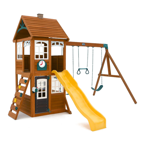
C E D A R S U M M I T P R E M I U M M A I N
C L U B H O U S E A N D S W I N G - F 2 4 9 4 5
INSTALLATION AND OPERATING INSTRUCTIONS
WARNING
FOR OBSTACLE FREE SAFETY ZONE AND MAXIMUM NUMBER OF USERS SEE - Fort Guides in Main Clubhouse and Swing or Add On C
instructions. See Page 3 for Protective Surfacing requirements.
MAXIMUM VERTICAL FALL HEIGHT FOR ALL FORTS - 6'9" Ages 3 to 10; Weight Limit 110 lbs. (49.9 kg) per child.
RESIDENTIAL HOME USE ONLY. Not intended for public areas such as schools, churches, nurseries, day cares or parks.
Required:
F24945 - Main Clubhouse and Swing
A24948 - High Rail Wave Slide
Required:
F24945 - Main Clubhouse and Swing
A24949 - TNRIII Tube Slide
9404945
To reduce the risk of serious injury or death, you must read and follow these instructions. Keep
and refer to these instructions often and give them to any future owner of this play system.
Manufacturer contact information provided below.
McKinley
Creston Lodge
Cedar Summit
c/o ©Solowave Design L.P.
Mount Forest, ON Canada
N0G 2L0
www.cedarsummitplay.com
support@cedarsummitplay.com
Customer Service
1-877-817-5682 (toll free)
1-519-323-2258
FORTS
10-14 Hrs
Two person
Required:
assembly
F24945 - Main Clubhouse and Swing
A24948 - High Rail Wave Slide
TUBE SLIDE
2-4 Hrs
Two person
Required:
assembly
F24945 - Main Clubhouse and Swing
A24948 - High Rail Wave Slide
A24949 - TNRIII Tube Slide
Willowbrook
Lewiston Retreat
Table of Contents
Warnings and Safe Play Instructions. . . . . . . . . . pg. 2
Protective Surfacing Guidelines . . . . . . . . . . . . . . . pg. 3
Instructions for Proper Maintenance . . . . . . . . . pg. 4
About Our Wood - Limited Warranty . . . . . . . . . pg. 5
Keys to Assembly Success . . . . . . . . . . . . . . . . . . . . pg. 6
Metric Conversion Sheets . . . . . . . . . . . . . . . . . . pg. 7,8
Part ID . . . . . . . . . . . . . . . . . . . . . . . . . . . . . . . . . . . . . . . . pg. 9
Installation of I.D./Warning Plaque . . . . . . . . . .pg. 59
Fort Guides . . . . . . . . . . . . . . . . . . . . . . . . . . . . . . pg. 60-67
Rev 02/04/2015
Advertisement
Table of Contents

Related Manuals for Cedar Summit McKinley


Summary of Contents for Cedar Summit McKinley
-
Page 1: Table Of Contents
MAXIMUM VERTICAL FALL HEIGHT FOR ALL FORTS - 6’9” Ages 3 to 10; Weight Limit 110 lbs. (49.9 kg) per child. RESIDENTIAL HOME USE ONLY. Not intended for public areas such as schools, churches, nurseries, day cares or parks. McKinley Willowbrook... -
Page 2: Warnings And Safe Play Instructions
Warnings and Safe Play Instructions CONTINUOUS ADULT SUPERVISION REQUIRED. Most serious injuries and deaths on playground equipment have occurred while children were unsupervised! Our products are designed to meet mandatory and voluntary safety standards. Complying with all warnings and recommendations in these instructions will reduce the risk of serious or fatal injury to children using this play system. -
Page 3: Protective Surfacing Guidelines
Protective Surfacing - Reducing Risk of Serious Head Injury From Falls One of the most important things you can do to reduce the likelihood of serious head injuries is to install shock-absorbing protective surfacing under and around your play equipment. The protective surfacing should be applied to a depth that is suitable for the equipment height in accordance with ASTM F1292. -
Page 4: Instructions For Proper Maintenance
Instructions for Proper Maintenance Your Cedar Summit Play System is designed and constructed of quality materials with your child’s safety in mind. As with all outdoor products used by children, it will weather and wear. To maximize the enjoyment, safety and life of your Play Set, it is important that you, the owner, properly maintain it. -
Page 5: About Our Wood - Limited Warranty
About Our Wood Cedar Summit Premium Play Systems uses only premium playset lumber, ensuring the safest product for your children’s use. Although we take great care in selecting the best quality lumber available, wood is still a product of nature and susceptible to weathering which can change the appearance of your set. -
Page 6: Keys To Assembly Success
Keys to Assembly Success Tools Required • Tape Measure • #1, #3 Phillips or Robertson • Open End Wrench • 3/16” Hex Key • Carpenters Level (1/2” & 7/16”) • 8’ Step Ladder bit or Screwdriver • Carpenters Square • Ratchet(1/2” & 7/16” •... -
Page 7: Metric Conversion Sheets
support@cedarsummitplay.com... - Page 8 support@cedarsummitplay.com...
-
Page 9: Part Id
Part Identification (Reduced Part Size) Part Identification (Reduced Part Size) Part Identification (Reduced Part Size) Part Identification (Reduced Part Size) 2pc. - 2717 - Clock Block 3/4 x 1-3/4 x 9-3/4" Nominal Size Actual Size Box 2 - 3632717 5/4 x 5 15/16 x 4-1/4 5/4 x 6 15/16 x 5-1/4... - Page 10 Part Identification (Reduced Part Size) 2pc. - 2618 Front Back 1pc. - 2627 1pc. - 2639 Panel 1¼ x 42 x 87" SW Wall Panel 1¼ x 42 x 87" Back Roof Panel 1¼ x 36¾ x 44" Box 2 - 37632618 Box 2 - 37632627 Box 2 - 37632639 1pc.
- Page 11 Hardware Identification (Actual Size) 10pc. TN1 - 1/4" T - Nut 5pc. FW0 - 3/16" Flat Washer - (51103100) 5pc. LW2 - 5/16" Lock Washer - (51303300) (54503200) 12pc. FW1 - 1/4" Flat Washer - (51103200) 8pc. TN2 - 5/16" T- Nut (54503300) 15pc.
- Page 12 Hardware Identification (Actual Size) Box 1,2 of 6 1/4 x 2-1/2" 16pc. WL5 - Wafer Lag Wafer Bolt 5/16 x 3" 3pc. WB7 - - (53613330) - (52613222) Hex Bolt 1/4 x 1-1/2" 4pc. H1 - - (53703212) Hex Bolt 1/4 x 2-3/4" 4pc.
- Page 13 1x - Clock Subset (3320329) 1x - Rebar Ground Stake (6 Pk) (3200318) 1x - Rocks (5pk) (3320386) 1x - Cedar Summit Plaque 2x - Jamb Mount (9320358) (9206300) 1x - Welded Chain Bag (3200170) Green 4x 9201254 54" chain -Green 2x 9201225 25"...
- Page 14 • The carton I.D. stamp is located on the end of each carton. The tracking number is located on the Cedar Summit ID Plaque (3320356). • Please retain this information for future reference. You will need this information if you contact the Consumer Relations Department.
- Page 15 Step 2: Frame Assembly Part 1 It is important to assemble the frame on a flat, smooth surface. A: Place (2627) SW Wall Panel between 2 (2618) Front Back Panels noticing the panel orientations. The tops and bottoms of the panels should be flush. Make sure the panels are square then using the pilot holes as a guide pre-drill with a 3/16”...
- Page 16 Step 2: Frame Assembly Part 2 B: Place (2622) End Panel Assembly between both (2618) Front Back Panels noticing the panel orientations. The tops and bottoms of the panels should be flush. Make sure the panels are square then using the pilot holes as a guide pre-drill with a 3/16”...
- Page 17 Step 3: Floor Assembly Part 1 A: From inside the assembly centre (2608) Floor Joist over pilot holes in (2622) End Panel Assembly and (2627) SW Wall Panel, 5/8” down from the top of board then attach (2608) Floor Joist to each panel with 2 (S4) #8 x 3” Wood Screws per end.
- Page 18 Step 3: Floor Assembly Part 2 B: On both (2618) Front Back Panels attach 1 (2610) Side Joist to the inside of each panel with 2 (H11) 1/4 x 2-3/4” Hex Bolts (with lock washer, flat washer and t-nut) and 4 (S3) #8 x 2-1/2” Wood Screws as shown in fig. 3.4 and 3.5.
- Page 19 Step 3: Floor Assembly Part 3 C: Starting at (2627) SW Wall Panel place (2648) Floor Board followed by 8 (2609) Floor Boards. Make sure all boards are evenly spaced then attach to (2608) Floor Joist and each (2610) Side Joist with 5 (S20) #8 x 1-3/8” Wood Screws per board.
- Page 20 Step 4: Attach SW Ground and Diagonal A: Loosely attach 1 (2606) SW Ground to each (2607) Diagonal with 1 (H10) 1/4 x 2-1/4” Hex Bolt (with lock washer, flat washer and t-nut) per board then place each (2607) Diagonal tight and flush to the front of (2627) SW Wall Panel.
- Page 21 Beam as shown in fig. 5.3. IT IS IMPORTANT THAT THIS BOLT IS ATTACHED. IT WILL MINIMIZE CHECKING OF WOOD. D: Attach Cedar Summit Plaque to centre of (2614) Engineered Beam (over top of t-nut) using 4 (S18) #6 x 1” Wood Screws. (fig. 5.4)
- Page 22 Step 6: Swing End Assembly A: Loosely attach 2 (2613) Heavy SW Posts to (2615) SW Upright using 2 (G7) 5/16 x 5-1/2” Hex Bolts (with lock washer, flat washer and t-nut). Notice 2 bolt holes at top of (2615) SW Upright and orientation of angle. (fig.
- Page 23 Step 7: Attach Swing End to Swing Beam A: Place Swing End Assembly against Swing Beam Assembly then place 1 Beam Bracket on each side of the assembly (they are specific for left and right side) and attach with 5 (G21) 5/16 x 3-3/4” Hex Bolts (with 2 flat washers and 1 lock nut).
- Page 24 Step 8: Attach Swing Assembly To Fort A: Place Swing Assembly against top of (2627) SW Wall Panel, make sure assembly is level then attach from inside the fort assembly into each L-Beam Bracket with 4 (G8) 5/16 x 2” Hex Bolts (with 2 flat washers and 1 lock nut).
- Page 25 Step 9: Install Ground Stakes MOVE FORT TO FINAL LOCATION PRIOR TO STAKING FINAL LOCATION MUST BE LEVEL GROUND A: In the 5 places shown in fig. 9.1 drive the Rebar Ground Stakes 13” into the ground against outside front corner of (2622) End Panel Assembly, on both (2607) Diagonals and both (2613) Heavy SW Posts.
-
Page 26: Fort Guides
Steps 10 - 29 show how to assemble and install add-ons and inserts. Fort Guides show where to install them. FORT GUIDES: Page 60-61: McKinley Page 62-63: Willowbrook Page 64-65: Creston Lodge Page 66-67: Lewiston Retreat support@cedarsummitplay.com... - Page 27 Step 10: How to Install Inserts - Upper and Lower Jambs There are 2 (2601) Lower Jambs and 1 (2602) Upper Jamb provided with the Main Clubhouse and Swing. Depending on which fort you have purchased determines where they are installed on the (2622) End Panel Assembly or (2618) Front Back Panel, see Fort Guide.
- Page 28 Step 11: How to Install Inserts - Window and Wall Inserts Part 1 There is 2 (2720) Lower Window Inserts, 2 (2719) Upper Window Inserts, 1 (2665) Half Wall Insert, 2 (649A) Short Half Walls and 1 MOD 3-Pane Transom provided with the Main Clubhouse and Swing. Depending on which fort you have purchased determines where they are installed, see Fort Guide.
- Page 29 Step 11: How to Install Inserts - Window and Wall Inserts Part 2 Inside Views 3-Pane Transom Tight 649A 2665 Tight Tight SIZE DWG. NO. REV. INSERT PANEL PREP SIZE DWG. NO. REV. Details Use 5- #8 x 7/8" Truss to attach Window + 4 -#8 x 7/8" to attach Flanges to wall panel ( first, install middle screw at top of Window) SCALE:1:50 WEIGHT:...
- Page 30 Step 12: How to Install Inserts - Clock Assembly There is 1 Clock Set provided with the Main Clubhouse and Swing. Depending on which fort you have purchased determines where it is installed, see Fort Guide. See below for how to assemble and attach the Clock Set. When installing you will need the following: Base Clock, Clock Subset (includes minute and hour hands, clock adapter and clock screw), 2 (2717) Clock Blocks and 4 x (S20) #8 x 1-3/8”...
- Page 31 Step 13: Rock Wall Assembly Fig. 13.1 Note: The holes in the rock boards 0349 must orient to the 2603 2603 2604 top of the boards. 2604 2604 2605 7-5/8” x 4 per Approx board Note: Gaps between boards 2-1/4”, not to exceed 2-3/8”...
- Page 32 Step 14: Attach Rock Wall Assembly to Fort Part 1 A: Place Rock Wall Assembly in opening shown on the Fort Guide and flush as shown below. Attach (0349) Rock Rails to panel using 4 (S11) #8 x 2” Wood Screws. (fig. 14.1 and 14.2) B: Attach 1 (2605) Access Board to top of Rock Wall Assembly, flush to top of (0349) Rock Rail using 4 (S20) #8 x 1-3/8”...
- Page 33 Step 14: Attach Rock Wall Assembly to Fort Part 2 C: Drive 1 Rebar Ground Stake 13” into the ground against outside (0349) Rock Rail then attach with 1 (S7) #12 x 2” Pan Screw. Be careful not to hit the washer while hammering stake into the ground as this could cause the washer to break off.
- Page 34 Step 15: Counter Assembly Part 1 A: Flush to each end and to the top of (2687) Counter Back attach 1 (5736) Counter Joist per end with 1 (S20) #8 x 1-3/8” Wood Screw per joist. Notice the remaining holes at the bottom of (2687) Counter Back. (fig. 15.1) B: Place the remaining 2 (5736) Counter Joists centred over the pilot holes in the middle of (2687) Counter Back and flush to the top of the board, then attach, in the top holes, with 1 (S20) #8 x 1-3/8”...
- Page 35 Step 15: Counter Assembly Part 2 C: On the inside of the panel shown in the Fort Guide place Counter Assembly so the top of (2687) Counter Back is flush to the top of the opening then attach with 5 (S20) #8 x 1-3/8” Wood Screws. (fig. 15.2 and 15.3) Fig.
- Page 36 Step 15: Counter Assembly Part 3 D: Place 1 (6136) Counter Brace flush to the front and outside edge of each outer (5736) Counter Joist and tight to the panel then attach with 2 (S3) #8 x 2-1/2” Wood Screws per brace. (fig. 15.4 and 15.5) Fig.
- Page 37 Step 15: Counter Assembly Part 4 E: Place (2686) Counter Front against (5736) Counter Joists so the ends are flush and the centre (5736) Counter Joists are centred over the pilot holes. Measure 5/8” down from the top of (2686) Counter Front on both ends and attach to the (5736) Counter Joists with 4 (S20) #8 X 1-3/8”...
- Page 38 Step 15: Counter Assembly Part 5 F: Tight to (2687) Counter Back attach (2685) Counter Top to each (5736) Counter Joist with 4 (TS) #6 x 30 mm Trim Screws. (fig. 15.7) G: Tight to (2685) Counter Top and flush to the outside edges of the outer (5736) Counter Joists attach 1 (5536) Counter Side per joist with 3 (TS) #6 x 30 mm Trim Screws per board.
- Page 39 Step 15: Counter Assembly Part 6 J: Place Faucet and 2 Sink Knobs in opening of Sink and attach Sink Knobs with included hardware. (fig. 15.9) Important: Use a hand held screw driver and DO NOT over tighten. Fig. 15.9 Faucet Sink Knob Sink Knob...
- Page 40 Step 15: Counter Assembly Part 7 K: Place Sink and Stove in the openings of the Counter Assembly then attach 4 Mount Clips with included hardware to the bottom of the Sink and Stove to secure in place. (fig. 15.10 and 15.11) Important: Use a hand held screw driver and DO NOT over tighten.
- Page 41 Step 16: Attach Utensil Shelf A: From inside the assembly, centred in the top of the opening of panel as shown in the Fort Guide, above the counter, attach Utensil Shelf with 2 (S13) #6 x 5/8” Pan Screws as shown in fig. 16.1 and 16.2. B: Attach Pot, Pan and Spatula to the Utensil Shelf.
- Page 42 Step 17: Attach Door Components Part 1 A: On the inside of (2718) Door Window Panel measure 15” up from the bottom and attach Catch Plate flush to the edge using 2 (S18) #6 x 1” Wood Screws. (fig. 17.1) B: On the inside of (2718) Door Window Panel measure 22”...
- Page 43 Step 17: Attach Door Components Part 2 C: On the outside of the (2718) Door Window Panel attach the second Door Handle at approximately the same place as the one on the inside. Use 2 (S13) #6 x 5/8” Pan Screws. (fig. 17.2) D: On the opposite side of the Door Handle measure 5/8”...
- Page 44 Step 18: Attach Door Assembly to Fort A: In the opening for the door as shown in the Fort Guides, measure 5/8” up from the bottom of the opening and maximum 5/8” from (2601) Lower Jamb or panel and attach the remaining side of the hinges to (2601) Lower Jamb or panel using 3 (S13) #6 x 5/8”...
- Page 45 Step 19: Attach Door Stop A: In the notched out opening of (2715) Door Stop attach the Magnetic Catch using 2 (S18) #6 x 1” Wood Screws. (fig. 19.1) Important: Use a hand held screw driver and DO NOT over tighten. B: On the inside of the assembly, attach (2715) Door Stop to the panel with 3 (S11) #8 x 2”...
- Page 46 Step 20: Attach Clicker Phone A: Using the Fort Guide to show location, on the (2601) Lower Jamb beside the Door Assembly install the Phone Base with 2 (S13) #6 x 5/8” Pan Screws then place the Clicker Phone in the Phone Base. (fig. 20.1 and 20.2) Fig.
- Page 47 Step 21: Attach Rural Mailbox Part 1 A: Using the Fort Guide to show location attach Mailbox Mount to fort with 3 (S10) #8 x 1” Pan Screws. (fig. 21.1) B: Attach Mailbox Door to Mailbox Bottom. (fig. 21.2) C: Using the screws provided with the mailbox set attach the sides together with 2 of the screws then attach the Flag to the side with the hole.
- Page 48 Step 21: Attach Rural Mailbox Part 2 E: Slide the Mailbox Assembly over the detents on the Mailbox Mount so the tabs are inserted into the Mailbox Bottom slots. This will lock it into place. (fig. 21.5, 21.6 and 21.7) Fig.
- Page 49 Step 22: Attach Slide to Fort Please note this slide is not used on the Creston Lodge Fort, please skip this step and refer to the instructions in the TNRIII Tube Slide box for assembly and installation. A: Place Slide in the centre of the opening as shown in the Fort Guide, pre-drill with a 1/8” drill bit then attach slide to fort through the panel using 3 (S7) #12 x 2”...
- Page 50 Step 23: Roof Support Assembly A: Attach 1 (2617) Roof Support to a second (2617) Roof Support at peak using 1 (S4) #8 x 3” Wood Screw. Repeat this step so there are 2 Roof Support Assemblies. (fig. 23.1 and 23.2) Roof Support Assembly Fig.
- Page 51 Step 24: Roof Assembly Part 1 A: Place (2644) Front Roof Panel against (2639) Back Roof Panel so the tops form a peak then tight to the inside edge of the outside slats attach 1 Narrow Angle Bracket per slat with 2 (S0) #8 x 7/8” Truss Screws per bracket.
- Page 52 Step 24: Roof Assembly Part 2 C: Place 1 Roof Support Assembly against one side so the peaks meet and the ends of the roof supports are flush with the ends of the roof panels. Attach with 6 (S11) #8 x 2” Wood Screws. (fig. 24.4) D: Attach the second Roof Support Assembly on the opposite side, peaks to meet and ends are flush with 6 (S11) #8 x 2”...
- Page 53 Step 25: Attach Peak Detail A: Attach 1 Peak Detail to the inside of the (2617) Roof Supports on each side of the Roof Assembly with 8 (S8) #12 x 3/4” Pan Screws (with 1/4” flat washer) per Peak Detail. (fig. 25.1 and 25.2) Peak Detail Fig.
- Page 54 Step 26: Chimney Wall Assembly Part 1 A: Bend the Chimney Wall to form a box and insert tabs into slots. (fig. 26.1 and 26.2) B: Place the (7567) Chimney Top on top of the assembly and attach with 4 (S13) #6 x 5/8” Pan Screws. (fig. 26.3, 26.4 and 26.5) Tabs Fig.
- Page 55 Step 26: Chimney Wall Assembly Part 2 C: Place the Chimney Wall Assembly centred on top of the Roof Assembly and attach with 2 (S13) #6 x 5/8” Pan Screws. (fig. 26.6 and 26.7) Chimney Assembly Fig. 26.6 Roof Assembly Chimney Assembly Fig.
- Page 56 Use the reference guides below to determine where the (2646) Roof End and (2647) Roof End Left are attached. For Willowbrook and Lewiston Retreat use Ref #1. For McKinley and Creston Lodge use Ref #2. Note the TNRIII Tube Slide must be assembled and attached before the Roof Ends. See TNRIII Tube Slide instructions.
- Page 57 Step 28: Attach Roof Assembly to Fort A: With 2 people on the ground and at least 1 person in the fort, lift the Roof Assembly up and over the Back side of the fort. Guide the Roof Assembly onto the fort so all four (2617) Roof Supports sit flush to the front and outside edges of (2646) Roof End and (2647) Roof End Left.
- Page 58 Step 29: Attach Acro and Belt Swings A: Using 1 Threaded Clip per chain, join 1 Long Swing Chain to each side of the swing belt seat. Make sure to close the Threaded Clip tightly using an adjustable wrench. (fig. 29.1 and 29.2). B: Using 1 Threaded Clip per chain, join the Short Swing Chain to the Acro Bar and Acro Handle.
-
Page 59: Installation Of I.d./Warning Plaque
4 (S13) #6 x 5/8” Pan Screws as shown below. Cedar Summit I.D. Plaque Hardware Other Parts 1 x Cedar Summit I.D. Plaque #6 x 5/8” Pan Screw support@cedarsummitplay.com... - Page 60 Fort Guide: McKinley MOD 3 Pane 2719 2618 Transom (Slide sold separately for instore purchases only) Front Clock MOD 3 2720 17” Pane 2719 17” Transom 2618 Clock Rural 2601 Mailbox Slide Clicker Position Phone Rural Mailbox 2720 Front Installation...
- Page 61 Fort Guide: McKinley 2618 Deluxe Kitchen Set 649A 17” 17” 2618 Back 649A 2601 649A 2720 2720 Back Installation 2601 Roof Assembly Roof Installation with Chimney Peak Detail 1 per side 26'- 3" 2647 1 per side 14'- 3" 11'-5"...
- Page 62 Fort Guide: Willowbrook 2719 2618 Clock Front 2601 2618 17” 17” 2720 2719 2719 Clock Rural Mailbox Clicker Position Phone 2720 Rural Front Installation Mailbox Door Assembly Door Assembly 2601 MOD 3-Pane Transom Slide sold separately for instore purchases only 2602 17”...
- Page 63 Fort Guide: Willowbrook 2618 MOD 3-Pane Transom 649A Back MOD 3-Pane Transom 2618 17” 649A 17” Rock Wall 2601 2720 Position Back Installation 2720 2601 Rock Wall Roof Installation Roof Assembly with Chimney Peak Detail 1 per side 30'- 4" 18'- 4"...
- Page 64 Fort Guide: Creston Lodge MOD 3-Pane 2618 Transom 2719 Clock Front 17” 17” MOD 3-Pane Transom 2719 2618 Clock 2601 Rock Wall Position Door Assembly Position 649A Clicker 649A Phone 2601 Door Front Installation Rock Wall Assembly MOD Side Lite 2602 Deluxe Kitchen Set...
- Page 65 Fort Guide: Creston Lodge MOD 3-Pane Transom 2618 649A 2719 MOD 3-Pane 17” 17” Transom 2601 Back 2719 649A Rural Mailbox 2618 Position 2720 2601 Rural Back Installation Mailbox 2720 Roof Installation Roof Assembly with Chimney Peak Detail 1 per side 28'-8"...
- Page 66 Fort Guide: Lewiston Retreat MOD 3-Pane 2618 Transom Clock Front 17” 17” MOD 3-Pane Transom 2719 2719 2618 Clock Slide 2601 Door Position Assembly 2720 2720 Rural Mailbox Clicker Rural Phone Mailbox Slide sold Position Front Installation separately for Door instore purchases 2601 Assembly...
- Page 67 Fort Guide: Lewiston Retreat MOD 3-Pane Transom 2719 2618 17” 17” MOD 3-Pane Transom Back 2719 2601 2601 Deluxe Kitchen Set 2618 2720 649A Rock Wall 2720 Position Back Installation 649A Rock Wall Roof Installation Roof Assembly with Chimney Peak Detail 1 per side 28'-8"...
- Page 68 NOTES support@cedarsummitplay.com...
- Page 69 NOTES support@cedarsummitplay.com...
- Page 70 BIG BACKYARD Consumer Registration Card First Name Initial Last Name Street Apt. No. City State/Province ZIP/Postal Code Country Telephone Number E-Mail Address Model Name Model Number (Box Labels) Serial Number (on ID Plaque) Date Purchase Purchased From MM / DD / YY How would you rate this product for quality? Excellent Very Good...
Need help?
Do you have a question about the McKinley and is the answer not in the manual?
Questions and answers
Are there any parts available for the tube slid
Yes, the context mentions Jamb Mounts (part numbers 2601 and 2602) and #8 x 7/8” Truss Screws (part number S0) as parts used for the tube slide installation location in the Creston Lodge and Lewiston Retreat variations.
This answer is automatically generated