Table of Contents
Advertisement
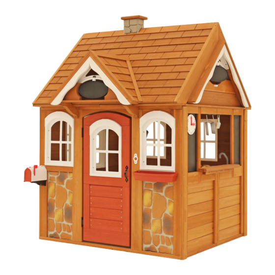
S T O N E Y C R E E K C E D A R P L AY H O U S E – P 2 8 0 0 9 0
INSTALLATION AND OPERATING INSTRUCTIONS
1422.4
56"
3 - 5 Hrs
TWO PERSON
ASSEMBLY
Instructional video available online: http://www.cedarsummitplay.com/install-stoneycreek
Rev 10/27/2016
9400090
WARNING
play set. Manufacturer contact information provided below.
CAPACITY - 5 Users Maximum, Ages 2 to 10.
1398.1
55"
RESIDENTIAL HOME USE ONLY. Not intended for public areas such as schools, churches, nurseries,
day cares or parks.
©
c/o
Solowave Design
Cedar Summit
375 Sligo Rd. West, PO Box 10
Mount Forest, ON Canada N0G 2L0
Regular Hours: 8:00am - 5:00pm EST
General Inquiries:
Peak Season (April - August):
8:00am - 7:00pm EST (Mon - Fri)
8:00am - 4:00pm EST (Sat & Sun)
Toll Free: 1-877-817-5682
Email: support@cedarsummitplay.com
Web Form/Line Chat:
To reduce the risk of serious injury or death, you must
read and follow these instructions. Keep and refer to these
instructions often and give them to any future owner of this
Table of Contents
Warnings And Safe Play Instructions . . . . . . . . . . .pg. 2
Instructions For Proper Maintenance . . . . . . . . . . .pg. 2
Keys To Assembly Success . . . . . . . . . . . . . . . . . . . . .pg. 3
About Our Wood – Limited Warranty. . . . . . . . . . .pg. 4
Keys to Quick Assembly . . . . . . . . . . . . . . . . . . . . . . .pg. 5
Part ID . . . . . . . . . . . . . . . . . . . . . . . . . . . . . . . . . . . . . . . . .pg. 6
Step-By-Step Instructions . . . . . . . . . . . . . . . . . . . . pg. 13
Installation of I.D./Warning Plaque . . . . . . . .Final Step
www.cedarsummitplay.com/contact-us
Advertisement
Table of Contents

Related Manuals for Cedar Summit STONEYCREEK CEDAR PLAYHOUSE P280090


Summary of Contents for Cedar Summit STONEYCREEK CEDAR PLAYHOUSE P280090
- Page 1 ASSEMBLY Instructional video available online: http://www.cedarsummitplay.com/install-stoneycreek © Solowave Design Cedar Summit 375 Sligo Rd. West, PO Box 10 Table of Contents Mount Forest, ON Canada N0G 2L0 Warnings and Safe Play Instructions ...pg. 2 Instructions for Proper Maintenance .
- Page 2 Instructions for Proper Maintenance Your Cedar Summit Play System is designed and constructed of quality materials with your child’s safety in mind. As with all outdoor products used by children, it will weather and wear. To maximize the enjoyment, safety and life of your Playhouse, it is important that you, the owner, properly maintain it.
- Page 3 Keys to Assembly Success Tools Required • Carpenters Level • Standard or Cordless Drill • Safety Glasses • Claw Hammer • Carpenters Square • Pencil • Adult Helpers • Tape Measure Part Identification Key Key Number: The first two digits 2X 012 Post 2 x 4 x 83”...
- Page 4 About Our Wood Cedar Summit Premium Play Systems uses only premium playset lumber, ensuring the safest product for your children’s use. Although we take great care in selecting the best quality lumber available, wood is still a product of nature and susceptible to weathering which can change the appearance of your set.
- Page 5 Your Key To Quick Assembly SORTING WOOD PARTS INTO EACH ASSEMBL Y STEP WILL SAVE TIME! Step Step Step SAVE TIME - TIP #1: Open box with wood parts and look for the Key Number stamped on the end of the wood part (see chart below). Sort each wood part into the different assembly steps.
- Page 6 support@cedarsummitplay.com...
- Page 7 support@cedarsummitplay.com...
- Page 8 Part Identification (Reduced Part Size) Part Identification (Reduced Part Size) Part Identification (Reduced Part Size) Part Identification (Reduced Part Size) 48045336 (1 x 1 x 19") (3) 043 - 25.4 x 25.4 x 482.6 - Panel Tie FSC - 48046036 (5/8 x 1‐3/8 x 41‐3/4") (1) 071 - 15.9 x 34.9 x 1060.4 - Counter Top FSC - (4) 110 - 12.7 x 57.2 x 1063.6 - Corner Trim FSC - 48046736 (1/2 x 2‐1/4 x 41‐7/8") 48045936 (5/8 x 2‐3/4 x 41‐3/4")
- Page 9 Part Identification (Reduced Part Size) Part Identification (Reduced Part Size) Part Identification (Reduced Part Size) Part Identification (Reduced Part Size) (1 x 5 x 8‐1/4") (2) 181 25.4 x 127 x 209.6 - Dormer Spacer FSC- 48061236 (1) 024 31.8 x 82.6 x 323.9 - Dormer Cleat FSC - 48064536 (1‐1/4 x 3‐1/4 x 12‐3/4") (5/8 x 2 x 19‐13/32") (2) 190 15.9 x 50.8 x 677.8 - Dormer Gingerbread FSC - 48061605...
- Page 10 Part Identification (Reduced Part Size) Part Identification (Reduced Part Size) Part Identification (Reduced Part Size) Part Identification (Reduced Part Size) 478059736 (1‐1/4 x 36 x 48‐1/2") (1) 022 31.8 x 914.4 x 1231.9 - Roof Front FSC - (1) 171 31.8 x 490.1 x 524.7 (1‐1/4 x 19‐1/4 x 20‐7/8") Dormer Panel - Right FSC 478062036...
- Page 11 Hardware Identification (Actual Size) 2pc. FW0 - 3/16" Flat Washer - (51103100) #12 x 1" 2pc. S6 - Pan Screw (52433610) #7 x 5/8" 104pc. S37 - Pan Screw - (52433009) #7 x 1-1/8" 51pc. S38 - Wood Screw - (52433014) #8 x 1-3/4"...
- Page 12 Part Identification (Reduced Part Size) 1x - Door Bell 2/Door Trim (3323645) 1x - Playhouse Plaque (9320360) 1x - Chimney Wall (9320806) 3x - Narrow Angle Bracket (2 Pk) (3200639) 1x - Deluxe Kitchen Set (3320969) 1x - Stove (3320738) 1x - Utensils Shelf (9320791) 1x - Deep Window (5Pk)
- Page 13 Step 1: Inventory Parts - Read This Before Starting Assembly STOP STOP STOP STOP This is the time for you to inventory all your hardware, wood and accessories, referencing the parts identification sheets. This will assist you with your assembly. •...
- Page 14 Step 2: Roof Assembly Part 1 A: Attach 1 (021) Roof Side to another flush at the peak using 2 (S3) #8 x 2-1/2” Wood Screws. Do this twice so you have 2 Roof Support Assemblies. (fig. 2.1) Fig. 2.1 Wood Parts Hardware #8 x 2-1/2”...
- Page 15 Step 2: Roof Assembly Part 2 B: Place (022) Roof Front and (023) Roof Back tight together at the peak so (022) Roof Front overlaps (023) Roof Back. From underneath the Roof Assembly centre 1 Narrow Angle Bracket on each Joist and attach with 2 (S37) #7 x 5/8”...
- Page 16 Step 2: Roof Assembly Part 3 C: Place Roof Panel Assembly against each of the Roof Support Assemblies so the bottoms are flush and they meet at the peak. (fig. 2.5, 2.6 and 2.7) D: Attach each Roof Support Assembly to the Roof Panel Assembly with 6 (S15) #8 x 1-3/4” Wood Screws per side.
- Page 17 Step 2: Roof Assembly Part 4 Fig. 2.8 E: On the inside of the assembly on (022) View from Underneath Roof Front find the centre point then on the 4th siding up from the bottom, measure 1-1/2” up from bottom of siding and 2” on each side of the centre line.
- Page 18 Step 3: Counter Assembly Part 1 A: Flush to each end and to the bottom of (031) Counter Back attach 1 (033) Counter Joist per end with 1 (S2) #8 x 1-1/2” Wood Screw per joist. Notice the holes at the top of (031) Counter Back. (fig. 3.1 and 3.2) B: Place the remaining 3 (033) Counter Joists centred over the pilot holes in the middle of (031) Counter Back and flush to the bottom of the board.
- Page 19 Step 3: Counter Assembly Part 2 D: Place 1 (034) Counter Brace tight to the bottom of each outside (033) Counter Joist, tight to (032) Counter Front and attach using 1 (S3) #8 x 2-1/2” Wood Screw per brace. (fig. 3.3 and 3.4) E: Place (035) Counter Brace Centre tight to the bottom of the centre (033) Counter Joist, tight to (032) Counter Front and attach using 1 (S3) #8 x 2-1/2”...
- Page 20 Step 4: Frame Assembly Part 1 A: Stand (040) Panel Assembly up so window openings are at the top then with a helper at the opposite end open (040) Panel Assembly all the way so corners are at a 90 degree angle. (fig. 4.1 and 4.2) Fig.
- Page 21 Step 4: Frame Assembly Part 2 B: Flush to the inside face of the Side Wall and Cafe Wall place 1 (041) Soffit End centred in each opening and attach with 6 (S2) #8 x 1-1/2” Wood Screws per board. Notice the holes are towards the inside of the frame. (fig. 4.3) C: On the Door Wall and Back Wall, tight to each (041) Soffit End and flush to the inside face of each wall attach 2 (042) Soffit Wides to each wall with 4 (S2) #8 x 1-1/2”...
- Page 22 Step 4: Frame Assembly Part 3 E: Flush to the bottom and centred on the Side Wall and Cafe Wall attach 1 (043) Panel Tie to each wall with 4 (S15) #8 x 1-3/4” Wood Screws per board. (fig. 4.4, 4.5 and 4.6) Fig.
- Page 23 Step 5: Cafe Wall Assembly Part 1 A: Place (051) Cafe Table Top in large opening of Cafe Wall so the grooves are tight to the wall and attach with 2 (S15) #8 x 1-3/4” Wood Screws in the outside holes. (fig. 5.1 and 5.2) B: Centred and tight to the bottom of (051) Cafe Table Top attach (043) Panel Tie to Cafe Wall with 4 (S15) #8 x 1-3/4”...
- Page 24 Step 5: Cafe Wall Assembly Part 2 D: From inside the assembly, centred in the large opening of the Cafe Wall attach Utensil Shelf with 2 (S37) #7 x 5/8” Pan Screws as shown in fig. 5.3, 5.4 and 5.5. E: Attach Pot, Pan and Spatula to the Utensil Shelf.
- Page 25 Step 6: Attach Door Panel Accessories Part 1 A: Measure 18-1/4” up from the bottom of the Door on the outside and inside and attach 1 Door Handle per side using 2 (S37) #7 x 5/8” Pan Screws per handle. (fig. 6.1 and 6.2) B: Measure 15”...
- Page 26 Step 6: Attach Door Panel Accessories Part 2 C: In the notched out opening of (061) Door Latch Block attach Fig. 6.4 the Magnetic Catch using 2 (S38) #7 x 1-1/8” Pan Screws. (fig. Inside View 6.3 and 6.4) Important: Use a hand held screw driver and DO NOT over tighten.
- Page 27 Step 7: Attach Counter Assembly Part 1 A: On the inside of the playhouse assembly place Counter Assembly from Step 3 against the Cafe Wall. The top of (031) Counter Back should be flush and level to the bottom of (051) Cafe Table Top. (fig. 7.1 and 7.2) B: Attach (031) Counter Back to Cafe Wall with 4 (S2) #8 x 1-1/2”...
- Page 28 Step 7: Attach Counter Assembly Part 2 D: Tight to (031) Counter Back attach (071) Counter Top to each (033) Counter Joist with 5 (S38) #7 x 1-1/8” Pan Screws. (fig. 7.3) E: Tight to (071) Counter Top and flush to the outside edges of the outer (033) Counter Joists attach 1 (072) Counter Side per joist with 3 (S38) #7 x 1-1/8”...
- Page 29 Step 7: Attach Counter Assembly Part 3 G: Place Faucet and 2 Sink Knobs in opening of Sink and attach Sink Knobs with included hardware. (fig. 7.4) Important: Use a hand held screw driver and DO NOT over tighten. Fig. 7.4 Faucet Sink Knob Sink Knob...
- Page 30 Step 7: Attach Counter Assembly Part 4 H: Place Sink and Stove in the openings of the Counter Assembly then attach 4 Mount Clips with included hardware to the bottom of the Sink and Stove to secure in place. (fig. 7.5 and 7.6) Important: Use a hand held screw driver and DO NOT over tighten.
- Page 31 Step 8: Attach Dormer Gussets A: On the Door Wall place 1 (080) Dormer Gusset tight against the panel on both sides of the Door and centred under the pilot holes in each (042) Soffit Wide. From the top attach with 1 (S2) #8 x 1-1/2” Wood Screw per gusset and from the bottom attach with 1 (S3) #8 x 2-1/2”...
- Page 32 Step 9: Attach Roof to Assembly Make sure assembly is square before proceeding in this Step. A: With an adult helper lift the Roof Assembly from Step 2 onto the (042) Soffit Wides so the ends of each (021) Roof Side overhangs each (042) Soffit Wide by 1/4”. The opening should face the Side and Cafe Walls (fig. 9.1 and 9.2) B: Attach each (042) Soffit Wide to Roof Assembly with 2 (S2) #8 x 1-1/2”...
- Page 33 Step 10: Bay Window Assembly Part 1 A: From outside the assembly place Bay Window Bottom in the opening of the Side Wall as shown in fig. 10.1. Attach with 4 (S37) #7 x 5/8” Pan Screws. Fig. 10.1 Outside View Window Bottom Side Wall...
- Page 34 Step 10: Bay Window Assembly Part 2 B: Bend Bay Window Insert so it is curved and from inside the assembly place into the opening on top of the Bay Window Bottom as shown in fig. 10.2, 10.3 and 10.4. Attach with 4 (S37) #7 x 5/8” Pan Screws. The sides of the Bay Window Insert should fit tight to the inside of the wall panel.
- Page 35 Step 10: Bay Window Assembly Part 3 D: From outside the assembly place Bay Window Top on top of Bay Window Insert and under the wall panel then attach to Bay Window Insert with 4 (S37) #7 x 5/8” Pan Screws. (fig. 10.6, 10.7 and 10.8) E: Attach Bay Window Top to the Side Wall with 4 (S37) #7 x 5/8”...
- Page 36 Step 11: Attach Corner Trim A: Flush to the bottom and outside edges of the Cafe Wall attach 2 (110) Corner Trims with 6 (S38) #7 x 1-1/8” Pan Screws per board. (fig. 11.1 and 11.2) Repeat Step A for Side Wall. Notice hole orientation Fig.
- Page 37 Step 12: Cafe Gable Assembly Part 1 A: From inside the assembly, centred on the Cafe Wall place (121) Gable End tight to (042) Soffit Wides and (021) Roof Sides then attach with 4 (S2) #8 x 1-1/2” Wood Screws. (fig. 12.1) B: Tight to (121) Gable End place (120) Long Cafe Gable so the ends are flush and the arch is facing up then attach with 4 (S2) #8 x 1-1/2”...
- Page 38 Step 12: Cafe Gable Assembly Part 2 Fig. 12.2 C: From outside the assembly tight to (120) Long Outside View Cafe Gable and (121) Gable End place 2 (122) Cafe Roofs with the angled edges at the top and they form a peak.
- Page 39 Step 12: Cafe Gable Assembly Part 3 E: From inside the assembly measure 3” up from (120) Long Cafe Gable, place (123) Short Cafe Gable against the (021) Roof Sides with arch facing down and centred on assembly then attach with 4 (S2) #8 x 1-1/2” Wood Screws (fig.
- Page 40 Step 12: Cafe Gable Assembly Part 4 F: Insert Roof Peak Spin Sign into slot of Roof Peak Mount. (fig. 12.7) then place Roof Peak Mount in opening above (123) Short Cafe Gable tight to the peak. From outside the assembly attach Roof Peak Mount to each (122) Cafe Roof with 4 (S37) #7 x 5/8”...
- Page 41 Step 12: Cafe Gable Assembly Part 5 H: Measure 7/16” in from the front edge of each (122) Cafe Roof, place 1 (124) Cafe Gingerbread at each measured spot, tight to the peak and tight to each other then attach with 3 (S2) #8 x 1-1/2” Wood Screws per board.
- Page 42 Step 13: Side Wall Gable Assembly Part 1 A: On the outside of the assembly place Small Gable Vent between 2 (021) Roof Sides on the Side Wall tight to the peak then from the inside attach with 4 (S37) #7 x 5/8” Pan Screws. (fig. 13.1, 13.2 and 13.3) Fig.
- Page 43 Step 13: Side Wall Gable Assembly Part 2 B: Place (130) Roof Gable Support tight to both (021) Roof Sides and Small Gable Vent then attach with 2 (S2) #8 x 1-1/2” Wood Screws. (fig 13.4 and 13.5) C: From inside the assembly attach Small Gable Vent to (130) Roof Gable Support with 2 (S37) #7 x 5/8 Pan Screws.
- Page 44 Step 13: Side Wall Gable Assembly Part 3 D: From inside the assembly, centred in the opening and tight to the top of Side Wall panel and (042) Soffit Wides place (131) Gable End then attach to both (021) Roof Sides with 4 (S2) #8 x 1-1/2” Wood Screws. (fig 13.6) E: Tight to the top of (131) Gable End place (132) Gable End Short then attach to both (021) Roof Sides with 4 (S2) #8 x 1-1/2”...
- Page 45 Step 14: Attach Windows A: Place 1 Deep Window in each window opening on the Door Wall and Back Wall. There should be 5 Deep Windows in total, 3 on the Door Wall and 2 on the Back Wall. Attach each window with 4 (S37) #7 x 5/8” Pan Screws.
- Page 46 Step 15: Attach Flower Box A: Place 1 Flower Box under one Deep Window on the Door Wall as shown in fig. 15.1 then attach with 2 (S10) #8 x 1” Pan Screws. (fig. 15.1 and 15.2) Fig. 15.1 Door Wall Fig.
- Page 47 Step 16: Attach Rural Mail Box Part 1 A: Place both Mailbox Halves together and attach at the top with included hardware. (fig. 16.1) B: Snap Mailbox Door onto Mailbox Mount. (fig. 16.1) C: Place assembled Mailbox on Mailbox Mount and slide into place using the tabs and slots. (fig. 16.1) D: Attach Mailbox Flag to Mailbox with included hardware.
- Page 48 Step 16: Attach Rural Mail Box Part 2 E: On the outside corner of the Door Wall as shown in fig. 16.2 place Rural Mail Box Assembly on the panel then attach with 1 (S10) #8 x 1” Pan Screw from the bottom and 2 (S10) #8 x 1” Pan Screws on the top. (fig. 16.2, 16.3 and 16.4) F: For the remaining 2 holes, attach with 2 (S37) #7 x 5/8”...
- Page 49 Step 17: Dormer Panel Assembly A: Place (170) Dormer Panel Left tight to (171) Dormer Panel Right then attach with 1 Narrow Angle Bracket using 2 (S37) #7 x 5/8” Pan Screws. (fig. 17.1 and 17.2) Narrow Angle Bracket Fig. 17.1 Fig.
- Page 50 Step 18: Dormer Bottom Assembly A: Measure 7/8” in from the edge of (180) Dormer Bottom then place 1 (181) Dormer Spacer at each end of (180) Dormer Bottom flush to the angled ends and attach with 2 (S2) #8 x 1-1/2” Wood Screws per spacer. (fig. 18.1 and 18.2) Flush Fig.
- Page 51 Step 19: Dormer Assembly Part 1 A: Insert Roof Peak Spin Sign into slot of Roof Peak Mount (fig. 19.1) then place Roof Peak Mount in opening of Dormer Panel Assembly tight to the peak and flush to the inside edges. Attach Roof Peak Mount to (170) Dormer Panel Left and (171) Dormer Panel Right with 4 (S37) #7 x 5/8”...
- Page 52 Step 19: Dormer Assembly Part 2 B: Place Dormer Bottom/Spacer Assembly tight to inside edges of Dormer Panel Assembly feeding Roof Peak Spinner into hole of (180) Dormer Bottom. Attach Dormer Panel Assembly to each (181) Dormer Spacer with 2 (S15) #8 x 1-3/4”...
- Page 53 Step 19: Dormer Assembly Part 3 C: Tight to the peak and flush to the front edge of the Dormer Panel Assembly place 2 (190) Dormer Gingerbreads tight to each other at the top then attach with 3 (S15) #8 x 1-3/4” Wood Screws per board. (fig. 19.4) Fig.
- Page 54 Step 20: Attach Dormer Assembly to Roof Part 1 A: Place Dormer Panel Assembly on the Roof Assembly at the (024) Dormer Cleat then attach with 2 (S3) #8 x 2-1/2” Wood Screws. (fig. 20.1 and 20.2) Fig. 20.1 Parts Removed for Clarity Roof Assembly...
- Page 55 Step 20: Attach Dormer Assembly to Roof Part 2 B: Attach each (080) Dormer Gusset to (180) Dormer Bottom with 1 (S2) #8 x 1-1/2” Wood Screw per gusset. (fig. 20.3 and 20.4) Fig. 20.3 Fig. 20.4 Hardware #8 x 1-1/2” Wood Screw Instructional video: http://www.cedarsummitplay.com/install-stoneycreek support@cedarsummitplay.com...
- Page 56 Step 21: Chimney Wall Assembly Part 1 A: Bend the Chimney Wall to form a box and insert tabs into slots. (fig. 21.1 and 21.2) B: Place the (210) Chimney Top on top of the assembly and attach with 4 (S37) #7 x 5/8” Pan Screws. (fig. 21.3, 21.4 and 21.5) Tabs Fig.
- Page 57 Step 21: Chimney Wall Assembly Part 2 C: On top of the Roof Assembly measure 17-1/2” in from Side Wall then place the Chimney Wall Assembly on top of the Roof Assembly as shown in fig. 21.6 and attach with 2 (S37) #7 x 5/8” Pan Screws. (fig. 21.6 and 21.7) Chimney Assembly Fig.
- Page 58 Step 22: Attach Playhouse Plaque A: On the Side Wall below the Small Gable Vent install the Playhouse Plaque with 2 (S37) #7 x 5/8” Pan Screws. (fig. 22.1 and 22.2) Playhouse Plaque Fig. 22.2 Small Gable Vent Fig. 22.1 Side Wall Hardware Other Parts...
- Page 59 NOTES Instructional video: http://www.cedarsummitplay.com/install-stoneycreek support@cedarsummitplay.com...
- Page 60 Online Parts Replacement and Warranty Registration: Fill out your registration card online at Solowave Design www.cedarsummitplay.com/parts-center-warranty-claim/ www.cedarsummitplay.com/registration 375 Sligo Road W. Mount Forest, Ontario, Canada Cedar Summit would like to say Thank You for N0G 2L0 your time and feedback. Attention: Customer Service REVISION: 11/28/12...
Need help?
Do you have a question about the STONEYCREEK CEDAR PLAYHOUSE P280090 and is the answer not in the manual?
Questions and answers