Advertisement
Quick Links
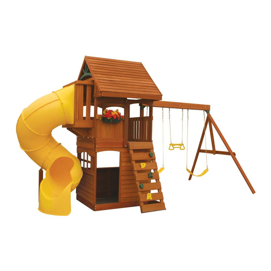
GRANDview Deluxe PlAY SYSTeM - F24730
INSTALLATION AND OPERATING INSTRUCTIONS
28'-1"
7'-4"
16'-1"
Grandview
height: 9feet - 6"
Length: 16feet -1"
Width: 7feet - 4"
10-14 Hrs
Two person
assembly
3404730
WARNING
and give them to any future owner of this play system. Manufacturer contact information provided below.
OBSTACLE FREE SAFETY ZONE - 28'1" x 26'6" area requires Protective Surfacing. See page 3.
26'-6"
MAXIMUM VERTICAL FALL HEIGHT - 6'5"
CAPACITY - 9 Users Maximum, Ages 3 to 10; Weight Limit 110 lbs. (49.9 kg) per child.
RESIDENTIAL HOME USE ONLY. Not intended for public areas such as schools, churches, nurseries, day cares or parks.
Cedar Summit c/o ©Solowave Design Inc.
Mount Forest, ON Canada N0G 2L1
www.cedarsummitplay.com
support@cedarsummitplay.com
Customer Service
1-877-817-5682 (toll free)
To reduce the risk of serious injury or death, you must read and
follow these instructions. Keep and refer to these instructions often
Table of Contents
Warnings and Safe Play Instructions. . . . . . . . . . . . . . . pg. 2
Protective Surfacing Guidelines. . . . . . . . . . . . . . . . . . . pg. 3
Instructions for Proper Maintenance . . . . . . . . . . . . . . . pg. 4
About Our Wood - Limited Warranty . . . . . . . . . . . . . . pg. 5
Keys to Assembly Success . . . . . . . . . . . . . . . . . . . . . . pg. 6
Metric Conversion Sheets . . . . . . . . . . . . . . . . . . . . . pg. 7,8
Part ID . . . . . . . . . . . . . . . . . . . . . . . . . . . . . . . . . . . . . . . pg. 9
Installation of I.D./Warning Plaque . . . . . . . . . . . .Final Step
Rev 02/17/2012
Advertisement

Related Manuals for Cedar Summit GRANDVIEW DELUXE PLAY SYSTEM F24730


Summary of Contents for Cedar Summit GRANDVIEW DELUXE PLAY SYSTEM F24730
-
Page 1: Table Of Contents
Two person assembly Table of Contents Cedar Summit c/o ©Solowave Design Inc. Mount Forest, ON Canada N0G 2L1 Warnings and Safe Play Instructions....pg. 2 Protective Surfacing Guidelines....pg. 3 www.cedarsummitplay.com... -
Page 2: Warnings And Safe Play Instructions
Warnings and Safe Play Instructions CONTINUOUS ADULT SUPERVISION REQUIRED. Most serious injuries and deaths on playground equipment have occurred while children were unsupervised! Our products are designed to meet mandatory and voluntary safety standards. Complying with all warnings and recommendations in these instructions will reduce the risk of serious or fatal injury to children using this play system. -
Page 3: Protective Surfacing Guidelines
support@cedarsummitplay.com... -
Page 4: Instructions For Proper Maintenance
support@cedarsummitplay.com... -
Page 5: About Our Wood - Limited Warranty
support@cedarsummitplay.com... -
Page 6: Keys To Assembly Success
Keys to Assembly Success Tools Required Shovel Measuring Drill (1/8” Safety Hammer Ratchet 1/2”, Level #2 & #3 Phillips Square Step Tape 3/16” Bit) Glasses 7/16” & 9/16” or Robertson Ruler Ladder Part Identification Key 1234 Post 2 x 4 x 83” On each page, you will find the parts and quantities required to complete the assembly step illustrated on that page. -
Page 7: Metric Conversion Sheets
support@cedarsummitplay.com... - Page 8 support@cedarsummitplay.com...
-
Page 9: Part Id
Part Identification (Reduced Part Size) Part Identification (Reduced Part Size) Part Identification (Reduced Part Size) Nominal Size Actual Size 12pc. - 1800 CE Siding (3/8 x 3-1/2 x 25-1/2") - Box 1 - 3631800 1" x 2" ⅝" x 1⅜" 1"... - Page 10 Part Identification (Reduced Part Size) Part Identification (Reduced Part Size) Part Identification (Reduced Part Size) Actual Size Nominal Size 4pc. - 1975 Cedar Wall (1 x 4 x 29") - Box 3 - 3631975 1" x 6" ⅝" x 5⅜" 5/4"...
- Page 11 Part Identification (Reduced Part Size) Part Identification (Reduced Part Size) Part Identification (Reduced Part Size) Actual Size Nominal Size 2pc. - 1853 Cedar Gap Board (1 x 5 x 38-3/4") - Box 1- 3631853 1" x 6" ⅝" x 5⅜" 5/4"...
- Page 12 Part Identification (Reduced Part Size) Part Identification (Reduced Part Size) Part Identification (Reduced Part Size) Actual Size Nominal Size 2pc. - 1981 Crowsnest Joist (5/4 x 3 x 12-1/2") - Box 3 - 3641981 1" x 6" ⅝" x 5⅜" 5/4"...
- Page 13 Part Identification (Reduced Part Size) Part Identification (Reduced Part Size) Part Identification (Reduced Part Size) Actual Size Nominal Size 1pc. - 0369 Lower Diagonal (2 x 3 x 37") - Box 1 - 3640369 1" x 6" ⅝" x 5⅜" 5/4"...
- Page 14 Part Identification (Reduced Part Size) Part Identification (Reduced Part Size) Part Identification (Reduced Part Size) Nominal Size Actual Size 2pc. - 1952 Long Post (2 x 4 x 92-3/8") - Box 1 - 3641952 2" x 4" 1⅜" x 3⅜" 2"...
- Page 15 Hardware Identification (Actual Size) 1/4 x 3" 1/4 x 1-1/2" 7pc. LS3 - Lag Screw - (9262230) 4pc. LS1 - Lag Screw - (9262212) Hex Bolt 1/4 x 2" Hex Bolt 1/4 x 4" 24pc. H2 - - (9277220) 2pc. H4 - - (9277240) Hex Bolt 1/4 x 2-3/4"...
- Page 16 Hardware Identification (Actual Size) 56pc. TN1 - 1/4" T - Nut (9285200) 14pc. LW2 - 5/16" Lock Washer - (9253300) 18pc. FW3 - #8 Flat Washer - (9251500) 61pc. LW1 - 1/4" Lock Washer - (9253200) 39pc. FW0 - 3/16" Flat Washer - (9251100) 14pc.
- Page 17 9X 3310221 TNR2 Post Mount TNR2 Slide Elbow Yellow Yellow 1X 3202001 Swing Hanger Bolt Thru. (6 pk) 1X 9320357 Cedar Summit I.D. Plaque 2X 3320121 Peak Detail 1X 3310224 Green 1X 3310222 TNR2 Slide Exit Top TNR2 Slide Lt Flange...
- Page 18 Step 1: Inventory Parts - Read This Before Starting Assembly STOP STOP STOP STOP T his is the time for you to inventory all your hardware, wood and accessories, referencing the parts identification sheets. This will assist you with your assembly. • T he wood pieces will have the four digit key number stamped on the ends of the boards. The wood pieces are referenced throughout the instructions with this number. • Please refer to Page 6 for proper hardware assembly. • E ach step indicates which bolts and/or screws you will need for assembly, as well as any flat washers, lock washers, t-nuts or lock nuts. I f there are any missing or damaged pieces or you need assistance with assembly please contact the Consumer Relations Department directly. Call us before going back to the store. 1-877-817-5682 support@cedarsummitplay.com R ead the assembly manual completely, paying special attention to ANSI warnings; C. notes; and safety/maintenance information on pages 1 - 6. B efore you discard your cartons fill out the form below. D. • T he carton I.D. stamp is located on the end of each carton. The tracking number is located on the Cedar Summit ID Plaque (9320357).
- Page 19 Step 2: Rock Wall Assembly Fig. 2.1 0630 0630 0630 Note: The holes in the rock boards 0606 0349 must orient to the 0631 0631 top of the boards. Note: Gaps between boards 2-1/4”, 7-3/4” not to exceed 2-3/8” Approx A: Lay 2 (0349) Rock Rails down, side by side with angled edges facing down. (fig. 2.1) B: Place (0606) CE Access Board on the bottom of each (0349) Rock Rail as shown in fig. 2.1. Make sure (0606) CE Access Board is flush to the outside and bottom edges of each (0349). Attach using 4 (S2) #8 x 1-1/2” Wood...
- Page 20 Step 3: Swing Beam Assembly Warning: For your child’s safety, Fig. 3.4 orientate the swing hangers as shown to ensure your swing will have proper swing motion when installed. Failure to do so could result in premature failure of the swing hanger or swing chain.
- Page 21 Step 4: Swing End Assembly A: Attach 2 (1863) SW Posts to (1856) SW Upright using 2 (G4) 5/16 x 4” Hex Bolts (with lock washer, flat washer and t-nut). (fig. 4.1) Fig. 4.1 5/16” Lock Washer 1863 1862 1856 5/16” Flat Washer 5/16” T-Nut 5/16” Flat 5/16” Washer T-Nut 5/16” Lock Washer 1863 B: Attach (1862) SW Support to both (1863) SW Posts and (1856) SW Upright using 3 (G5) 5/16 x 4-1/2” Hex Bolts (with lock washer, flat washer and t-nut). (fig. 3.1) Wood Parts Hardware 5/16 x 4” Hex Bolt SW Post 2 x 4 x 86-11/16” 1863 (5/16”...
- Page 22 Step 5: Attach Swing End to Swing Beam A: Place (4919) SW Rail Block in the centre between (1826) Front Beam and (1825) Back Beam and attach with 1 (H8) 1/4 x 4-1/4” Hex Bolt (with lock washer, flat washer and t-nut). (fig. 5.1 & 5.2) 1826 Fig. 5.1 Fig. 5.2 1/4” Lock Washer 1826 1825 4919 1/4” Flat Washer 1825 1/4” T-Nut B: Attach Swing Beam Assembly to the side of the Swing End Assembly with the overhang (fig. 5.3 & 5.4) using 1 (G5) 5/16 x 4-1/2” Hex Bolt (with lock washer, flat washer and t-nut) in the top hole of Triangle Plate and 1 (G8) 5/16 x 2” Hex Bolt (with 2 flat washers and lock nut) in the bottom hole of Triangle Plate. (fig. 5.4) Make sure Swing End Assembly flares out at an angle. (fig. 5.3) 1826 5/16” Lock 5/16” Flat Fig. 5.4 Washer Washer Fig. 5.3 Side with overhang 1825 5/16”...
- Page 23 Step 6: Roof Assembly Part 1 A: Attach 1 (0863) Roof Support to another at the peak using 1 (S4) #8 x 3” Wood Screw. (fig. 6.1) B: Attach 1 (1950) Roof Support Left to 1 (1951) Roof Support Right at the peak using 1 (S4) #8 x 3” Wood Screw. (fig. 6.1) C: Attach 1 (0501) Joist to another at the peak using 1 (S4) #8 x 3” Wood Screw. (fig. 6.1) D: Place the Roof Supports and Joist Assemblies in the pattern shown in fig. 6.1. Once in the pattern check that the assemblies have the same angles. Fig. 6.1 0863 0863 0501 0501 1951 1950 Wood Parts Hardware Joist 2 x 2 x 43-1/2” 0501 #8 x 3” Wood Screw Roof Support 2 x 3 x 43-1/2” 0863 Roof Support Right 2 x 3 x 43-1/2”...
- Page 24 Step 6: Roof Assembly Part 2 D: Starting at the top of the Roof Support Assembly and working down attach 3 (0517) Cedar Roofing on one side of the Roof Supports and (0501) Joists with 3 (S0) #8 x 7/8” Truss Screws per board. (fig. 6.2) Be sure to overlap the Cedar Roofing as shown in fig. 18.4. E: Repeat Step A for the other side of the Roof Support Assembly. F: Drill a hole 1-1/2” above the factory drilled holes in 2 (0517) Cedar Roofing. Attach 1 (0517) Cedar Roofing at the bottom of the Roof Support Assembly on each side, making sure they are flush to each Roof Supports with 3 (S0) #8 x 7/8” Truss Screws. (fig. 6.2 and 6.4) G: Evenly space and attach the remaining (0517) Cedar Roofing, leaving no gaps, with 3 (S0) #8 x 7/8” Truss Screws per board. There should be 13 (0517) Cedar Roofing per side. (fig. 6.2) 0517 Fig. 6.2 Fig. 6.4 0863 0863 Step * ** 0501 Flush to edge 1950 1-1/2” 1951 x 3 per board Fig. 6.3 1-1/2” Overlap cedar roofing Roof Supports removed for clarity Wood Parts Hardware 26 x...
- Page 25 Step 6: Roof Assembly Part 3 N: Place 1 Peak Detail - Green on each side of the Roof Assembly and attach to (0863) Roof Supports, (1950) Roof Support Left and (1951) Roof Support Right with 8 (S8) #12 x 3/4” Pan Screws (with 3/16” flat washer) per Peak Detail - Green as shown in fig. 6.3. Fig. 6.3 with 3/16” flat 1951 washer x 8 per detail 1950 Peak Detail 0863 0863 Other Parts Hardware 1 x Peak Detail - Green (2pk) 16 x #12 x 3/4” Pan Screw (3/16” flat washer) support@cedarsummitplay.com...
- Page 26 Step 7: Slide Wall Assembly Note: Pre-drill all holes using a 1/8” drill bit before installing the lag screws. A: On the ground lay flat 2 (1952) Long Posts then attach (0348) SL Ground with 4 (H2) 1/4 x 2” Hex Bolts (with lock washer, flat washer and t-nut); and (1501) Floor End using 2 (H2) 1/4 x 2” Hex Bolts (with lock washer, flat washer and t-nut) in the top holes as shown in fig. 7.1. Keep bolts loose. B: Make sure the distance between posts is 32”. (fig. 7.1) C: Make sure assembly is square and then fasten (1501) Floor End to (1952) Long Posts in the bottom holes using 2 (LS1) 1/4 x 1-1/2” Lag Screws (with flat washer). (fig. 7.1) D: Tighten all bolts. Fig. 7.1 32” 1/4” flat 1/4” t-nut washer 1/4” lock washer 1501 Notice the hole 1/4” flat locations washer...
- Page 27 Step 8: Swing Wall Assembly Part 1 A: Attach (1554) SW Ground using 4 (H2) 1/4 x 2” Hex Bolts (with lock washer, flat washer and t-nut); (1501) Floor End (in the bottom holes), (1502) Wall Support and (1865) SW Roof Side using 2 (H2) 1/4 x 2” Hex Bolts (with lock washer, flat washer and t-nut) for each board to two (1500) Posts. (fig. 8.1) Note: Keep all bolts loose. B: Place (1861) SW Mount across (1501) Floor End, (1502) Wall Support and (1865) SW Roof Side then attach using 3 (G4) 5/16 x 4” Hex Bolts (with lock washer, flat washer and t-nut) as shown in fig. 8.1. Notice the side hole locations in (1861) SW Mount are towards the top of the board. Note: Pre-drill all holes using a 1/8” drill bit before installing the lag screws. C: Make sure assembly is square and then fasten (1501) Floor End to (1500) Posts in the top holes using 2 (LS1) 1/4 x 1-1/2” Lag Screws (with flat washer). (fig. 8.1) Tighten all (H2) 1/4 x 2” Hex Bolts. Notice the hole locations in (1861) SW Mount...
- Page 28 Step 8: Swing Wall Assembly Part 2 Note: Pre-drill all holes using a 1/8” drill bit before installing the lag screws. D: Attach 1 (0369) Lower Diagonal to (1554) SW Ground with 1 (H2) 1/4 x 2” Hex Bolt (with lock washer, flat washer and t-nut) as shown in fig. 8.2. E: Attach the other end of (0369) Lower Diagonal to (1500) Post with 1 (LS3) 1/4 x 3” Lag Screw (with flat washer). (fig. 8.2) Fig. 8.2 1500 1500 1/4” flat washer 0369 1/4” t-nut 1554 1/4” flat 1/4” lock washer washer Wood Parts Hardware Lower Diagonal 2 x 3 x 37”...
- Page 29 Step 9: Front Frame Assembly Part 1 A: On the front side of the assembly, attach (0799) Floor Back to (1500) Post and (1952) 1/4” lock Long Post with 2 (H5) 1/4 x 4-1/2” Hex Bolts 1/4” flat washer Fig. 9.2 (with lock washer, flat washer and t-nut). (fig. washer 1500 9.1 and 9.2) The middle bolt hole should be 1505 towards the bottom. 1/4” t-nut B: Attach (1955) Divider to (0799) Floor Notice hole locations Back with 1 (H1) 1/4 x 1-1/2” Hex Bolt (with x 4 with 3/16” flat lock washer, flat washer and t-nut). Notice washer the hole orientations in the boards. (fig. 9.2). C: Attach (1955) Divider to 2 (1956) Front 1956 Wall and 1(1505) Front Top using 1 (PB2) 1/4 x 1-1/4” Pan Bolt (with lock washer, flat 1955 washer and t-nut) per board as shown in fig. 1/4” t-nut 9.2.
- Page 30 Step 9: Front Frame Assembly Part 2 Note: Pre-drill all holes using a 1/8” drill bit before installing the lag screws. F: Square and then attach (0351) Front Back to the bottom of (1500) Post and (1952) Long Post with 2 (LS3) 1/4 x 3” Lag Screws (with flat washer) in the top (pre-drilled) holes and 2 (S7) #12 x 2” Pan Screws (with 3/16” flat washers) in the bottom holes, as shown in fig. 9.3 and 9.4. Fig. 9.3 Fig. 9.4 1500 Back 1500 0351 Front 1952 1952 1/4” flat washer with 3/16” 0351 flat washer with 3/16”...
- Page 31 Step 10: Back Frame Assembly A: On the back side of the assembly, attach (1953) Back Floor to (1500) Post and (1952) Long Post with 2 (H4) 1/4 x 4” Hex Bolts (with lock washer, flat washer and t-nut) in the bottom holes. Make sure the assembly is square, then install 2 (S7) #12 x 2” Pan Screws (with 3/16” flat washers) in the top holes. (fig. 10.1 and 10.2) The middle bolt hole should be towards the top. B: Attach (1958) Back Divider to (1953) Back Floor, (0358) Top Front Back and (1505) Front Top with 1 (PB2) 1/4 x 1-1/4” Pan Bolt (with lock washer, flat washer and t-nut) per board. (fig. 10.2). C: Make sure (1505) Front Top and (0358) Top Front Back are level and then attach to (1500) Post and (1952) Long Post using 4 (S7) #12 x 2” Pan Screws (with 3/16” flat washers) per board. (fig. 10.2) Note: Pre-drill all holes using a 1/8” drill bit before installing the lag screws. D: Square assembly and then attach (0351) Front Back to the bottom of (1500) Post and (1952) Long Post with 2 (LS3) 1/4 x 3” Lag Screws (with flat washer) in the top (pre-drilled) holes and 2 (S7) #12 x 2” Pan Screws (with 3/16” flat washers) in the bottom holes, as shown in fig. 10.2. 1/4” lock 1/4” flat washer washer 1/4” t-nut 1505 Fig. 10.2 1958 x 4 per board with 3/16” flat washer...
- Page 32 Step 11: Attach Floor and Side Joists Part 1 A: Loosen the top bolt and remove the bottom bolt in (1861) SW Mount. Do not discard this bolt, you will re- install it after the (0790) Floor Joist is attached. (fig. 11.1 and 11.2) B: From inside of the assembly, measure 2” down from the top of the (1501) Floor End on the Swing Wall Side (fig. 11.3) and 1/2” down from the top of the (1501) Floor End on the Slide Wall Side (fig. 11.4) and then attach (0790) Floor Joist to each board in the top pilot holes with 2 (S4) #8 x 3” Wood Screws per end. (fig.11.1 and 11.2) C: Re-install the bolt in (1861) SW Mount and tighten both bolts. (fig. 11.2) Swing Wall Side Fig. 11.1 Back Fig. 11.3 Slide Wall Side 1501 2” 1861 1501 0790 0790 1861 1501 Front Swing Wall Side Fig. 11.2 Fig. 11.4 0790 1/2” Slide Wall Side 1501 Outside Fort View...
- Page 33 Step 11: Attach Floor and Side Joists Part 2 D: On the front of the assembly attach (0795) Side Joist to the inside of (0799) Floor Back with 2 (H3) 1/4 x 2-1/2” Hex Bolts (with lock washer, flat washer and t-nut) in the outside holes and 2 (S7) #12 x 2” Pan Screws in the inside holes as shown in fig. 11.1 and 11.5. E: On the back of the assembly attach (0795) Side Joist to the inside of (1953) Back Floor with 2 (H2) 1/4 x 2” Hex Bolts (with lock washer, flat washer and t-nut) in the outside holes and 2 (S7) #12 x 2” Pan Screws in the inside holes as shown in fig. 11.1 and 11.6. Fig. 11.1 Fig. 11.6 Back Back Outside Fort View 1/4” flat washer 1/4” lock 0795 washer (hidden behind board) 1861 1953 1501 0790 1501 Front Fig. 11.5 0795 0799 Front Outside Fort View Wood Parts Hardware 1/4 x 2”...
- Page 34 Step 12: Attach Gap and Floor Boards A: Place 1 (1853) Cedar Gap Board at each end of the assembly. Then between (1853) Cedar Gap Boards place 8 evenly spaced (1851) Cedar Floor Boards. (fig. 12.1) B: Attach all boards to (0795) Side Joists and (0790) Floor Joist with 5 (S2) #8 x 1-1/2” Wood Screws per board. (fig. 12.1) Fig. 12.1 1853 0790 (hidden under floor boards) x 5 per board 1851 0795 (hidden under floor boards) Wood Parts Hardware 50 x #8 x 1-1/2” Wood Screw Cedar Gap Board 1 x 5 x 38-3/4” 1853 Cedar Floor Board 1 x 5 x 38-3/4” 1851 support@cedarsummitplay.com...
- Page 35 Step 13: Wall Assembly A: Measure 1/2” from each (1500) Posts on Swing Wall side and attach 1 (1503) Wall Boards per side to (1501) Floor End and (1502) Wall Support using 4 (S0) #8 x 7/8” Truss Screws per board. Attach 3 more (1503) Wall Boards per side, with 1/2” gap between them. There should be 8 boards in total. Make sure the bottom of the boards are tight against (1853) Cedar Gap Board and bevelled edges facing up. The centre gap will not be 1/2”. (fig. 13.1 and 13.2) B: On the back side of the assembly, on either side of (1958) Back Divider, attach 5 (1503) Wall Boards per side to (1953) Back Floor and (0358) Top Front Back using 4 (S0) #8 x 7/8” Truss Screws per board. Make sure the bottom of the boards are tight against the floor boards and bevelled edges facing up. The boards should be evenly spaced, but not to exceed 3/4”. (fig. 13.1 and 13.2) C: On the front side of the assembly, in between (1952) Long Post and (1955) Divider, attach 7 (1503) Wall Boards to (0799) Floor Back and (1956) Front Wall using 4 (S0) #8 x 7/8” Truss Screws per board. Make sure the bottom of the boards are tight against the floor boards and bevelled edges facing up. (1503) Wall Boards should be tight to each other and tight to (1952) Long Post. (fig. 13.1 and 13.3) Note: Gaps between 1500 boards not to exceed 3/4” Fig. 13.2 1958 Note: Gaps between boards not to exceed 1/2” except between two middle boards.
- Page 36 Step 14: Attach Cafe Canopy to Fort A: Feed Cafe Canopy Frame through the pocket of the Cafe Canopy. (fig. 14.1) B: With a helper, hold the Cafe Canopy Frame against the (1500) Post and (1952) Long Post on the back side of the assembly. (fig. 14.1 and 14.3) C: Attach Cafe Canopy Frame to both posts, tight to the bottom of (1953) Back Floor, with 1 (S6) #12 x 1” Pan Screw per side. (fig. 14.2) D: Loosen the bolts in both (1501) Floor Ends and tuck the canopy in between (1501) Floor Ends and the posts. (fig. 14.3) E: Make sure the Cafe Canopy is smooth and tight then attach to the side of each post with 2 (S5) #8 x 1/2” Pan Screws (with #8 flat washer) per side and on the front with 5 evenly spaced (S5) #8 x 1/2” Pan Screws (with #8 flat washer) to the posts and (1503) Wall Boards as shown in fig. 14.3. Fig. 14.1 Note: Canopy hidden to Tight to bottom of show frame installation (1953) Back Floor Fig. 14.2 1953 Cafe Frame 1501 1500 1503 Back 1952 1953 1501 1500 Note: Loosen bolts and tuck Cafe Canopy...
- Page 37 Step 15: Attach Floor Gussets Pre-drill all pilot holes using a 1/8” drill bit before installing the lag screws. A: On the Swing Wall side place 1 (0367) Floor Gusset tight to the inside face of each (1500) Post, to the bottom of (1853) Cedar Gap Board and inside face of (1501) Floor End. (fig. 15.1 and 15.2) B: Attach (0367) Floor Gussets to (1500) Posts with 1 (LS3) 1/4 x 3” Lag Screw (with flat washer) per gusset in the pre-drilled holes as shown in fig. 15.3. C: Make sure assembly is square then attach each (0367) Floor Gusset to (1501) Floor End using 2 (S2) #8 x 1-1/2” Wood Screws per gusset. (fig. 15.3) Fig. 15.2 Fig. 15.1 1501 1501 1853 Tight 0367 1500 1501 Fig. 15.3 1501 0367 1500 1500...
- Page 38 Step 16: Attach Gussets A: On the back side of the assembly, from the inside of the fort, place 1 (1954) Gusset flush to the outside edge of (1500) Post and (1952) Long Post. The top of the gusset should be tight to (0795) Side Joist. (fig. 16.1 and 16.2) B: Attach using 2 (S3) #8 x 2-1/2” Wood Screws in the inside holes and 2 (S2) #8 x 1-1/2” Wood Screws in the outside holes, per gusset, as shown in fig. 16.2. Fig. 16.1 Back 1952 Fig. 16.2 1500 0795 Tight 1954 1500 Wood Parts Hardware Gusset 2 x 3 x 12” #8 x 2-1/2” Wood Screw 1954 #8 x 1-1/2” Wood Screw support@cedarsummitplay.com...
- Page 39 Step 17: Lower Cafe Wall Assembly Part 1 A: Remove the (LS3) 1/4 x 3” Lag Screw (with flat washer) from the top of (0369) Lower Diagonal and have a helper hold it to the left of the assembly while installing the lower Cafe Wall. (fig. 17.1 and 17.2) B: Tight to top of (0351) Front Back and flush to the outside edges of (1500) Post and (1952) Long Post attach 1 (1801) Cedar Siding with 2 (S0) #8 x 7/8” Truss Screws as shown in fig. 17.2. C: Install 4 more (1801) Cedar Siding directly above the first, attaching to both (1500) Post and (1952) Long Post with 2 (S0) #8 x 7/8” Truss Screws per board. (fig. 17.2) D: Tight to the top (1801) Cedar Siding and flush ot the outside edges of (1500) Post and (1952) Long Post attach (1817) Wall Top with 4 (S7) #12 x 2” Pan Screws. (fig. 17.2) E: Attach (1966) Table Top, with the angled edge flush to the front of (1817) Wall Top with 5 (S7) #12 x 2” Pan Screws as shown in fig. 17.2. Fig. 17.1 1952 1500 Fig. 17.2 1817 1500 Remove this lag 1966 1952 Flush 0369 x 10 1801 0351 Note: These screws are not installed until Part 2 of this step.
- Page 40 Step 17: Lower Cafe Wall Assembly Part 2 F: From inside the assembly, centred over the pilot holes in (1801) Cedar Siding, attach 2 (1858) Short Wall Supports to (1817) Wall Top with 2 (S2) #8 x 1-1/2” Wood Screws, per board, and to (0351) Front Back with 2 (S1) #8 x 1-1/8” Wood Screws per board. (fig. 17.3 and 17.4) G: From the outside of the assembly attach (1801) Cedar Siding to each (1858) Short Wall Support with 2 (S0) #8 x 7/8” Truss Screws per siding. (fig. 17.2) H: Re-attach (0369) Lower Diagonal to (1500) Post with the previously removed (LS3) 1/4 x 3” Lag Screw (with flat washer). I: Attach each (1858) Short Wall Support to (1966) Table Top with 2 Corner Braces using 3 (S5) #8 x 1/2” Pan Screws per brace as shown in fig. 17.4 and 17.5. 1966 Fig. 17.3 Fig. 17.4 1817 1858 1858 0351 Fig. 17.2 Fig. 17.5 1966 S0 x 10 Corner Brace 1801 1858 Wood Parts Hardware Other Parts Short Wall Support 1 x 4 x 24-1/4”...
- Page 41 Step 18: Lower Swing Wall Assembly Part 1 A: Place 1 (1964) SW Wall Trim tight to the top of (1554) SW Ground, overhanging the outside edge of (1500) Post by 5/16”, on the Swing Wall side of the assembly. Attach to (1500) Post with 4 (S2) #8 x 1-1/2” Wood Screws. (fig. 18.1 and 18.2) B: Tight to top of (1554) SW Ground and tight to (1964) SW Wall Trim attach (1852) CE Siding to both (1500) Posts with 2 (S0) #8 x 7/8” Truss Screws as shown in fig. 18.2. C: Tight to bottom of (1501) Floor End and tight to (1964) SW Wall Trim attach (1852) CE Siding to both (1500) Posts with 2 (S0) #8 x 7/8” Truss Screws as shown in fig. 18.2. D: Tight to (1852) CE Sidings and top of (1554) SW Ground attach 1 (1964) SW Wall Trim to (1500) Post with 4 (S2) #8 x 1-1/2” Wood Screws. (fig 18.2) E: Install 10 more (1852) CE Siding directly above the first, attaching to both (1500) Posts with 2 (S0) #8 x 7/8” Truss Screws per board. All boards should be evenly spaced, leaving no gaps. (fig. 18.2) Fig. 18.1 1501 Fig. 18.2 1964 1852 5/16” overhang on 1964 both sides 1554 1500 Swing Wall Side 1554 1500 S0 x 24 Wood Parts Hardware 12 x CE Siding 3/8 x 3-1/2 x 36”...
- Page 42 Step 18: Lower Swing Wall Assembly Part 2 E: From inside the assembly, centred over the pilot holes in (1852) CE Siding and tight to (1853) Cedar Gap Board, attach 2 (1814) Wall Supports to (1501) Floor End and (1554) SW Ground with 4 (S1) #8 x 1-1/8” Wood Screws per board. (fig. 18.3) F: From the outside of the assembly attach (1852) CE Siding to each (1814) Wall Support with 2 (S0) #8 x 7/8” Truss Screws per siding. (fig. 18.2) Fig. 18.1 1500 1853 Fig. 18.3 1814 1501 1554 S0 x 24 Inside Fort View 1852 1554 S1 x 4 per board Wood Parts Hardware Wall Support 1 x 4 x 45-1/2” #8 x 1-1/8 Wood Screw 1814 24 x...
- Page 43 Step 19: Door Wall Assembly Part 1 A: On the front of the assembly measure 18-3/8” from the inside edge of (1952) Long Post. (fig. 19.1 and 19.2) B: Tight to the bottom of (0795) Side Joist, at measured location, make sure board is square, then attach (1814) Wall Support to (0799) Floor Back and (0351) Front Back with 4 (S1) #8 x 1-1/8” Wood Screws. (fig. 19.2) Fig. 19.1 Inside Fort View Back Front 0795 Fig. 19.2 0799 1814 1500 1952 0351 18-3/8” Wood Parts Hardware Wall Support 1 x 4 x 45-1/2” #8 x 1-1/8” Wood Screw 1814 support@cedarsummitplay.com...
- Page 44 Step 19: Door Wall Assembly Part 2 C: Tight to the bottom of (0799) Floor Back and flush to the outside edge of (1952) Long Post attach (1806) Door Top to (1952) Long Post with 2 (S2) #8 x 1-1/2” Wood Screws and to (1814) Wall Support with 2 (S1) #8 x 1-1/8” Wood Screws. (fig. 19.3 and 19.4) D: Flush to the edge of (1814) Wall Support and tight to the bottom of (1806) Door Top attach (1809) Door Trim to (1814) Wall Support with 4 (S1) #8 x 1-1/8” Wood Screws. (fig. 19.4) E: Tight to the top of (0351) Front Back and tight to (1809) Door Trim attach 1 (1800) CE Siding to (1814) Wall Support and (1500) Post with 2 (S0) #8 x 7/8” Truss Screws as shown in fig. 19.4. F: Evenly space and install 11 more (1800) CE Siding directly above the first, attaching to (1814) Wall Support and (1500) Post with 2 (S0) #8 x 7/8” Truss Screws per board. The top of the last (1800) CE Siding should be tight to the bottom of (0799) Floor Back. (fig. 19.4) G: From inside the assembly, centred over the pilot holes in (1800) CE Siding, attach (1814) Wall Support to (0799) Floor Back and (0351) Front Back with 4 (S1) #8 x 1-1/8” Wood Screws. (fig. 19.5) H: From the outside the assembly attach (1800) CE Siding to (1814) Wall Support with 1 (S0) #8 x 7/8” Truss Screw per siding. (fig. 19.4) Fig. 19.3 Fig. 19.4 Outside Fort View 1500 0799 1500 1806 Fig. 19.5 1965 1814 1800 x 12 1952 0795 1952...
- Page 45 Step 20: Lower Slide Wall Assembly Part 1 A: Place 1 (1808) Short Trim tight to the top of (1987) SL Ground Support flush to the outside edge of (1952) Long Post on the front Slide Wall side of the assembly. Attach to (1952) Long Post with 3 (S2) #8 x 1-1/2” Wood Screws. (fig. 20.1 and 20.2) B: Tight to top of (0348) SL Ground and tight to (1808) Short Trim attach (1852) CE Siding to both (1952) Long Posts with 2 (S0) #8 x 7/8” Truss Screws as shown in fig. 20.2. C: Tight to (1852) CE Siding and top of (0348) SL Ground attach 1 (1870) Trim Short to (1952) Long Post with 3 (S2) #8 x 1-1/2” Wood Screws. This will overhang the (1952) Long Post by 5/16”. (fig 20.2) D: Install 5 more (1852) CE Siding directly above the first, attaching to both (1952) Long Posts with 2 (S0) #8 x 7/8” Truss Screws per board. (fig. 20.2) E: Tight to the top of both (1808) Short Trim and (1870) Trim Short and flush to the edges of both (1952) Long Posts, attach (1851) Cedar Floor Board with 4 (S2) #8 x 1-1/2” Wood Screws. (fig. 20.2) F: Tight to the bottom of (1501) Floor End and flush to the edges of both (1952) Long Posts attach 1 (1867) Top Side with 4 (S2) #8 x 1-1/2” Wood Screws. (fig. 20.2) 1952 Fig. 20.2 Fig. 20.1 1952 1867 x 2 per board 1501 1952 1851 Front Slide Wall Side Flush to edge of post 1870 1808 5/16” over hang 1852 from post 0348...
- Page 46 Step 20: Lower Slide Wall Assembly Part 2 G: From inside the assembly measure 1” up from the bottom of (1851) Cedar Floor Board then flush to the inside edge of each (1952) Long Post attach 2 (1972) Wall Boards to (1867) Top Side and (1851) Cedar Floor Board with 4 (S1) #8 x 1-1/8” Wood Screws per board as shown in fig. 20.3 and 20.4. H: Measure 5-15/16” from the inside edge of each (1972) Wall Board then flush to the bottom of (0348) SL Ground attach 2 (1971) Window Uprights to (1501) Floor End, (1867) Top Side, (1851) Cedar Floor Board and (0348) SL Ground with 4 (S1) #8 x 1-1/8” Wood Screws per board as shown in fig. 20.4 and 20.5. The distance between both (1971) Window Uprights should be 6”. I: Measure 4-3/4” up from the bottom of (1851) Cedar Floor Board and attach (1876) Window Cross centred on each (1972) Wall Board with 2 (S1) #8 x 1-1/8” Wood Screws as shown in fig. 20.4 and 20.5. J: From the outside of the assembly attach (1852) CE Siding to (1971) Window Uprights with 2 (S0) #8 x 7/8” Truss Screws per siding. (fig. 20.3 and 20.6) Fig. 20.5 5-15/16” Fig. 20.4 4-3/4” 1867 1501 1876 Fig. 20.6 1972 Outside 6” Fort View 1851 1971 5-15/16” 1” 1972 Outside Fort View 1851...
- Page 47 Step 20: Lower Slide Wall Assembly Part 3 K: From outside the assembly, flush to the outside edges of both (1952) Long Posts and tight to the top of (1501) Floor End, attach (0839) CE Gap Board to each (1952) Long Post with 4 (S2) #8 x 1-1/2” Wood Screws. (fig. 20.7 and 20.8) L: Tight to the top of (0839) CE Gap Board, centered on each (1952) Long Post, attach 2 (1959) SL Wall Boards with 4 (S7) #12 x 2” Pan Screws per board as shown in fig. 20.8. 1952 Fig. 20.7 Fig. 20.8 1952 1959 Flush 1501 0839 Wood Parts Hardware SL Wall Board 5/4 x 4 x 38” #8 x 1-1/2” Wood Screw 1959 CE Gap Board 1 x 4 x 38-3/4”...
- Page 48 Step 21: Crowsnest Floor Assembly A: Attach 2 (1981) Crowsnest Joists flush to the outside edges of (1976) Crowsnest Front with 2 (S4) #8 x 3” Wood Screws per joist and (1983) Crowsnest Back with 2 (S3) #8 x 2-1/2” Wood Screws per joist as shown in fig. 21.1. B: Attach 2 (1980) Crowsnest Joists over the inside pilot holes of (1976) Crowsnest Front with 2 (S4) #8 x 3” Wood Screws per joist and (1983) Crowsnest Back with 2 (S3) #8 x 2-1/2” Wood Screws per joist as shown in fig. 21.1. C: Starting flush to the outside edges of (1981) Crowsnest Joist and back of (1983) Crowsnest Back place 2 (1973) Crowsnest Floors followed by 1 (1974) Crowsnest Gap on the floor frame. The (1974) Crowsnest Gap is flush to the front of (1976) Crowsnest Front and all 3 boards should be evenly spaced. Attach each board to (1980) and (1981) Crowsnest Joists, and (1974) Crowsnest Gap to (1976) Crowsnest Front with 6 (S2) #8 x 1-1/2” Wood Screws per board. (fig. 21.1) Floor boards evenly spaced 1973 Fig. 21.1 x 18 1974 1981 Flush Flush 1980 1976 1983 1981 1980 Notice which holes are used Wood Parts Hardware Crowsnest Floor 1 x 5 x 30” Crowsnest Joist 2 x 3 x 12-1/2”...
- Page 49 Step 22: Crowsnest Wall Frame Assembly A: Attach 1 (1977) Crowsnest SL Top to 2 (1978) Crowsnest Uprights using 2 (H3) 1/4 x 2-1/2” Hex Bolts (with lock washer, flat washer and t-nut), making sure the notched ends are facing out and at the bottom. (fig. 22.1) B: Attach 1 (1448) Crowsnest Short to (1977) Crowsnest SL Top between each (1978) Crownest Upright using 6 (S15) #8 x 1-3/4” Wood Screws as shown in fig. 22.1. C: Tight to the bottom and flush to the ends of (1977) Crowsnest SL Top attach 1 (1984) Crowsnest Face to each (1978) Crowsnest Upright with 3 (S15) #8 x 1-3/4” Wood Screws, per board, as shown in fig. 22.1 and 22.2. The bottom of each (1984) Crowsnest Face should be flush to the notch in each (1978) Crowsnest Upright. Fig. 22.1 Fig. 22.2 1/4” lock washer 1/4” flat washer 1977 1/4” t-nut Flush 1984 1448 1984 1984 1978 1978 Flush Wood Parts Hardware Crowsnest SL Top 2 x 3 x 30” 1/4 x 2-1/2”...
- Page 50 Step 23: Crowsnest Frame Assembly Part 1 A: Attach 1 (1982) Crowsnest Bottom Side flush to the back edge of each (1952) Long Post and tight to the top of (1959) SL Wall Board with 1 (H5) 1/4 x 4-1/2” Hex Bolt (with lock washer, flat washer and t-nut) per side, as shown in fig. 23.1 and 23.2. Notice the pilot holes are orientated to the bottom of the board and make sure both (1982) Crowsnest Bottoms are square to each post then install 2 (S4) #8 x 3” Wood Screws per board. (fig. 23.2) B: Place the Floor Frame Assembly flush to the bottom of both (1982) Crowsnest Bottoms and (1976) Crowsnest Front is flush to the front of each (1982) Crowsnest Bottom. Attach both (1982) Crowsnest Bottoms to the Floor Frame Assembly with 3 (S15) #8 x 1-3/4” Wood Screws per side. (fig. 23.3 and 23.4) 1952 Fig. 23.1 1952 Fig. 23.2 1/4” flat washer 1/4” lock washer 1/4” t-nut 1959 1982 Fig. 23.4 1982 Flush Fig. 23.3 1976 Flush Wood Parts Hardware Crowsnest Bottom Side 5/4 x 6 x 14-7/8” 1982 1/4 x 4-1/2”...
- Page 51 Step 23: Crowsnest Frame Assembly Part 2 C: Attach 1 (1985) Crowsnest Gusset to the outside of each (1980) Crowsnest Joists with 1 (S3) #8 x 2-1/2” Wood Screws per gusset as shown in fig. 23.5 and 23.6. D: Attach (1976) Crowsnest Front to each (1985) Crowsnest Gusset with 2 (S4) #8 x 3” Wood Screws per gusset. (fig. 23.6) E: Measure 9-3/4” from the inside edge of (1952) Long Post and 2-13/16” down from bottom of (1983) Crowsnest Back then measure 1-1/2” down from the first mark. Pre-drill pilot holes with a 1/8” drill bit. Attach (1959) SL Wall Board to 1 (1985) Crowsnest Gusset with 2 (S4) #8 x 3” Wood Screws as shown in fig. 23.7 and 23.8. F: Repeat the measurements from the other (1952) Long Post to attach the second (1985) Crowsnest Gusset. (fig. 23.7 and 23.8) Fig. 23.6 Fig. 23.5 1980 1959 1976 9-3/4” 1952 1983 1985 1-1/2” 2-13/16” Fig. 23.8 Fig. 23.7 1959 Inside Fort View Wood Parts Hardware Crowsnest Gusset 2 x 6 x 13-5/8” 1985 #8 x 2-1/2”...
- Page 52 Step 23: Crowsnest Frame Assembly Part 3 G: Attach 1 (1989) Crowsnest Side to each (1952) Long Post with 1 (H5) 1/4 x 4-1/2” Hex Bolt (with lock washer, flat washer and t-nut) per board. Keep the bolts loose. (fig. 23.9 and 23.10) H: Place Crowsnest Wall Frame Assembly from Step 22 in the opening of Crowsnest Floor Assembly. (1984) Crowsnest Face should sit on top and flush to the front of (1976) Crowsnest Front then loosely attach with 2 (H3) 1/4 x 2-1/2” Hex Bolts (with lock washer, flat washer and t-nut). (fig. 23.10) I: Attach (1989) Crowsnest Side to each end of (1977) Crowsnest SL Top with 2 (S3) #8 x 2-1/2” Wood Screws per side. (fig. 23.10) J: Tighen all bolts from this step. Fig. 23.10 1/4” lock 1/4” flat 1952 washer washer 1/4” t-nut 1989 Fig. 23.9 1977 Crowsnest Wall Frame Assembly 1984 1974 1976 1/4” t-nut (hidden behind board) 1/4” lock washer 1/4” flat washer Wood Parts Hardware...
- Page 53 Step 23: Crowsnest Frame Assembly Part 4 K: Tight to each (1978) Crowsnest Upright attach 1 (1975) Cedar Wall to each (1989) Crowsnest Side and (1982) Crowsnest Bottom with 4 (S1) #8 x 1-1/8” Wood Screws per board. (fig. 23.11 and 23.12) L: Measure 2-1/4” from each (1975) Cedar Wall and attach another (1975) Cedar Wall to each (1989) Crowsnest Side and (1982)Crowsnest Bottom with 4 (S1) #8 x 1-1/8” Wood Screws per board. (fig. 23.11 and 23.12) Fig. 23.11 1978 1975 Fig. 23.12 1989 1978 x 4 per board 1989 Note: Gap not to exceed 2-1/4” 1975 1982 1982 Wood Parts Hardware Cedar Wall 1 x 4 x 29” 1975 16 x #8 x 1-1/8”...
- Page 54 Step 24: Attach Rock Rail to Fort A: Place Rock Wall Assembly from Step 2 centred between (1500) Post and (1955) Divider and flush to top of (0799) Floor Back (fig. 24.1 and 24.2). Attach (0349) Rock Rails to (0799) Floor Back using 4 (S15) #8 x 1-3/4” Wood Screws as shown in fig. 24.2 and 24.3. B: Attach (1554) SW Ground to (0349) Rock Rail with 2 (S3) #8 x 2-1/2” Wood Screws. (fig. 24.2) C: Attach (0606) CE Access Board to top of Rock Wall Assembly, flush to top of (0349) Rock Rail using 4 (S2) #8 x 1-1/2” Wood Screws. (fig. 24.4) 1955 Fig. 24.1 1500 1955 0799 Fig. 24.2 1500 0349 0349 Front Fig. 24.4 0606 1554 0349 Fig. 24.3 0799 0349 Wood Parts Hardware CE Access Board 1 x 6 x 19-3/4” 0606 #8 x 1-1/2”...
- Page 55 Step 25: Attach Ground Stakes MOVE FORT TO FINAL LOCATION. FINAL LOCATION MUST BE LEVEL GROUND Warning! To prevent tipping and avoid potential injury, stakes must be driven 10-1/2” into ground. Digging or driving stakes can be dangerous if you do not check first for underground wiring, cables or gas lines. A: Drive 2 (0318) Ground Stakes 10-1/2” into the ground at both ends of (1554) SW Ground into (0369) Lower Diagonal and (0349) Rock Rail as shown in fig. 25.1 and 25.2. Attach using 2 (S3) #8 x 2-1/2” Wood Screws per ground stake.
- Page 56 Step 26: Roof Frame Assembly A: Place 1 (1957) SL Roof Side on the outside of each (1952) Long Post and 1 (1962) Post Couple on the inside of each (1952) Long Post as shown in fig. 26.1 and 26.2. Loosely attach (1957) SL Roof Side, (1952) Long Post and (1962) Post Couple together with 1 (H11) 1/4 x 2-3/4” Hex Bolt (with lock washer, flat washer and t-nut) per side. (fig. 26.2) B: Place (1961) Post Roof Block on top of each (1952) Long Post, making sure all sides are flush and the bolt hole lines up with the bolt hole in (1962) Post Couple. Make sure each (1962) Post Couple is flush to the sides of each (1952) Long Posts and tight to (1961) Post Roof Blocks then attach to the post and block with 4 (S2) #8 x 1-1/2” Wood Screws per side as shown in fig. 26.2. C: Tighten the bolts now. D: Attach 1 (0357) Tarp Front Back to each end of (1865) SW Roof Side and each (1957) SL Roof Side, making sure the pilot holes are centred on the end of each Roof Side, with 4 (S2) #8 x 1-1/2” Wood Screws per (0357) Tarp Front Back. (fig. 26.1 and 26.2) E: At all 4 corners, centre and attach 1 Corner Brace using 3 (S5) #8 x 1/2” Pan Screw per brace as shown in fig. 26.1 and 26.2. 1961 1962 x 4 per board 1/4” lock Corner Brace washer 0357 Fig. 26.2 1957 1/4” flat washer 1/4” t-nut 1952 1952 Fig. 26.1 0357 1865 1952 1865 0357...
- Page 57 Step 27: Attach Roof to Fort Part 1 A: With two helpers place the Roof Assembly, from Step 6, on the fort as shown in fig. 27.1. The roof should be centred on the Roof Frame assembly and all Roof Supports should be flush to the inside of the fort and resting on (1865) SW Roof Side and both (1961) Post Roof Blocks. The (0501) Joists should fit tight to the inside of each (0357) Tarp Front Back. Make sure (1950) and (1951) Roof Supports are on the Crowsnest Side. B: Attach the (1950) and (1951) Roof Supports to (1961) Post Roof Block and (1962) Post Couple with 1 (H13) 1/4 x 3-1/2” Hex Bolt (with lock washer, flat washer and t-nut) per support. (fig. 27.1 and 27.2) C: Pre-drill and attach (0357) Tarp Front Back to (0501) Joists using 1 (S2) #8 x 1-1/2” Wood Screw per side. (fig. 27.1 and 27.3) 1/4” t-nut 1950 1/4” lock (hidden behind boards) washer Fig. 27.2 1962 Fig. 27.3 0357 0501 1951 1961 1/4” flat 0863 1950 washer 1961 1865 0357 0357 Fig.
- Page 58 Step 27: Attach Roof to Fort Part 2 D: Attach 1 (0514) Roof Brace to each (0863) Roof Support, (1950) Roof Support Left and (1951) Roof Support Right so it is tight against the angled edge of the Roof Supports using 2 (S2) #8 x 1-1/2” Wood Screws per brace. (fig. 27.4 and 27.5) E: Attach (0514) Roof Braces to (1865) SW Roof Side and both (1957) SL Roof Sides using 2 (S1) #8 x 1-1/8” Wood Screws per brace. (fig. 27.4 and 27.5) 1950 Fig. 27.5 Fig. 27.4 0863 1951 1957 0863 1865 0514 1957 Wood Parts Hardware Roof Brace 1 x 6 x 13” 0514 #8 x 1-1/8” Wood Screw #8 x 1-1/2”...
- Page 59 Step 27: Attach Roof to Fort Part 3 F: Tight to each (1950) and (1951) Roof Support on the Crowsnest side, under the Peak Detail, attach (1979) Roof Support with 1 (S2) #8 x 1-1/2” Wood Screw and 1 (S4) #8 x 3” Wood Screw per side as shown in fig. 27.6 and 27.7. It is important the screws are installed as shown below. Peak Detail 1950 1951 Fig. 27.6 1979 Fig. 27.7 1979 1951 Crowsnest Side Wood Parts Hardware Roof Support 2 x 3 x 36” 1979 #8 x 3” Wood Screw #8 x 1-1/2” Wood Screw support@cedarsummitplay.com...
- Page 60 Step 28: Seat Assembly A: Attach (1969) Seat Rail flush to the top and outside edges of 2 (1968) Seat Posts with 4 (S2) #8 x 1-1/2” Wood Screws as shown in fig. 28.1. Notice the bolt holes in (1968) Seat Posts are at the bottom of the boards. B: Centre (1967) Seat on top of (1968) Seat Posts and attach with 4 (S3) #8 x 2-1/2” Wood Screws. (fig. 28.1) C: Attach 1 (1970) Seat Bottom to each (1968) Seat Post with 2 (H2) 1/4 x 2” Hex Bolts (with lock washer, flat washer and t-nut) per post. (fig. 28.1) Fig. 28.1 1967 1968 1970 1970 1969 1968 1/4” t-nut 1/4” lock washer 1/4” flat washer Wood Parts Hardware Seat 5/4 x 6 x 39” 1967 1/4 x 2” Hex Bolt (1/4” lock washer, 1/4” flat washer, 1/4” t-nut) Seat Rail 1 x 4 x 28-3/8”...
- Page 61 Step 29: Attach Seat Assembly to Fort A: Centre Seat Assembly on (0351) Front Back and attach (1970) Seat Bottoms to (0351) Front Back with 2 Corner Braces per (1970) Seat Bottom, one on each side, using 3 (S5) #8 x 1/2” Pan Screws per brace, as shown in fig. 29.1, 29.2 and 29.3. The Corner Braces should be centred on the boards. Notice that the screw placement is opposite from the outside Corner Braces to the inside. (fig. 29.2 and 29.3) Inside Corner Brace(s) Fig. 29.3 Fig. 29.1 0351 1970 Corner Brace 0351 0351 Fig. 29.2 1970 Outside Corner Brace(s) Other Parts Hardware 4 x Corner Brace 12 x #8 x 1/2” Pan Screw support@cedarsummitplay.com...
- Page 62 Step 30: Slide Support Assembly Note: Pre-drill all holes using a 1/8” drill bit before installing the lag screws. A: Remove the previosly installed hardward in (0351) Front Back. This will be used in Step B so do not discard it. (fig. 30.2) B: Attach (1987) SL Ground Support to (0351) Front Back with 1 (LS3) 1/4 x 3” Lag Screw (with flat washer) in the top (pre-drilled) hole. Make sure (1987) SL Ground Support is square to the fort then install 1 (S7) #12 x 2” Pan Screw in the bottom hole. (fig. fig. 30.1 and 30.2) C: Attach (1986) Crowsnest Diagonal to (1870) Trim Short with 1 (S3) #8 x 2-1/2” Wood Screw and 1 (S4) #8 x 3” Wood Screw and to (1987) SL Ground Support with 2 (S2) #8 x 1-1/2” Wood Screws as shown in fig. 30.2. D: Loosely attach (1450) SL Support to (1987) SL Ground Support with 1 (H2) 1/4 x 2” Hex Bolt (with lock washer, flat washer and t-nut). Make sure the boards are square to each other then attach with 1 (S2) #8 x 1-1/2” Wood Screw. Keep bolt and screw loose until Step 36. (fig. 30.2) E: Drive 1 (0318) Ground Stake 10-1/2” into the ground, at (1450) SL Support as shown in fig. 30.2. Attach using 2 (S3) #8 x 2-1/2” Wood Screws. (fig. 30.2) Warning! To prevent tipping and avoid potential injury, stakes must be driven 10-1/2”...
- Page 63 Step 31: Slide Section Assemblies Part 1 Note: When installing Pan Bolts make sure to look at holes so bolts go through the side with the round recess and the lock nuts go through the side with the hexagonal recess. (fig. 31.3) A: Fit 2 TNR2 Slide Elbows together and attach with 8 (PB1) 1/4 x 3/4” Pan Bolts (with lock nut) as shown in fig. 31.1. It is very important to attach bolts as indicated.
- Page 64 Step 31: Slide Section Assemblies Part 2 Note: When installing Pan Bolts make sure to look at holes so bolts go through the side with the round recess and the lock nuts go through the side with the hexagonal recess. (fig. 31.3) D: Attach TNR2 Slide Exit Top and the remaining TNR2 Slide Elbow together using 8 (PB1) 1/4 x 3/4” Pan Bolts (with lock nut) as shown in fig. 31.4. It is very important to attach bolts as indicated. This creates the Exit Elbow Assembly.
- Page 65 Step 32: Attach Flange Assembly to Fort A: With a helper place the Flange Assembly flush to the Crowsnest on the fort as shown in fig. 32.1, then pre- drill 1/8” pilot holes in the bottom 4 mounting locations on (1974) Crowsnest Gap (approximate spots where circles are on figure), making sure the pre-drilled holes are a minimum of 1” deep. B: Attach Flange Assembly to the Crowsnest through (1974) Crowsnest Gap and into (1976) Crowsnest Front using 4 (S7) #12 x 2” Pan Screws (with #12 Screw Bezel) in the pre-drilled holes. (fig. 32.1 and 32.2) Make sure the flat surfaces of the Flange Assembly are flush to the Crowsnest as shown in fig. 32.5. C: Attach the Flange Assembly flush to (1977) Crowsnest SL Top using 4 (S6) #12 x 1” Pan Screws (with #12 Screw Bezel) as shown in fig. 32.1 and 32.3 and to both (1984) Crowsnest Faces using 4 (S6) #12 x 1” Pan Screw per board. (fig. 32.1 and 32.4) Fig. 32.6 1977 1984 Fig. 32.1 Fig. 32.3 #12 Screw Bezel Flange Assembly 1984 Sides Top of slide flush to 1977 Fig. 32.4 Fig. 32.5 Crowsnest SL Top 1974 1976...
- Page 66 Step 33: Attach Elbow Assembly to Flange Assembly Part 1 Note: When installing Pan Bolts make sure to look at holes so bolts go through the side with the round recess and the lock nuts go through the side with the hexagonal recess. Keep all bolts loose until further step.
- Page 67 Step 33: Attach Elbow Assembly to Flange Assembly Part 2 Fig. 33.5 Note: When installing Pan Bolts make sure to look at holes so bolts go through the side with the round recess and the lock nuts go through the side with the hexagonal recess. Keep all bolts loose until further step.
- Page 68 Step 34: Attach Elbow Assembly to Elbow Assembly Part 1 Note: When installing Pan Bolts make sure to look at holes so bolts go Fig. 34.1 through the side with the round recess and the lock nuts go through the side with the hexagonal recess.
- Page 69 Step 34: Attach Elbow Assembly to Elbow Assembly Part 2 Note: When installing Pan Bolts make sure to look at holes so bolts go through the side with the round recess and the lock nuts go through the side with the hexagonal recess. Keep all bolts loose until further step.
- Page 70 Step 35: Attach Elbow Assemblies and TNR2 Slide Support Note: When installing Pan Bolts make sure to look at holes so bolts go through the side with the round recess and the lock nuts go through the side with the hexagonal recess. Keep all bolts loose until further step.
- Page 71 Step 36: Attach SL Support to Ground Back A: Insert TNR2 Post Mount on top of (1450) SL Support and Fig. 36.1 attach with 2 (PB2) 1/4 x 1-1/4” Pan Bolts (with lock washer and t-nut). Keep these bolts loose. (fig. 36.2) B: Use (1450) SL Support as a guide to judge the proper bolt location, remove the bottom pan bolt and nut. The bolt will no longer be needed, but keep the lock nut. (fig. 36.3) C: Attach the top of the TNR2 Post Mount to TNR2 Slide Clamp Ring using 1 (PB2) 1/4 x 1-1/4” Pan Bolt (with the previously removed lock nut). (fig. 36.4) D: Tighten all the bolts and the screw from this Step and Step 30. TNR2 Post Mount Lock Washer Fig. 36.3 Fig.
- Page 72 Step 37: Attach TNR2 Slide Exit to Exit Elbow Assembly A: Insert flange of Exit Elbow Assembly (slide elbow) into the slots on TNR2 Slide Exit. (fig. 37.1) B: Rotate Slide Exit and use Quadrex Driver as a guide pin so the holes are aligned and attach with 5 (PB1) 1/4 x 3/4” Pan Bolts (with lock nuts) starting with the bottom middle hole and working up each side. (fig. 37.2 and 37.3) C: At this point make sure all the slide bolts are tight. Use a 7/16” open end wrench to hold nut and then tighten bolt with Quadrex Driver on Clamp Rings. Fig. 37.3 Fig. 37.1 Exit Elbow Lock Assembly Slot of TNR2 Slide Exit TNR2...
- Page 73 Step 38: Attach Exit End Assembly to Fort Fig. 38.1 Top Slide Bolt Holes Note: When installing Pan Bolts make sure to look at holes so bolts go through the side Elbow Assembly with the round recess and the lock nuts go through the side with the hexagonal recess.
- Page 74 Step 39: Attach Swing Assembly to Fort A: Attach Swing Assembly from Step 5 to (1861) SW Mount with 1 (G5) 5/16 x 4-1/2” Hex Bolt (with lock washer, flat washer and t-nut) and 1 (G8) 5/16 x 2” Hex Bolt (with 2 flat washers and 1 lock nut) as shown in fig. 39.1 and 39.2. Fig. 39.1 Fig. 39.2 1861 5/16” t-nut 5/16” lock nut (hidden behind board) 5/16” flat washer 5/16” lock washer 5/16” flat x 2 (one hidden behind board) washer Hardware 5/16 x 4-1/2” Hex Bolt (5/16” lock washer, 5/16” flat washer, 5/16” t-nut) 5/16 x 2”...
- Page 75 Step 40: Attach Swing Ground Stakes A: Drive one (0318) Ground Stake 10-1/2” into the ground at each (1863) SW Post and attach with 2 (S3) #8 x 2-1/2” Wood Screws per ground stake. (fig. 40.1 and 40.2) Warning! To prevent tipping and avoid potential injury, stakes must be driven 10-1/2” into ground. Digging or driving stakes can be dangerous if you do not check first for underground wiring, cables or gas lines. Fig.
- Page 76 Step 41: Attach Belt and Acro Swings Warning! Check entire play centre for bolts protruding beyond t-nuts. Use extra washers to eliminate this condition. A: Attach 2 Belt Swings and Acro Swing to the Bolt-Thru Swing Hangers. (fig. 41.1) Fig. 41.1 Acro Swing Belt Swings Other Parts 2 x Belt Swings 1 x Acro Swing support@cedarsummitplay.com...
- Page 77 Step 42: Attach Flower Box to Fort A: On the front of the assembly attach 1 Flower Box, centred under the window on (1956) Front Wall with 2 (S5) #8 x 1/2” Pan Screws as shown in fig. 42.1 and 42.2. Fig. 42.1 Fig. 42.2 Flower Box 1956 Hardware Other Parts #8 x 1/2” Pan Screw 1 x Flower Box support@cedarsummitplay.com...
- Page 78 Final Step: Attach I.D. Plaque Final Step: Attach I.D Plaque ATTACH THIS WARNING & I.D. PLAQUE TO A PROMINENT LOCATION ON YOUR PLAY EQUIPMENT! (Fort or Swing Post) This provides warnings concerning safety and important contact information. A Tracking Number is provided to allow you to get critical information or order replacement parts for this specific model...
- Page 79 NOTES NOTES support@cedarsummitplay.com...
- Page 80 MAIL TO: Fill out your registration card online at Solowave Design www.cedarsummitplay.com/registration 375 Sligo Road W. Mount Forest, Ontario, Canada Cedar Summit would like to say Thank You for N0G 2L1 your time and feedback. Attention: Customer Service REVISION: 12/01/09...
Need help?
Do you have a question about the GRANDVIEW DELUXE PLAY SYSTEM F24730 and is the answer not in the manual?
Questions and answers