Advertisement
Quick Links
Advertisement

Related Manuals for Goldwing RC SLICK540 30CC


Summary of Contents for Goldwing RC SLICK540 30CC
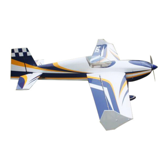
- Page 1 GOLDWING RC 74in SLICK540 30CC & 120E Giant Scale Aerobatic Aircraft...
-
Page 2: Specifications
Thank you for purchasing the new Goldwing RC giant scale aerobatic aircraft. This manual covers the SLICK540 30CC and 120E aircraft. Goldwing RC proudly presents 74in SLICK 30CC & 120E , Extreme Series, which is a premium product line of electric & gas RC airplanes designed for unlimited 3D performance. The new 74in SLICK adopts cutting edge aerodynamic features, such as streamlined canopy, aileron counterbalance, removable side force generators (SFGs) .The 74in SLICK is also loaded with high-end accessories including CF... -
Page 3: Included Features
Goldwing RC WARRANTY AND RETURN POLICY GoldWing RC guarantees this product to be free from defects in both material and workmanship at the date of purchase. This does not cover any parts damaged by use, misuse or modification. In no case shall liability exceed the original cost of this kit. - Page 4 Removable stab & rudder...
- Page 5 New 410cc KUZA Fuel Tank Assembly with aluminum tank cap for 30CC version...
- Page 6 Including anodized alloy fuel dot & fuel vent line plug for 30CC version Aluminium Backplate Hollowed-out Electric Spinner included for 120E version (Excellent cooling effect for brushless motor)
- Page 7 Including POM & ALU motor washers for 120E version Canopy hatch pins are made of nylon rods for better resistance aganist vibration One piece air foiled carbon fiber landing gear...
- Page 8 Items required to complete this model: 26-38 cc gas engine with stock or aftermarket Switches with charging jacks for the Rx exhaust system Rx batteries of significant capacity to power Appropriate propeller for your engine your choice of servos. ...
- Page 9 temperatures. Be sure to use a soft cover over your iron so you do not scratch the covering surface. Be sure you go over all seams and edges of the covering to assure it is secure to the airframe and other covering.
- Page 10 KUZA 3” Aluminium Backplate Hollowed-out Electric Spinner for 120E version KUZA new 410cc fuel Tank Assembly for 30CC version (including Aluminum fuel cap) KUZA anodized alloy fuel dot & fuel vent line plug for 30CC version...
- Page 11 Push rod kits: Two 2.5x60mm Pushrods for aileron. Two 2.5x130mm Pushrods for elevator.One 2.5x110mm for rudder(Pull-push style) Ball link assembly : 8 for ailerons & elevator & rudder. Servo lead safety clips:5 pcs...
- Page 12 Main wheels:2pcs (GW version are Alu wheels,and ARF version are nylon wheels) New axle kits Carbon fibre tail wheel assembly : GW version is U stents with CNC machined,and ARF version is common Carbon fibre tail wheel assembly. GW version ARF version...
- Page 13 4 allen key wrench Side force generators (mounted with four M3X18 hand bolts and 2 balsa sheets) Screews for landing gear: 4(4x20mm) hexagon bolts and 4 washers...
- Page 14 Bolts & washers for cowl: 4(3x14mm) Hexagon bolts and 2(10mm) PTFE washers and 2 wsahers 20 POM & ALU washers for 120E motor Gas engine washers for 30CC version: 12(20mm) POM washers...
-
Page 15: Rudder Assembly
RUDDER ASSEMBLY NOTE: There are pictures of different planes in this manual, however, this plane’s rudder is assembled the same way. 1.It is much easier to install the twin control horns before installing the rudder. Locate the carbon fiber rudder control horns, ball links, and associated bolts and nylon-insert lock nuts. Use some fine sandpaper to roughen up the center areas of the two control horns so that the glue adheres better. - Page 16 3. Apply 30 minute epoxy to hinges, then insert them into the hinge slots on the rudder, secure the rudder with masking tapes, then allow the epoxy to dry. 4. The SLICK can use either closed loop or a rear push pull servo for the rudder. We recommend that you balance the model assembled before choosing your servo placement.
- Page 17 8. The SLICK has the closed loop pre-installed and crimped at the rudder end. These can be connected with the M2.5 bolts and nut. The wire will be left looped inside the fuselage and will need to be connected to the servo arm.
- Page 18 the excess cable with wire cutters. Wick thin CA into the brass tube to help hold the cable secure. Repeat for the other cable. Hint: Once you have established the position of the threaded coupler on the cable, you can remove the ball link from the rudder horn to give you more working slack in the fuselage.
- Page 19 Cut off excess carbon fiber rudder horn, and use sandpaper to rough the parts needed to inlay, and use epoxy glue to glue the horn in place. Use 2.5X110mm push rod between the servo and the rudder horn. We recommend using KUZA 1.5” aluminium CNC servo arm (sold separately) for rudder control.
-
Page 20: Landing Gear Assembly
LANDING GEAR ASSEMBLY NOTE: There are pictures of different planes in this manual, however, this plane’s landing gear is assembled the same way. 1. Locate the supplied main and tail wheel landing gear parts and sort them out on your workbench. 2. - Page 21 3. Bolt the main gear to the bottom of the fuselage using the supplied screws and stainless steel Self-locking nuts. Place the bolts in through the can tunnel opening with appropriate size spanner. Remember the gear will rake forward. Adjust the position of the landing gear fairings, the secure with glue (shoe goo type).
- Page 22 5.Loosen out the inner nut, then apply thread lock to the axle. Tighten the nut back in place, allow the thread locker to dry.
- Page 23 6. Install the main wheel axles to the composite landing gear and tighten the nylon-insert lock nut. Install one wheel collar onto the axle. Use a second wheel collar as a guide to leave a gap on the inboard of the axle. Use a small drop of thread-lock and tighten in place.
- Page 24 GW version Tail wheel kit Installation 1. GW version tail wheel kit is almost pre-assembled in factory, for safety, please remove all screws and then re-assemble with thread locker. 2. Line up the caron fiber assembly onto the body of the aircrtaft and use the holes as a drill guide. Use a 2mm drill bit as a pilot hole, then apply thin CA to harden the wood.
- Page 25 3. Drill a 7mm hole on the bottom of rudder, 85-95mm away for the hinge line. Fill the hole and ball link with 30 minute epoxy. 4. The following is a picture of correctly installed tail wheel assembly. ARF version Tail wheel kit Installation...
- Page 26 1. Begin the tail wheel assembly by installing the hollow hex bolt and lock nut into the large hole at the rear of the tail wheel bracket. 2.Slide 3 wheel collars and the wheel onto the pre-bent tail wheel wire and tighten in place with thread lock as shown below.
- Page 27 3.Install steering rod, again, the use of thread-lock on any metal to metal screw is advised. 4.Line up the caron fiber assembly onto the body of the aircrtaft and use the holes as a drill guide. Use a 2mm drill bit as a pilot hole, then apply thin CA to harden the wood. Use the three self tapping screws and secure the assembly into place.
-
Page 28: Wings Assembly
WINGS ASSEMBLY NOTE: There are pictures of different planes in this manual, however, this plane’s wings is assembled the same way. 1. Aileron push rod linkage set. 2. The aileron control surfaces is Pre-hingeds for GW version. For ARF version, glue the hinge for the elevator. - Page 29 Locate the slots for the aileron control horn and remove the covering with a sharp knife. Place the horns into position and the cover over the top to work out the area needing to be removed. 3.Rough the area of the horn that will be glued in place. 4.Using 30 minute epoxy glue the horn and plate into the aileron.
- Page 30 5.Screw holes for servo mounting are pre-drilled by laser in factory, install servo with 4 self threading screws.Fit a metal servo arm centering with your radio. 6.Locate the included aluminum long servo arm, enlarge control holes with 2.5mm drill bit 7.Using the pushrods connect the servo arm to the horn.
-
Page 31: Elevator Assembly
Use M2.5 screws and nuts to connect the pushrod. Set it so the aileron it level when the arm is at 90 degrees. REPEAT FOR THE OTHER SIDE 8. We recommend using KUZA 1.5” aluminium CNC servo arm (sold separately) for wing control. ELEVATOR ASSEMBLY NOTE: There are pictures of different planes in this manual, however, this plane’s elevator is assembled the same way. - Page 32 2. Find the slots for the control arms in the elevators and remove the covering where the horns are inserted and the area for the plate. 3. Sand the area on the horn that will be glued inside the elevator. 4.
- Page 33 REPEAT FOR THE OTHER SIDE 5. Glue the hinge for the elevator. 6. Place long arms onto the servo’s you are planning to use for the elevators.
- Page 34 7. Fit the pushrod in place remembering one end is reverse threaded. Set it so the arm is centered and the elevator is flat. Choose the holes depending on how much deflection you require. 8. There is an option to use one servo or two servos for the elevator. If using one servo, the 2 parts of the elevator need to be connected by the fiberglass block with glue as shown below.
- Page 35 9. We recommend using KUZA 1.5” aluminium CNC servo arm (sold separately) for elevator control. For 30CC version,Engine, Exhaust, & Fuel System Installation Engine Installation NOTE: There are pictures of different planes in this manual, however, this plane’s engine is assembled the same way.
- Page 36 2. Fit the Cowl and measure the distance from the engine bulkhead to the front of the cowl, add approx 2- 3mm for the back plate and this is the length that your engine should be set. Using the correct length stand offs, mount your engine securely using bolts, washers, and locknuts.
- Page 37 4. Assemble the throttle servo mount using the supplied laser cut parts or there is a servo cutout in the bottom of the engine box for 28cc-38cc engines. Mount your throttle servo and complete your linkage setup. A hole will need to be drilled on the firewall to allow the pushrod to connect to the throttle arm on the carb. 6.
- Page 38 Installation of KUZA anodized alloy fuel dot & fuel vent line plug for 30CC version. 1. KUZA anodized alloy fuel dot & fuel vent line plug are included. 2. Installation of KUZA anodized alloy fuel dot Sites for KUZA fuel dot installation are pre-cut on both sides of the fuselage, you may install it on either side.
- Page 39 3. Installation of KUZA fuel vent line plug Similarly, two sites for vent line plug installation are available at the bottom of the fuselage. Use shape knife to remove the covering. Then put the nut. 120E Electric version Motor Installation 1.
- Page 40 3. Fix the battery with both Velcro and straps.
-
Page 41: Cowling Installation
COWLING INSTALLATION NOTE: There are pictures of different planes in this manual, however, this plane’s cowling is assembled the same way. 1. The cowl is secured with four 3 X 14mm bolts and washers.Apply nutlock onto the bolts as the vibration from the gas engine will shake them come loose. - Page 42 FINAL RADIO SYSTEM INSTALLATION Whether you use 72 MHz systems or the newer 2.4 GHz systems, correct radio installation and care is vital to the safe and reliable operation of your aircraft. Follow the manufacturer’s instruction for installation guidance of receivers and batteries paying attention to factors such as vibration isolation, adequate cooling, and clearances.
- Page 43 To perform properly without being too pitch sensitive, you must not go too aft on the CG. GoldWing RC recommends an initial CG setting of 107-126mm(4.2-5 inches) behind the leading edge of the wing at the root. More experienced pilots may want to set the CG further aft for more 3D capability.
- Page 44 Then install pull-pull ball links on control horns. Hook up the tail wheel spring. 3.Installation of stab Also the stab is removable for convenience in transportation, Attach elevators with 3x12mm Hex-head bolts and 10mm PTFE washers. Check these after every flight.
- Page 45 4. Install the wings onto the fuselage being careful to align the wing tube with the wings and not force it. The wing tube may be initially tight but will loosen after some with use. Guide your servo wires into the fuselage openings and connect to the correct aileron channels.
- Page 46 6. Fill your fuel tank making sure your vent line is not plugged or capped. With the canopy off, this is a good time to check for any fuel leaks. 7. Check all control surfaces for secure hinges by performed a slight tug on the control surfaces and observing if there is any give in the hinges.
- Page 47 KUZA Twisted 22 AWG Servo Extensions Two to three 12”(305mm) No. KAG002522 Two to three 18”(455mm) No. KAG002523 KUZA Gas Fuel line size: 6X3.5mm 3 color to choose: red , blue, yellow No. KAG006131R or KAG0061U or KAG0061Y...
- Page 48 * KUZA CNC Aluminum Fuel Dot 3 color to choose: black, blue, red No. KAG0231B or KAG0231U or KAG0231R * KUZA CNC Aluminum Fuel Vent Line Plug 3 color to choose: black, blue, red No. KAG0232B or KAG0232U or KAG0232R * KUZA Fuel line clips 10PCS No.
- Page 49 * KUZA 7075-T6 Alloy Servo Arm V2 * KUZA new Wingbag for 74in SLICK Two color to choose: red/ black, blue / silver No. KAG0093...
- Page 50 GOLDWING RC www.goldwingrc.com...
Need help?
Do you have a question about the SLICK540 30CC and is the answer not in the manual?
Questions and answers