Advertisement
Quick Links
Advertisement

Related Manuals for Goldwing RC 91in CORVUS 50-60CC


Summary of Contents for Goldwing RC 91in CORVUS 50-60CC
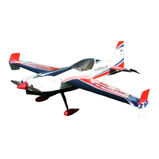
- Page 1 GoldWing RC 91in CORVUS 50-60CC Giant Scale Aerobatic Aircraft...
-
Page 2: Specifications
All contents copyright 2017, GoldWing RC Dear Customer, Thank you for purchasing the new Goldwing RC giant scale aerobatic aircraft. This manual covers the 91in CORVUS 50-60CC aircraft. Goldwing RC proudly presents 91n CORVUS, Extreme Series, which is a premium product line of electric &... - Page 3 Goldwing RC WARRANTY AND RETURN POLICY GoldWing RC guarantees this product to be free from defects in both material and workmanship at the date of purchase. This does not cover any parts damaged by use, misuse or modification. In no case shall liability exceed the original cost of this kit.
- Page 4 New extra strength Fiberglass control Horns kit Carbon fiber tail wheel assembly: GW version is CNC machined metal parts The CORVUS is designed to directly accommodate KUZA® rudder servo tray...
- Page 5 Including high quality Velcro Straps Including KUZA Socket Head Servo Screws Including KUZA 700cc Gas Tank V2 Version...
- Page 6 Including KUZA CNC Aluminum Fuel Dot & Fuel Vent Line Plug Including rubber grommets...
- Page 7 Including Gas engine mount kit Scheme A White /Yellow/black...
- Page 8 Scheme B Red/White /black...
- Page 9 Scheme C White/red /black...
- Page 10 Items required to complete this Model: 50-70 cc gas engine with stock or aftermarket Two heavy duty switches with charging jacks for the Rx exhaust systems Two high quality Rx batteries of significant Appropriate propeller for your engine capacity to power your choice of servos.
- Page 11 2. Be sure to seal any exposed wood with a thin coating of epoxy to prevent engine oil from soaking in. This is especially important around the engine compartment and servo openings with exposed areas. 3. Some modelers prefer to seal the hinge gaps using strips of appropriate covering or clear trim tape. We have found this to be helpful with models intended for higher speed flight or models with unusually large hinge gaps.
- Page 12 GW Version is including 3.5” Painted carbon fiber spinner .ARF Version is not included. KUZA new 700cc(24oz) larger volume fuel Tank (including Alloy fuel cap)
- Page 13 Adjustable pushrods kits: Four 3x61mm Pushrods for elevator & aileron. One 3x125mm Pushrod for rudder(Pull-push style) Pull-pull assembly kits for the rudder. Ball link assembly : 8 for ailerons and elevators.
- Page 14 Servo lead safety clips:6 pcs (Bag No. KAG0021) 3.5in Main wheels:2pcs GW version is Aluminium hub, ARF version is nylon hub New stainless steel Axle kits...
- Page 15 Carbon fibre tail wheel assembly:GW version is CNC machined metal parts Side force generators (4 x 3x12mm hex bolts & 4 x 3mm stainless steel self-locking nuts & 4 x washers) Bolts for landing gear: 4(4x20mm) hexagon bolts and 4(M4) stainless steel self-locking nuts & 4 washers...
- Page 16 Bolts & washers for cowl: 4(3x16mm) Hexagon bolts and 4(10mm) PTFE washers Bolts & washers for stab tails: 4(3x12mm) Hexagon bolts and 4(10mm) PTFE washers Gas engine mount kit...
-
Page 17: Rudder Assembly
RUDDER ASSEMBLY NOTE: There are pictures of different planes in this manual, however, this plane’s wings is assembled the same way. 1.It is much easier to install the twin control horns before installing the rudder. Locate the carbon fiber rudder control horns, ball links, and associated bolts and nylon-insert lock nuts. Use some fine sandpaper to roughen up the center areas of the two control horns so that the glue adheres better. - Page 18 3.To fit the rudder to the fin, locate the rudder hinge wire and insert. To make it easier to insert twist as it is inserted. 4. The CORVUS can use either closed loop or a rear push pull servo for the rudder. We recommend that you balance the model assembled before choosing your servo placement.
- Page 19 5. The CORVUS is supplied with a high quality set of pull-pull cables and ball-links. 6. Install your rudder servo into the precut locations in the fuselage. Using a fine drill pre-drill the holes and drop thin CA into the holes to strengthen the wood. You will need 3 inch arms on the servo. Set up your radio accordingly and center the rudder servo.
- Page 20 8. Use your radio system to center the rudder servo and attach either the supplied arm or an appropriate arm for your servo. Thread one of the ball links about half way onto one of the threaded couplers. Feed the loose end of one of the cables through a brass tube and then through the threaded coupler.
- Page 21 13. Use 3x125mm push rod between the servo and the rudder horn. Then use the wrench to adjust the pushrod to the appropriate length.
-
Page 22: Landing Gear Assembly
LANDING GEAR ASSEMBLY 1. Locate the supplied main and tail wheel landing gear parts and sort them out on your workbench. 2. 2. Bolt the main gear to the bottom of the fuselage using the supplied screws and stainless steel Self- locking nuts. - Page 23 4. Install the main wheel axles to the composite landing gear and tighten the nylon-insert lock nut. Install one wheel collar onto the axle. Use a second wheel collar as a guide to leave a gap on the inboard of the axle. Use a small drop of thread-lock and tighten in place.
- Page 24 6. Using silicone attaches the fairings to the fuselage. Use tape to hold them into position and leave for a few hours to ensure that the silicon has set. 7. Begin the tail wheel assembly by installing. Tail wheel assembly with CNC machined metal parts, including the aluminum tail wheel hub The installation is very simple, the factory has installed most of the accessories, please see the following pic ture.
-
Page 25: Wings Assembly
8. Use your finger to find the three holes at the bottom of the fuselage. Using a knife clear the holes and fix the tailwheel in place. Use loctite on the bolts. Drill a 6.5mm hole on the bottom of rudder, 85-100mm away for the hinge line. - Page 26 1. Aileron push rod linkage set. 3mmx61mm Pushrods for aileron. 2. Locate the slots for the aileron control horn and remove the covering with a sharp knife. Place the horns into position and the cover over the top to work out the area needing to be removed. 3.
- Page 27 REPEAT FOR THE OTHER SIDE 5. Place the servo in the bay and drill holes for the servo screws. Remove the servo and apply thin cyano to the holes. Refit the servo and screw in place. Fit a metal servo arm centering with your radio. 6.
-
Page 28: Elevator Assembly
Use M3 screws and nuts to connect the pushrod. Set it so the aileron it level when the arm is at 90 degrees. REPEAT FOR THE OTHER SIDE ELEVATOR ASSEMBLY 1. Push rod linkage set for elevator. 3mmx61mm Pushrods for elevator. 2. - Page 29 3. Sand the area on the horn that will be glued inside the elevator. 4. Using plenty of 30 minute epoxy fit the horn and plate into place. Use a ball joint and bolt to hold the horn in place while drying. REPEAT FOR THE OTHER SIDE 5.
- Page 30 7. Place the servo arm back onto the servo, remembering to centre. Use nutlock on the servo arm screw. 8. Fit the pushrod in place remembering one end is reverse threaded. Set it so the arm is centered and the elevator is flat. Choose the holes depending on how much deflection you require.
- Page 31 REPEAT FOR THE OTHER SIDE 9. We recommend using KUZA 1.75” aluminium CNC servo arm (sold separately) for elevator control. ENGINE, EXHAUST, & FUEL SYSTEM INSTALLATION Templates are provided in the kit for both DA 50 and 60 along with the 3W 55 cc. Select the correct guide for your engine and mark and drill the mounting holes and cut out the center as indicated.
- Page 32 2. Fit the Cowl and measure the distance from the engine bulkhead to the front of the cowl, add approx 2- 3mm for the spinner back plate and this is the length that your engine should be set Using the correct length stand offs, mount your engine securely using bolts, 20mm POM washers, and locknuts.
- Page 33 6. An extra servo can be fitted for choke or a mechanical linkage can be used. 7. The new KUZA 700cc Fuel Tank with aluminum tank cap is preassembled. Complete the installation in the fuselage using zip ties or velcro straps to hold the tank in position. Connect a fuel line between the tank and carb, a fuel line between the tank vent and the bottom of the fuselage, and a fill line to a fueling port which can be mounted on the fuselage side opposite your ignition switch.
- Page 34 A barb on the bottom of the fuselage can be fitted for the vent. 8. The CORVUS comes with a canister pipe tunnel. Standard muffler, pitts muffler, canister or tuned pipe can be fitted. If a tuned pipe is going to be used the end of the can tunnel can be removed. The tunnel can be closed off to accept canisters of all sizes, or stock mufflers.
- Page 35 Tuned Pipe Mounting The CORVUS comes with many openings for the exhaust outlet, line up the exhaust then remove the covering for the required outlet. They come with covers that can be used for cooling. Use a soldering iron to open up the holes.
- Page 36 Installation of KUZA Fuel Dot and Fuel Vent Line Plug (Included) 1. From June 2015 and on, all Goldwing gas airplanes are made ready for KUZA fuel dot and vent line plug. Available in three colors: black, red and blue. 2.
- Page 37 Secure the housing of fuel dot with supplied 2.5 mm self-tapping screws, then plug and install the fuel line to complete the setup of fuel dot. 3. Installation of KUZA CNC Aluminum Fuel Vent Line Plug...
-
Page 38: Cowling Installation
Similarly, two sites for vent line plug installation are available at the bottom of the fuselage. Secure KUZA vent line plug with four 2.5 mm self-tapping screws as shown below. COWLING INSTALLATION With the engine fitted, tape a piece of card to the bottom of the fuselage that can overlap the cylinder head. Remove the engine and refit the cowl. - Page 39 As the CORVUS has a scale inlet, depending on your engine it may need to be removed. If it is still attached it may be beneficial to strengthen with a small amount of glass cloth. If your exhaust outlet comes out within the cowl area then use the same method. ...
- Page 40 3.The cowl is secured with four 3 x 16mm bolts and washers. Apply nutlock onto the bolts as the vibration from the gas engine will shake them come loose. Labels are provided for aligning the drill holes for the cowl. Stick then on without the cowl, mark the hole. Fit the cowl then press back down.
- Page 41 To perform properly without being too pitch sensitive, you must not go too aft on the CG. GoldWing RC recommends an initial CG setting of 136-158mm(5.4-6.2 inches) behind the leading edge of the wing at the root. More experienced pilots may want to set the CG further aft for more 3D capability.
- Page 42 Note: The best way to check your balance is to trim for level flight at about 1/2 to 3/4 throttle and then roll inverted. The aircraft should maintain level flight with very little to no down elevator input. If the aircraft climbs when inverted then you’ve probably got your CG too far aft.
- Page 43 3.Install the wings onto the fuselage being careful to align the wing tube with the wings and not force it. The wing tube may be initially tight but will loosen after some with use. Guide your servo wires into the fuselage openings and connect to the correct aileron channels.
- Page 44 5. Fill your fuel tank making sure your vent line is not plugged or capped. With the canopy off, this is a good time to check for any fuel leaks. 6. Position the canopy in place and tighten Canopy Bolts. Be sure to use the supplied PTFE washers under the screw heads.
- Page 45 7. Check all control surfaces for secure hinges by performed a slight tug on the control surfaces and observing if there is any give in the hinges. Check all control rods, ball links, servo screws, etc. for correct operation and installation.
- Page 46 KUZA Gas Fuel line size: 6X3.5mm 3 color to choose: red , blue, yellow No. KAG006131R or KAG0061U or KAG0061Y * KUZA Fuel line clips 10PCS No. KAG02454...
- Page 47 * KUZA 7075-T6 Alloy Servo Arm V2...
- Page 48 * KUZA new Wingbag for 60CC Two color to choose: red/ black, blue / silver No. KAG0093 GoldWing RC www.goldwingrc.com...
Need help?
Do you have a question about the 91in CORVUS 50-60CC and is the answer not in the manual?
Questions and answers