
Related Manuals for Goldwing RC SU26M 50CC V4


Summary of Contents for Goldwing RC SU26M 50CC V4
- Page 1 GoldWing RC SU26M 50CC V4 Giant Scale Aerobatic Aircraft All contents copyright 2015, GoldWing RC Version 4.0, June 2015...
-
Page 2: Specifications
Thank you for purchasing the new Goldwing RC giant scale aerobatic aircraft. This manual covers the SU26M 50CC V4 aircraft. The SU26M is designed for the popular 50-60 cc engines and weighs approximately 7.5 kg to 8.1 kg. Perfect for IMAC or Freestyle flying, this new giant offers... - Page 3 Goldwing RC WARRANTY AND RETURN POLICY GoldWing RC guarantees this product to be free from defects in both material and workmanship at the date of purchase. This does not cover any parts damaged by use, misuse or modification. In no case shall liability exceed the original cost of this kit.
- Page 4 Larger aileron and elevator design. Up to 60 degrees of throw on all control surfaces for excellent 3D aerobatic flying High quality ball link assemblies Aluminium hub rubber wheels All contents copyright 2015, GoldWing RC Version 4.0, June 2015...
- Page 5 Improved axles (the material of the axle is now stainless steel ) Servo lead safety clips High performance cap head bolts All contents copyright 2015, GoldWing RC Version 4.0, June 2015...
- Page 6 Flat nylon hinges for inproved flying strength Honeycomb board carton packing for safer transportation Pre-hinged control surfaces All contents copyright 2015, GoldWing RC Version 4.0, June 2015...
- Page 7 Installed servo wire guide tube Extra covering provided for small repairs, genuine Ultracote / Oracover Removable rudder Side force generators All contents copyright 2015, GoldWing RC Version 4.0, June 2015...
- Page 8 CNC anodized aluminum canopy bolts Full length tuned pipe design inside the fuselage Carbon Fiber accessories version: Extra strength carbon fiber control horns All contents copyright 2015, GoldWing RC Version 4.0, June 2015...
- Page 9 One piece air foiled carbon fiber landing gear Carbon fiber tail wheel assembly with CNC machined metal parts, including the aluminium tail wheel hub. All contents copyright 2015, GoldWing RC Version 4.0, June 2015...
- Page 10 Increased diameter carbon fiber wing tube over previous versions Carbon fiber stab tube All contents copyright 2015, GoldWing RC Version 4.0, June 2015...
- Page 11 New wheel pants design The SU26M is designed to directly accommodate KUZA® rudder servo tray New KUZA Fuel Tank Assembly with aluminum tank cap All contents copyright 2015, GoldWing RC Version 4.0, June 2015...
- Page 12 Scheme B : Red /white/ black All contents copyright 2015, GoldWing RC Version 4.0, June 2015...
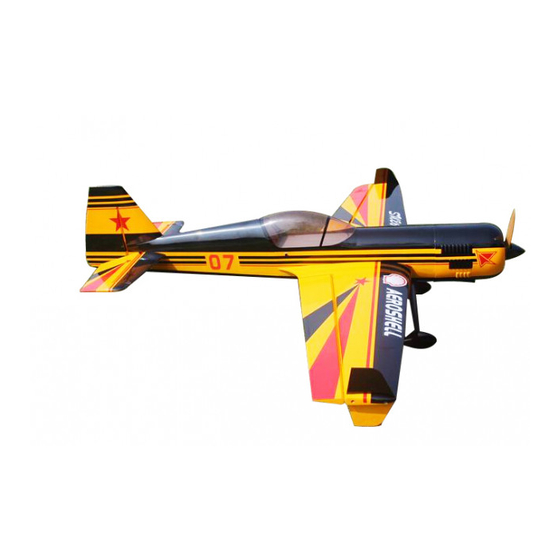
- Page 13 Scheme C Yellow/red/black All contents copyright 2015, GoldWing RC Version 4.0, June 2015...
- Page 14 One receiver of your choice One quality throttle servo and appropriate Required Tools servo arm Covering Iron and heat gun Four high quality metal gear servos of 180 All contents copyright 2015, GoldWing RC Version 4.0, June 2015...
- Page 15 Sealing the hinge gaps is therefore left as an option for the modeler. Please verify the accessories before commencing assembly: Carbon Fiber control Horns (Bag No. KA06CA) : 8 single horns for ailerons and elevator. 2 dual horns for rudder. All contents copyright 2015, GoldWing RC Version 4.0, June 2015...
- Page 16 Sand the area of the horn that will be glued to help adhesion. Adjustable pushrods kits: (Bag No. KA05CBG2) Four 3x61mm pushrods for ailerons. One 3x125mm pushrods rudder(Pull-push style) All contents copyright 2015, GoldWing RC Version 4.0, June 2015...
- Page 17 Ball link assembly (Bag No. KAG00131): 8 for ailerons and elevators. Alu long arm kits (Bag No. KA05CC): 4 single arms for ailerons and elevators. 1 dual arm for the rudder. All contents copyright 2015, GoldWing RC Version 4.0, June 2015...
- Page 18 Carbon fibre tail wheel assembly with CNC machined metal parts, including the aluminium tail wheel hub. (Bag No. KAGC104) 4mm ALU canopy bolts & 12mm PTFE washers (Bag No.KAG0043) All contents copyright 2015, GoldWing RC Version 4.0, June 2015...
- Page 19 Side force generators (4 x 3x16mm hex bolts & 4 x washers) Bolts for landing gear: 4(4x20mm) hex bolts and 4(M4) stainless steel self-locking nuts & 4 washers All contents copyright 2015, GoldWing RC Version 4.0, June 2015...
- Page 20 Bolts & washers for stab tails: 4(3x12mm) Hexagon bolts and 4(10mm) PTFE washers Washers for gas engine: 12(20mm) POM washers Spares bag(Two spare aluminum hand-twist bolts \Two spare wing bolts\One spare tail wheel spring) All contents copyright 2015, GoldWing RC Version 4.0, June 2015...
-
Page 21: Rudder Assembly
Set aside until cured. NOTE: There are pictures of different planes in this manual; however, this plane’s rudder is assembled the same way. All contents copyright 2015, GoldWing RC Version 4.0, June 2015... - Page 22 CA into the holes to strengthen the wood. You will need 3 inch arms on the servo. Set up your radio accordingly and center the rudder servo. 7.Aluminum dual servo arm are include in the kit, enlarge the control holes with 3mm drill bit. All contents copyright 2015, GoldWing RC Version 4.0, June 2015...
- Page 23 Re-install the ball link prior to setting the other cable. All contents copyright 2015, GoldWing RC Version 4.0, June 2015...
- Page 24 12 . We recommend using KUZA® rudder servo tray (available separately) for better rudder performance. 13.This SU26M 50cc is designed to directly accommodate KUZA® rudder servo tray, and so will be all other pending Goldwing airplanes that are 50cc or greater. All contents copyright 2015, GoldWing RC Version 4.0, June 2015...
- Page 25 14.You will need to provide 3X42 mm push rods (2 Pcs) and ball links (4 Pcs), depending on the servo of your choice, a KUZA 3.25” aluminum CNC servo arm may also be needed. 15. Assembling rudder servo tray. All contents copyright 2015, GoldWing RC Version 4.0, June 2015...
- Page 26 16.The SU26M also provides pull-push style for rudder. Below is picture of pull-push style linkage set. Cut off excess carbon fiber rudder horn, and use sandpaper to rough the parts needed to inlay, and use epoxy glue to glue the horn in place. All contents copyright 2015, GoldWing RC Version 4.0, June 2015...
- Page 27 18. Use 3x125mm push rod between the servo and the rudder horn. Then use the wrench to adjust the pushrod to the appropriate length. All contents copyright 2015, GoldWing RC Version 4.0, June 2015...
-
Page 28: Landing Gear Assembly
Remember the gear will rake forward. 3. Loosen out the inner nut, then apply thread lock to the axle. Tighten the nut back in place, allow the thread locker to dry. All contents copyright 2015, GoldWing RC Version 4.0, June 2015... - Page 29 For greater strength, filing a flat where the grub screw mounts will stop the collet being able to be turned. All contents copyright 2015, GoldWing RC Version 4.0, June 2015...
- Page 30 Use loctite on the bolts. Then install the spring, using the self-tapping screw to attach the other end of the spring onto the rudder. All contents copyright 2015, GoldWing RC Version 4.0, June 2015...
-
Page 31: Wings Assembly
7. The following is a picture of correctly installed tail wheel assembly. NOTE: One spare tail wheel spring is included in the spare hardware pack. WINGS ASSEMBLY 1. Aileron push rod linkage set. 3mmx61mm Pushrods for aileron. All contents copyright 2015, GoldWing RC Version 4.0, June 2015... - Page 32 Place the horns into position and the cover over the top to work out the area needing to be removed. 3. Rough the area of the horn that will be glued in place. All contents copyright 2015, GoldWing RC Version 4.0, June 2015...
- Page 33 4. Using 30 minute epoxy glue the horn and plate into the aileron. REPEAT FOR THE OTHER SIDE All contents copyright 2015, GoldWing RC Version 4.0, June 2015...
- Page 34 5. A string is pre-placed in the wing to facilitate the installation of aileron servo wire. 6. Connect extension servo wire, secure with safe clips. 7. Tie up servo extension with the string, and then pull it through the wing. All contents copyright 2015, GoldWing RC Version 4.0, June 2015...
- Page 35 9. Locate the included aluminum long servo arm, enlarge control holes with 3mm drill bit 10.Using the pushrods connect the servo arm to the horn. Remember that on the pushrod one end is reverse threaded. All contents copyright 2015, GoldWing RC Version 4.0, June 2015...
-
Page 36: Elevator Assembly
1. Push rod linkage set for elevator. 3mmx61mm Pushrods for elevator. 2. Find the slots for the control arms in the elevators and remove the covering where the horns are inserted and the area for the plate. All contents copyright 2015, GoldWing RC Version 4.0, June 2015... - Page 37 4. Using plenty of 30 minute epoxy fit the horn and plate into place. Use a ball joint and bolt to hold the horn in place while drying. REPEAT FOR THE OTHER SIDE 5. Place long arms onto the servo’s you are planning to use for the elevators. All contents copyright 2015, GoldWing RC Version 4.0, June 2015...
- Page 38 8. Fit the pushrod in place remembering one end is reverse threaded. Set it so the arm is centered and the elevator is flat. Choose the holes depending on how much deflection you require. All contents copyright 2015, GoldWing RC Version 4.0, June 2015...
- Page 39 Notice that the engine center line is offset to the left to compensate for the right thrust built into the engine box. All contents copyright 2015, GoldWing RC Version 4.0, June 2015...
- Page 40 Secure the pickup lead and ignition wires with zip ties so that they do not vibrate or touch any hot part of the engine or exhaust. All contents copyright 2015, GoldWing RC Version 4.0, June 2015...
- Page 41 All contents copyright 2015, GoldWing RC Version 4.0, June 2015...
- Page 42 Trial fit your exhaust system now and work out any additional supports, but do not permanently install the system until you fit the cowling in the next steps. Pitts Muffler All contents copyright 2015, GoldWing RC Version 4.0, June 2015...
- Page 43 Canister Fitting All contents copyright 2015, GoldWing RC Version 4.0, June 2015...
- Page 44 2. Installation of KUZA CNC Aluminum Fuel Dot Sites for KUZA fuel dot installation are pre-cut on both sides of the fuselage, you may install it on either side. Use shape knife to remove the covering. All contents copyright 2015, GoldWing RC Version 4.0, June 2015...
- Page 45 Secure the housing of fuel dot with supplied 2.5 mm self-tapping screws, then plug and install the fuel line to complete the setup of fuel dot. All contents copyright 2015, GoldWing RC Version 4.0, June 2015...
-
Page 46: Cowling Installation
With the engine fitted, tape a piece of card to the bottom of the fuselage that can overlap the cylinder head. Remove the engine and refit the cowl. Then fold over the card to show where the cylinder head would be as below. All contents copyright 2015, GoldWing RC Version 4.0, June 2015... - Page 47 Use a dremel tool to remove the material. When the cowl clears the engine etc correctly the prop shaft of the engine will be in the centre of the cowl. All contents copyright 2015, GoldWing RC Version 4.0, June 2015...
- Page 48 Labels are provided for aligning the drill holes for the cowl. Stick then on without the cowl, mark the hole. Fit the cowl then press back down. The hole will then show the area to drill. Sere below. All contents copyright 2015, GoldWing RC Version 4.0, June 2015...
- Page 49 5. Check all radio programming and control surface operations thoroughly before your initial flight. Check your radio range according to the radio manufacturer’s instructions both with the engine off and running. All contents copyright 2015, GoldWing RC Version 4.0, June 2015...
- Page 50 To perform properly without being too pitch sensitive, you must not go too aft on the CG. GoldWing RC recommends an initial CG setting of 130-152mm (5.1-6.0 inches) behind the leading edge of the wing at the root. More experienced pilots may want to set the CG further aft for more 3D capability.
- Page 51 The rudder is removable for convenience in transportation, it is connected to fuselage by inserting a 1.8 mm steel rod through the hinge line. Then install pull-pull ball links on control horns. Hook up the tail wheel spring. All contents copyright 2015, GoldWing RC Version 4.0, June 2015...
- Page 52 Servo clips are highly recommended. Once you have the wings fully seated in the fuselage tighten the wing bolts inside the fuselage. All contents copyright 2015, GoldWing RC Version 4.0, June 2015...
- Page 53 7. Position the canopy in place and tighten ALU Canopy Bolts. Be sure to use the supplied PTFE washers under the screw heads. All contents copyright 2015, GoldWing RC Version 4.0, June 2015...
- Page 54 Recommend Accessories(Not included): * KUZA Gas Fuel line size: 6X3.5mm 3 color to choose: red , blue, yellow No. KAG006131R or KAG0061U or KAG0061Y All contents copyright 2015, GoldWing RC Version 4.0, June 2015...
- Page 55 * KUZA CNC Aluminum Fuel Dot 3 color to choose: black, blue, red No. KAG0231B or KAG0231U or KAG0231R * KUZA CNC Aluminum Fuel Vent Line Plug 3 color to choose: black, blue, red No. KAG0232B or KAG0232U or KAG0232R All contents copyright 2015, GoldWing RC Version 4.0, June 2015...
- Page 56 * KUZA Fuel line clips 10PCS No. KAG02454 * KUZA 1x servo tray No. KAG0T01 All contents copyright 2015, GoldWing RC Version 4.0, June 2015...
- Page 57 47mm/1.75in Single No. KAG0S7F 100mm/4in Dual No. KAG0D723F For Hitec servo(24T): 47mm/1.75in Single No. KAG0S7H 100mm/4in Dual No. KAG0D73H For JR servo(23T): 47mm/1.75in Single No. KAG0S73J 100mm/4in Dual No. KAG0D73J All contents copyright 2015, GoldWing RC Version 4.0, June 2015...
- Page 58 * KUZA new Wingbag for 50CC Two color to choose: red/ black, blue / silver No. KAG0093 3.5in C.F spinner (Not Included) All contents copyright 2015, GoldWing RC Version 4.0, June 2015...
- Page 59 All contents copyright 2015, GoldWing RC Version 4.0, June 2015...
Need help?
Do you have a question about the SU26M 50CC V4 and is the answer not in the manual?
Questions and answers