
Related Manuals for Goldwing RC Electric Extreme YAK55M 70E


Summary of Contents for Goldwing RC Electric Extreme YAK55M 70E
- Page 1 GOLDWING RC 60in YAK55M 70E Electric Extreme Series All contents copyright 2015, GOLDWING RC Version 1.0, Aug 2015...
- Page 2 Propellers: 500kv 15X8, 450KV 16X8 Dear Customer, Thank you for purchasing the new GoldWing RC Electric Extreme series aircraft. This manual covers the 60in YAK55M 70E aircraft. Goldwing RC has long-term partnership with EG Aircraft (USA) in manufacturing 3D aerobatic model airplanes. It is a premium product line of electric RC airplanes designed for unlimited 3D performance.
- Page 3 GOLDWING RC WARRANTY AND RETURN POLICY GoldWing RC guarantees this product to be free from defects in both material and workmanship at the date of purchase. This does not cover any parts damaged by use, misuse or modification.
- Page 4 Larger aileron and elevator design. Up to 60 degrees of throw on all control surfaces for excellent 3D aerobatic flying Pre-hinged Control Surfaces High quality ball link assemblys Extension Lead Safety Clips High Density light Rubber Wheels All contents copyright 2015, GOLDWING RC Version 1.0, Aug 2015...
- Page 5 Improved new Axle (the material of Axle is stainless steel ) High performance cap head screws All contents copyright 2015, GOLDWING RC Version 1.0, Aug 2015...
- Page 6 Extra covering provided for small repairs and Covered in Genuine Ultracote / Oracover The air exit for the electric set up still needs to be inside the fuselage behind the rudder tray. All contents copyright 2015, GOLDWING RC Version 1.0, Aug 2015...
- Page 7 Side Force Generators KUZA Alloy Backplate Hollowed-out Electric Spinner included All contents copyright 2015, GOLDWING RC Version 1.0, Aug 2015...
- Page 8 Quick release canopy latch Carbon Fiber accessories version: Extra strength Carbon Fiber control Horns One piece air foiled carbon fiber landing gear All contents copyright 2015, GOLDWING RC Version 1.0, Aug 2015...
- Page 9 Light Electric C.F.Tail wheel assembly Strengthened fuselage by carbon fiber board and rods Larger carbon fiber wing tube diameter. All contents copyright 2015, GOLDWING RC Version 1.0, Aug 2015...
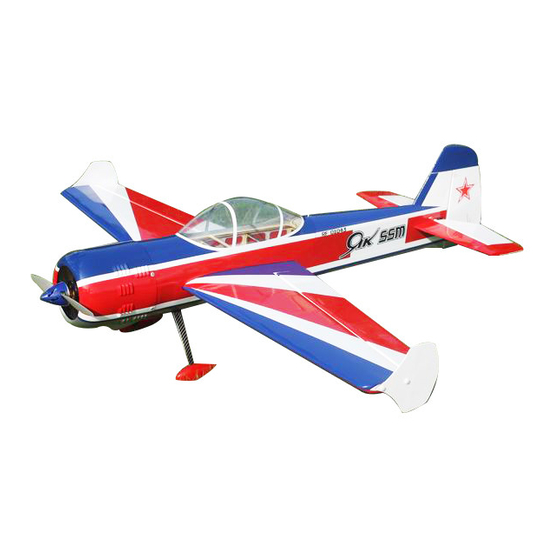
- Page 10 Scheme A White/red/blue Scheme B Yellow/ black/red All contents copyright 2015, GOLDWING RC Version 1.0, Aug 2015...
- Page 11 Receiver of your choice (minimum 4 channels) RC radio of your choice Shop Supplies/Tools Covering Iron and heat gun Hobby tools such as screwdrivers, hobby knife, drill and drill bits, piers, etc. All contents copyright 2015, GOLDWING RC Version 1.0, Aug 2015...
- Page 12 Aircrafts that utilize a very tight double beveled hinge line and do not normally require this step. Sealing the hinge gaps is therefore left as an option for modellers. All contents copyright 2015, GOLDWING RC Version 1.0, Aug 2015...
- Page 13 Please verify the accessories before assemble: Carbon Fiber control Horns (Bag No. KA07NA2A): 2 horns for ailerons, 1 for elevator, and 1 for rudder. 2.5"(63mm) CNC Alloy Backplate Hollowed-out Spinner (Bag No. KAG0203) All contents copyright 2015, GOLDWING RC Version 1.0, Aug 2015...
- Page 14 Light Electric C.F.Tail wheel assembly (Bag No. KAG0101) Pushrods kits: Three 2x65mm pushrods for ailerons & elevator. One 2x85mm pushrods for rudder. Ball link assembly (Bag No. KAG0011): 8 PCS All contents copyright 2015, GOLDWING RC Version 1.0, Aug 2015...
- Page 15 Servo lead safety clips (Bag No. KAG0019):4 pcs 2.25” main wheels(Bag No. KAG0146):2pcs New stainless steel Axle kits (Bag No. KA07NH) Extra covering provided for small repairs All contents copyright 2015, GOLDWING RC Version 1.0, Aug 2015...
- Page 16 3 Hex keys (Bag No. KA07NE) Side force generators (mounted with four M3X18 hand bolts and 2 wood sheets) 4 (3x16mm) hex-head bolts & Washers for landing gear mounting All contents copyright 2015, GOLDWING RC Version 1.0, Aug 2015...
- Page 17 Screews & Washers for cowl: 4(2.5x12mm) Hexagon socket screws & 4 PTFE Washers Motor mounting hardware set Spares bag(Two spare wing bolts \One spare tail wheel \One spare tail wheel spring) All contents copyright 2015, GOLDWING RC Version 1.0, Aug 2015...
-
Page 18: Rudder Assembly
Insert control horn into base plate then into the slot, trace the edge of base plate with hobby knife then remove the underlying covering. All contents copyright 2015, GOLDWING RC Version 1.0, Aug 2015... - Page 19 Wipe off excessive epoxy with alcohol wipes. Set aside until cured. 1.5 Use epoxy glue to connect nylon hinges for rudder. All contents copyright 2015, GOLDWING RC Version 1.0, Aug 2015...
- Page 20 Once satisfied, permanently attach the ball links to the servo arms and horns with the supplied screw and nut. We recommend using KUZA 1.25” aluminium CNC servo arm (sold separately) for rudder control. All contents copyright 2015, GOLDWING RC Version 1.0, Aug 2015...
-
Page 21: Landing Gear Installation
Landing Gear Installation 2.1 Locate the landing gear set 2.2 Bolt the main gear to the bottom of the fuselage using the supplied bolts All contents copyright 2015, GOLDWING RC Version 1.0, Aug 2015... - Page 22 Use a small drop of thread-lock and tighten in place. Slide the wheel onto the axle and install a second wheel collar also using thread-lock on the set screw. All contents copyright 2015, GOLDWING RC Version 1.0, Aug 2015...
- Page 23 Repeat the above steps for the other main gear. 2.5 Tail wheel assembly for electric airplanes. 2.6 Tail wheel kit is pre-assembled in factory, for safety, please remove all screws and then re- assemble with thread locker. All contents copyright 2015, GOLDWING RC Version 1.0, Aug 2015...
- Page 24 For best results, the pivot point of the assembly should be over the hinge line of the rudder. 2.8 Drill a hole on the bottom of rudder, 70-100mm away for the hinge line. Secure the tail wheel spring with provided self-threading screw. All contents copyright 2015, GOLDWING RC Version 1.0, Aug 2015...
-
Page 25: Wing Assembly
Insert control horn into base plate then into the slot, trace the edge of base plate with hobby knife then remove the underlying covering. All contents copyright 2015, GOLDWING RC Version 1.0, Aug 2015... - Page 26 KUZA 1” aluminium CNC servo arm is recommended for aileron control (sold separately). The servo arm should be as close to perpendicular to the control rod All contents copyright 2015, GOLDWING RC Version 1.0, Aug 2015...
- Page 27 1.4 to install control horns for elevators. Elevator horn slot is located on the left side of elevator. Remove covering over the hole for horizontal stabilizer on fuselage. Removing covering on the central part of horizontal All contents copyright 2015, GOLDWING RC Version 1.0, Aug 2015...
- Page 28 Insert the horizontal stabilizer into fuselage, make sure it’s centered. Apply thin and gap-filling medium CA to glue it in place. Glue the nylon hinges for the elevator with epoxy glue. All contents copyright 2015, GOLDWING RC Version 1.0, Aug 2015...
- Page 29 Locate the slots for elevator servo, remove covering. Connect wire extension to your servos before feeding the wire into fuselage. Install servo with screws supplied by servo manufacturer. All contents copyright 2015, GOLDWING RC Version 1.0, Aug 2015...
-
Page 30: Motor Mounting
Motor Mounting 5.1 Find the hardware set for motor installation in the hardware package. 5.2 Blind nuts are pre-installed behind the firewall. All contents copyright 2015, GOLDWING RC Version 1.0, Aug 2015... -
Page 31: Cowl Installation
6 Cowl Installation 6.1 Test fit the cowl first, make sure it fits well with canopy and fuselage. 6.2 There are pre-drilled screw holes on the cowl and the fuselage. All contents copyright 2015, GOLDWING RC Version 1.0, Aug 2015... - Page 32 7.2 The fuselage ply sides provide space to mount your switches just below the canopy. Mount your switches according to the manufacturer’s instructions and route your wires safely and securely as above. All contents copyright 2015, GOLDWING RC Version 1.0, Aug 2015...
- Page 33 If the nose drops more than slightly, then you are most likely nose heavy. Recommended control surface deflections: Low Rate High Rate Elevator 15 degrees 45-55 degrees Rudder 25 degrees 40-50 degrees Ailerons 25 degrees 40-50 degrees All contents copyright 2015, GOLDWING RC Version 1.0, Aug 2015...
- Page 34 9.3 Cut the wing film needed to be install the SFG. Fixed the SFG Use M3X18 hand bolts and wood sheets. Installation of the SFG is optional. All contents copyright 2015, GOLDWING RC Version 1.0, Aug 2015...
- Page 35 9.6 Check your batteries and perform a proper range check once again with the engine off and running. Be sure all surfaces are moving in the correct direction and the proper amount for your flying setup. All contents copyright 2015, GOLDWING RC Version 1.0, Aug 2015...
- Page 36 Accessories *KUZA Heavy duty aluminum Servo Arm (Not included) FUTABA servo arms HITEC servo arms JR servo arms 26mm/1in for aileron No. KAG0S70F/KAG0S70H/KAG0S70J All contents copyright 2015, GOLDWING RC Version 1.0, Aug 2015...
- Page 37 32mm/1.25in for elevator & rudder No. KAG0S71F/KAG0S71H/KAG0S71J * KUZA new Wingbag for 70E Two color to choose: orange/ silver, blue / silver No. KAG0091 All contents copyright 2015, GOLDWING RC Version 1.0, Aug 2015...
- Page 38 All contents copyright 2015, GOLDWING RC Version 1.0, Aug 2015...
Need help?
Do you have a question about the Electric Extreme YAK55M 70E and is the answer not in the manual?
Questions and answers