Advertisement
Quick Links
Advertisement

Related Manuals for Goldwing RC 91in EXTRA300LP50-60CC


Summary of Contents for Goldwing RC 91in EXTRA300LP50-60CC
- Page 1 ARF MODEL 91in EXTRA300LP 50-60CC Instruction Manual...
-
Page 2: Specifications
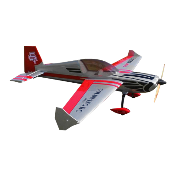
Dear Customer, Thanks for purchasing this newly designed 91in EXTRA300 50-60CC aerobatic RC airplane. The weight is approximately 17.5Lbs. It’s good for IMAC and free style flying. It’s a beautiful plane with amazing flight performance. It’s covered with genuine monocote, and comes with good quality accessories, including carbon fiber wing tube, Anodized 6061 aluminum landing gear or carbon fiber as an option. -
Page 3: Features Included
RADIO:6+CH/5-6S FEATURES INCLUDED Newly designed structure Two pieces removable wings & stabs Larger aileron and elevator design for excellent 3D aerobatic flying Full length Tuned pipe tunnel designed into fuselage Servo extension safety connector clips High performance cap head bolts Flat nylon hinges for increased strength High quality 3mm ball links assembly Carbon fiber wing tube... - Page 4 Adjustable pushrods for easy fine tuning(Includes wrench) New dual fiberglass horn assembly...
- Page 5 Carbon fiber tail wheel assembly High-quality durable rubber wheels Stainless steel Axles Two options for landing gear: Anodized 6061 Aluminum or Carbon fiber Carbon fiber landing gear Anodized 6061 Aluminum landing gear...
- Page 6 X basla batten structure ensures high strength of fuselage Canopy hatch pins are made of nylon rods for better resistance aganist vibration The EXTRA is designed to directly accommodate KUZA® rudder servo tray. New KUZA Gas Tank with alloy tank cap...
- Page 7 Scheme A : Silvery/red/ black...
- Page 8 Scheme B : White/ blue/black Scheme C : White /red/blue...
- Page 9 Items Required to Complete This Model: Two switches with charging jacks for the Rx 50-70CC Gas engine and exhaust Two high quality Rx batteries of significant Appropriate propeller for your Motor capacity to power your choice of servos. ...
- Page 10 Note: As with all kits, it’s a good idea to read all the instructions and study the parts before you begin construction. Handle the parts of this kit with care so you do not damage any of the structure or covering. Inspect all the parts for any shipping damage and report any issues to as soon as you can.
- Page 11 There is a layer of protection film on the horns. Please remove the film as shown following picture. Make sure to sand the horns so the surface is rough to glue correctly. Pushrods(Bag No. KA05CBG2) Four 3x61mm pushrods for ailerons. One 3x125mm pushrods rudder (Pull-push style)...
- Page 12 Pull-pull assembly kits for the rudder. (Bag No. KA05CD) Ball link assemblies (Bag No. KAG00131): 8 for ailerons and elevators. Alu long arm kits (Bag No. KA05CC): 4 single arms for ailerons and elevators. 1 dual arm for the rudder. 6 Servo extension safety connector clips (Bag No.
- Page 13 Main rubber wheels (Bag No. KAG014B):2PCS New stainless steel Axle kits (Bag No. KA05CH): 2PCS New Carbon fiber tail wheel assembly. (Bag No. KAG0104)
- Page 14 4mm ALU canopy bolts & 12mm PTFE washers (Bag No.KAG0043) Side force generators (mounted with four M3X18 hand bolts and 2 balsa sheets) Bolts for landing gear: 4(4x20mm) hex bolts and 4(M4) stainless steel self-locking nuts & 4 washers Bolts & washers for cowl: 4(3x16mm) Hexagon bolts and 2(10mm) PTFE washers and 2 wsahers...
-
Page 15: Wing Assembly
4 allen keys(Bag No. KA05CE) Bolts & washers for stab tails: 4(3x12mm) Hexagon bolts and 4(10mm) PTFE washers Washers for gas engine: 12(20mm) POM washers Wing Assembly 1.Aileron push rod linkage set. 3x61mm Pushrods for aileron. - Page 16 2.It is much easier to install the twin control horns before installing the wing. Locate the fiberglass aileron control horns, ball links, and associated bolts and nylon-insert lock nuts. Use some fine sandpaper to roughen up the center areas of the two control horns so that the glue adheres better. Using a sharp hobby knife cut the covering away from the slots in the rudder and trial fit the two control horns.
- Page 17 9. Cut the covering from the aileron servo openings from corner to corner and iron down inside the openings. Connect servo wire extensions to your servos and secure the connections with the supplied clips, your own clips, or tape. Feed the servo wires into the wing and out the root. Install the servos and screw firmly in place.
-
Page 18: Elevator Assembly
Elevator Assembly 1. Push rod linkage set for elevator. 3x61mm Pushrods for elevator. 2. Find the slots for the control arms in the elevators and remove the covering where the horns are inserted and the area for the plate. 3. Sand the area on the horn that will be glued inside the elevator. - Page 19 4. Using plenty of 30 minute epoxy fit the horn and plate into place. Use a ball joint and bolt to hold the horn in place while drying. REPEAT FOR THE OTHER SIDE 5. Place long arms onto the servo’s you are planning to use for the elevators. 6.
- Page 20 7. Place the servo arm back onto the servo, remembering to centre. Use nutlock on the servo arm screw. 8. Fit the pushrod in place remembering one end is reverse threaded. Set it so the arm is centered and the elevator is flat. Choose the holes depending on how much deflection you require.
-
Page 21: Rudder Assembly
9. We recommend using KUZA 1.75” aluminium CNC servo arm (sold separately) for elevator control. Rudder Assembly 1. Install the fiberglass control horns in the same way as you did the elevator horns. 2.The EXTRA is supplied with a high quality set of pull-pull cables and ball-links. - Page 22 3.Locate the pull-pull cable set, threaded couplers, brass swaging tubes, and ball-links. If the cable is one long piece, cut it into two equal length pieces. Thread one end of the one cable through a brass tube and then through one of the threaded couplers. Run the cable back through the brass tube and then loop it back through a second time.
- Page 23 7. We recommend using KUZA 4” aluminium CNC servo arm (sold separately) for rudder control. 8.We recommend using KUZA® rudder servo tray (available separately) for better rudder performance.
- Page 24 9.This EXTRA is designed to directly accommodate KUZA® rudder servo tray, and so will be all other pending ARF airplanes that are 50cc or greater. 10.You will need to provide 3X42 mm push rods (2 Pcs) and ball links (4 Pcs), depending on the servo of your choice, a KUZA 3.25”...
- Page 25 12. The EXTRA also provides pull-push style for rudder. Below is picture of pull-push style linkage set. Cut off excess fiberglass rudder horn, and use sandpaper to roughen up the parts needed to inlay.
-
Page 26: Tail Wheel Installation
Use epoxy glue to glue the rudder horn. Use 3X125mm push rod to connect to the horn. Tail Wheel Installation... - Page 27 1. Begin the tail wheel assembly by installing the hollow hex bolt and lock nut into the large hole at the rear of the tail wheel bracket. 2. Slide 3 wheel collars and the wheel onto the pre-bent tail wheel wire and tighten in place with thread lock as shown below.
- Page 28 3.Install steering rod, again, the use of thread-lock on any metal to metal screw is advised. 4.There are 3 pre-installed blind nuts on the rear of the fuselage, locate the screw holes and puncture the covering. Then install the CF tail wheel bracket with M3 hex bolts and washers. 5.Drill a screw hole on the bottom of rudder, 200-220 mm away from the hinge line, with 2 mm drill bit.
-
Page 29: Main Landing Gear Installation
6.Fully installed tail wheel assembly is shown below. Main Landing Gear Installation 1. Locate the supplied main landing gear parts and sort them out on your workbench. - Page 30 2. Bolt the main gear to the bottom of the fuselage using the supplied bolts. Place the nuts in through the can tunnel opening with appropriate size spanner. Remember the gear will rake forward. 3. Loosen out the second nut, then apply 30 minute epoxy glue on the axle. Tighten the nut back in place, allow at least 1 hours for threadlocker to dry.
- Page 31 5. Fit the wheel pant in place and install using the two supplied bolts. Use thread-lock to secure the bolts in place. Repeat the above steps for the other main gear. ENGINE, EXHAUST, & FUEL SYSTEM 1.Templates are provided in the kit for both DA and 3W 50 cc engines as well as the DA 60 engine. Select the proper guide for your engine and mark and drill the mounting holes and cut out the center as indicated.
- Page 32 Fit the Cowl and measure the distance from the engine bulkhead to the front of the cowl, add approx 2-3mm for the spinner back plate and this is the length that your engine should be set Using the correct length stand offs, mount your engine securely using bolts, 20mm POM washers, and locknuts. The use of thread-lock is also highly essential for the engine bolts.
- Page 33 Assemble the throttle servo mount using the supplied laser cut parts or there is a servo cutout in the bottom of the engine box for 50cc-70cc engines. Mount your throttle servo and complete your linkage setup. A hole will need to be drilled on the firewall to allow the pushrod to connect to the throttle arm on the carb.
- Page 34 A barb on the bottom of the fuselage can be fitted for the vent. The EXTRA comes with canister pipe tunnel. Standard muffler, pitts muffler, canister or tuned pipe can be fitted. If a tuned pipe is going to be used the end of the can tunnel can be removed. The tunnel can be closed off to accept canisters of all sizes, or stock mufflers.
- Page 35 Canister Fitting Tuned Pipe Mounting...
- Page 36 The EXTRA comes with many openings for the exhaust outlet, line up the exhaust then remove the covering for the required outlet. They come with covers that can be used for cooling. Use a soldering iron to open up the holes. Installation of KUZA Fuel Dot and Fuel Vent Line Plug (Not included)...
- Page 37 Secure the housing of fuel dot with supplied 2.5 mm self-tapping screws, then plug and install the fuel line to complete the setup of fuel dot. 3. Installation of KUZA CNC Aluminum Fuel Vent Line Plug Similarly, two sites for vent line plug installation are available at the bottom of the fuselage. Secure KUZA vent line plug with four 2.5 mm self-tapping screws as shown below.
-
Page 38: Cowling Installation
COWLING INSTALLATION With the engine fitted, tape a piece of card to the bottom of the fuselage that can overlap the cylinder head. Remove the engine and refit the cowl. Then fold over the card to show where the cylinder head would be as below. - Page 39 As the EXTRA has a scale inlet, depending on your engine it may need to be removed. If it is still attached it may be beneficial to strengthen with a small amount of glass cloth. If your exhaust outlet comes out within the cowl area then use the same method. ...
- Page 40 Labels are provided for aligning the drill holes for the cowl. Stick then on without the cowl, mark the hole. Fit the cowl then press back down. The hole will then show the area to drill. Sere below.
- Page 41 FINAL RADIO SYSTEM INSTALLATION Whether you 72 MHz systems or the newer 2.4 GHz systems, proper radio installation and care is vital to the safe and reliable operation of your aircraft. Follow the manufacturer’s instruction for installation guidance of receivers and batteries paying attention to factors such as vibration isolation, adequate cooling, and clearances.
- Page 42 FINAL ASSEMBLY AND PRE-FLIGHT INSPECTIONS 1. Before arriving at your flying field, be sure all your batteries are properly charged and all radio systems are in proper working order. 2. Installation of Rudder Rudder is removable for convenience in transportation, it is connected to fuselage by inserting a 1.8 mm steel rod through the hinge line.
- Page 43 3.Installation of Elevators Connect extension servo wire, secure with safe clips. Attach elevators with 3X12mm Hex-head bolts and washers. 4.Install the wings onto the fuselage being careful to align the wing tube with the wings and not force it. The wing tube may be initially tight but will loosen some with use. Guide your servo wires into the fuselage openings and connect to the proper aileron channels.
- Page 44 Fill your fuel tank making sure your vent line is not plugged or capped. With the canopy off, this is a good time to check for any fuel leaks. Position the canopy in place and tighten ALU Canopy Bolts. Be sure to use the supplied PTFE washers under the screw heads.
- Page 45 Recommend Accessories(Not included) : * KUZA Gas Fuel line size: 6X3.5mm 3 color to choose: red , blue, yellow No. KAG006131R or KAG0061U or KAG0061Y * KUZA CNC Aluminum Fuel Dot 3 color to choose: black, blue, red KAG0231B or KAG0231U or KAG0231R * KUZA CNC Aluminum Fuel Vent Line Plug 3 color to choose: black, blue, red No.
- Page 46 * KUZA Fuel line clips 10PCS No. KAG02454 * KUZA 1x servo tray No. KAG0T01...
- Page 47 * KUZA Heavy duty 7075 aluminum Servo Arm For Futaba servo(25T): 47mm/1.75in Single No. KAG0S7F 100mm/4in Dual No. KAG0D723F For Hitec servo(24T): 47mm/1.75in Single No. KAG0S7H 100mm/4in Dual No. KAG0D73H For JR servo(23T): 47mm/1.75in Single No. KAG0S73J 100mm/4in Dual No. KAG0D73J...
- Page 48 * KUZA new Wingbag for 50CC Two color to choose: red/ black, blue / silver KAG0093...
Need help?
Do you have a question about the 91in EXTRA300LP50-60CC and is the answer not in the manual?
Questions and answers