Advertisement
Quick Links
GOLDWING RC
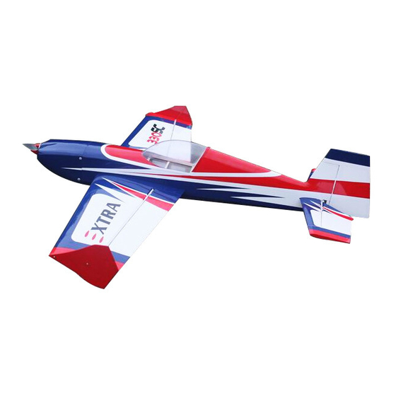
57in EXTRA330SC 50E
Electric Extreme Series
Specifications
Wing Span: 57" ( ( ( ( 1450mm) ) ) )
Length: : : : Including spinner 56"( ( ( ( 1430mm) ) ) )
Wing Area: : : : 687 in²( ( ( ( 44.3dm²) ) ) )
Gross Weight: : : : 4.5 to 5.5 lbs( ( ( ( 2050-2500g) ) ) )
Electric Power: 4250-4255, 220-260g, 1000-1200w class brushless outrunner motors.
ESC:60-80A
Servos: 4 high torque metal gear mini servos (Hitch 5245, 7245)
Batteries: 4S Lipo, 3300-3700mah 6S Lipo, 2200-2600mah
Propellers: 14X6.5-15X6
All contents copyright 2015, GOLDWING RC Version 2.0, May 2015
Advertisement

Related Manuals for Goldwing RC EXTRA330SC 50E


Summary of Contents for Goldwing RC EXTRA330SC 50E
- Page 1 Electric Power: 4250-4255, 220-260g, 1000-1200w class brushless outrunner motors. ESC:60-80A Servos: 4 high torque metal gear mini servos (Hitch 5245, 7245) Batteries: 4S Lipo, 3300-3700mah 6S Lipo, 2200-2600mah Propellers: 14X6.5-15X6 All contents copyright 2015, GOLDWING RC Version 2.0, May 2015...
- Page 2 Dear Customer, Thank you for purchasing the new GoldWing RC Electric Extreme series aircraft. This manual covers the 57in EXTRA330SC 50E aircraft. Goldwing RC proudly presents 57in EXTRA330SC 50E, Electric Extreme (EX) Series, which is a premium product line of electric RC airplanes designed for unlimited 3D performance.
- Page 3 GOLDWING RC WARRANTY AND RETURN POLICY GoldWing RC guarantees this product to be free from defects in both material and workmanship at the date of purchase. This does not cover any parts damaged by use, misuse or modification.
- Page 4 High quality ball link assemblys Extension Lead Safety Clips High Density light Rubber Wheels All contents copyright 2015, GOLDWING RC Version 2.0, May 2015...
- Page 5 Weight only 16g Improved new Axle (the material of Axle is stainless steel ) Weight is only 13g All contents copyright 2015, GOLDWING RC Version 2.0, May 2015...
- Page 6 High performance cap head screws Flat nylon hinges for better flying strength Honeycomb Board carton packing for safer transportation All contents copyright 2015, GOLDWING RC Version 2.0, May 2015...
- Page 7 Extra covering provided for small repairs and Covered in Genuine Ultracote / Oracover The air exit for the electric set up still needs to be inside the fuselage behind the rudder tray. Side Force Generators All contents copyright 2015, GOLDWING RC Version 2.0, May 2015...
- Page 8 Quick release canopy latch Aluminium Backplate Hollowed-out Electric Spinner included (Excellent cooling effect for brushless motor) All contents copyright 2015, GOLDWING RC Version 2.0, May 2015...
- Page 9 Carbon Fiber accessories version: : : : Extra strength Carbon Fiber control Horns One piece air foiled carbon fiber landing gear Light Electric C.F.Tail wheel assembly All contents copyright 2015, GOLDWING RC Version 2.0, May 2015...
- Page 10 Weight only 8g Larger carbon fiber wing tube diameter. All contents copyright 2015, GOLDWING RC Version 2.0, May 2015...
- Page 11 Strengthened fuselage by carbon fiber rods Silvery/red/black Scheme A All contents copyright 2015, GOLDWING RC Version 2.0, May 2015...
- Page 12 White/blue/black Scheme B All contents copyright 2015, GOLDWING RC Version 2.0, May 2015...
- Page 13 White/blue/red Scheme C All contents copyright 2015, GOLDWING RC Version 2.0, May 2015...
- Page 14 RC radio of your choice Shop Supplies/Tools • Covering Iron and heat gun • Hobby tools such as screwdrivers, hobby knife, drill and drill bits, piers, etc. • Thick and Thin CA adhesives All contents copyright 2015, GOLDWING RC Version 2.0, May 2015...
- Page 15 Aircrafts that utilize a very tight double beveled hinge line and do not normally require this step. Sealing the hinge gaps is therefore left as an option for modellers. All contents copyright 2015, GOLDWING RC Version 2.0, May 2015...
- Page 16 Carbon Fiber control Horns (Bag No. KA07NA2A): 2 horns for ailerons, 1 for elevator, and 1 for rudder. • 2.25” Aluminium Backplate Hollowed-out Electric Spinner (Bag No. KAG0202) Color:Scheme A is black, Scheme B is white, Scheme C is red. All contents copyright 2015, GOLDWING RC Version 2.0, May 2015...
- Page 17 Light Electric C.F.Tail wheel assembly (Bag No. KAG0101) • Pushrods kits (Bag No. KA07EB): Two 2x60mm pushrods for ailerons. One 2x80mm pushrods for elevator. One 2x80mm pushrods rudder. • Ball link assembly (Bag No. KAG0011): 8 PCS All contents copyright 2015, GOLDWING RC Version 2.0, May 2015...
- Page 18 • Servo lead safety clips (Bag No. KAG0019):4 pcs • 2.25” main wheels(Bag No. KAG0146):2pcs • New stainless steel Axle kits (Bag No. KA07NH) All contents copyright 2015, GOLDWING RC Version 2.0, May 2015...
- Page 19 • Extra covering provided for small repairs • 3 Hex keys (Bag No. KA07NE) • Side force generators (mounted with four M3X18 hand bolts and 2 balsa sheets) All contents copyright 2015, GOLDWING RC Version 2.0, May 2015...
- Page 20 • 2(3x14mm) hex-head bolts & Washers for landing gear mounting • Screws for cowl: 4(2.5x12mm) stainless steel tapping screws & 4 PTFE Washers All contents copyright 2015, GOLDWING RC Version 2.0, May 2015...
-
Page 21: Rudder Assembly
Insert control horn into base plate then into the slot, trace the edge of base plate with hobby knife then remove the underlying covering. Use some fine sandpaper to roughen up the root of control horn where will be glued into the slot. All contents copyright 2015, GOLDWING RC Version 2.0, May 2015... - Page 22 Feed the servo wires into the fuselage. The screw holes for servo mounting are laser pre-drilled, it is advisable to apply some thin CA to strengthen them, Install the servos and screw firmly in place. All contents copyright 2015, GOLDWING RC Version 2.0, May 2015...
- Page 23 Once satisfied, permanently attach the ball links to the servo arms and horns with the supplied screw and nut. We recommend using KUZA 1.25” aluminium CNC servo arm (sold separately) for rudder control. All contents copyright 2015, GOLDWING RC Version 2.0, May 2015...
-
Page 24: Landing Gear Installation
Press the tubing onto the edges of the fairing as shown and secure glue. 2.3 Bolt the main gear to the bottom of the fuselage using the supplied bolts All contents copyright 2015, GOLDWING RC Version 2.0, May 2015... - Page 25 Use a small drop of thread-lock and tighten in place. Slide the wheel onto the axle and install a second wheel collar also using thread-lock on the set screw. All contents copyright 2015, GOLDWING RC Version 2.0, May 2015...
- Page 26 2.5 Fit the wheel pant in place and install using the 2mm hex-head bolts & Washers. Use thread-lock to secure the screws in place. Repeat the above steps for the other main gear. All contents copyright 2015, GOLDWING RC Version 2.0, May 2015...
- Page 27 2.8 Drill 2 mm holes on the bottom rear of the fuselage, secure the tailwheel bracket with the provided screws. For best results, the pivot point of the assembly should be over the hinge line of the rudder. All contents copyright 2015, GOLDWING RC Version 2.0, May 2015...
-
Page 28: Wing Assembly
Insert control horn into base plate then into the slot, trace the edge of base plate with hobby knife then remove the underlying covering. All contents copyright 2015, GOLDWING RC Version 2.0, May 2015... - Page 29 Fill the slot and coat the root of control horn and the bottom of base plate with 30 minute epoxy, insert the horn into the slot, press it down firmly. Wipe off excessive epoxy with alcohol wipes. Set aside until cured. All contents copyright 2015, GOLDWING RC Version 2.0, May 2015...
- Page 30 Check the final radio operation of the ailerons and make sure there is no binding or servo fighting of each other. Also check to make sure all linkage bolts and nuts are secure. All contents copyright 2015, GOLDWING RC Version 2.0, May 2015...
- Page 31 Removing covering on the central part of horizontal stabilizer is recommended for better glue bonding. Insert the horizontal stabilizer into fuselage, make sure it’s centered. Apply thin and gap-filling medium CA to glue it in place. All contents copyright 2015, GOLDWING RC Version 2.0, May 2015...
- Page 32 Glue the nylon hinges for the elevator with epoxy glue. After installing the elevator, use supplied balsa pieces to fill gap behind the elevator as shown below All contents copyright 2015, GOLDWING RC Version 2.0, May 2015...
- Page 33 Locate the slots for elevator servo, remove covering. Connect wire extension to your servos before feeding the wire into fuselage. Install servo with screws supplied by servo manufacturer. All contents copyright 2015, GOLDWING RC Version 2.0, May 2015...
-
Page 34: Motor Mounting
Double check all screws, bolts and nuts to assure proper installation and operation without binding. Motor Mounting 5.1 Blind nuts are pre-installed behind the firewall. All contents copyright 2015, GOLDWING RC Version 2.0, May 2015... -
Page 35: Cowl Installation
6 Cowl Installation 6.1 Test fit the cowl first, make sure it fits well with canopy and fuselage. 6.2 Drill 2mm holes on cowl and fuselage. All contents copyright 2015, GOLDWING RC Version 2.0, May 2015... - Page 36 7.1 Whether you 72 MHz systems or the newer 2.4 GHz systems, proper radio installation and care is vital to the safe and reliable operation of your aircraft. Follow the manufacturer’s All contents copyright 2015, GOLDWING RC Version 2.0, May 2015...
- Page 37 Note: The best way to check your balance is to trim for level flight at about 1/2 to 3/4 throttle and then roll inverted. The aircraft should maintain level flight with very little to no down All contents copyright 2015, GOLDWING RC Version 2.0, May 2015...
- Page 38 Once you have the wings fully seated in the fuselage tighten the wing bolts inside the fuselage. 9.3 Fixed the SFG Use M3X18 hand bolts and balsa sheets. Installation of the SFG is optional. All contents copyright 2015, GOLDWING RC Version 2.0, May 2015...
- Page 39 9.6 Check your batteries and perform a proper range check once again with the engine off and running. Be sure all surfaces are moving in the correct direction and the proper amount for your flying setup. All contents copyright 2015, GOLDWING RC Version 2.0, May 2015...
- Page 40 Accessories *KUZA Heavy duty aluminum Servo Arm (Not included) FUTABA servo arms HITEC servo arms JR servo arms 26mm/1in for aileron No. KAG0S70F/KAG0S70H/KAG0S70J All contents copyright 2015, GOLDWING RC Version 2.0, May 2015...
- Page 41 32mm/1.25in for elevator & rudder No. KAG0S71F/KAG0S71H/KAG0S71J www.goldwingrc.com All contents copyright 2015, GOLDWING RC Version 2.0, May 2015...
Need help?
Do you have a question about the EXTRA330SC 50E and is the answer not in the manual?
Questions and answers