
Related Manuals for Goldwing RC Extreme Series


Summary of Contents for Goldwing RC Extreme Series
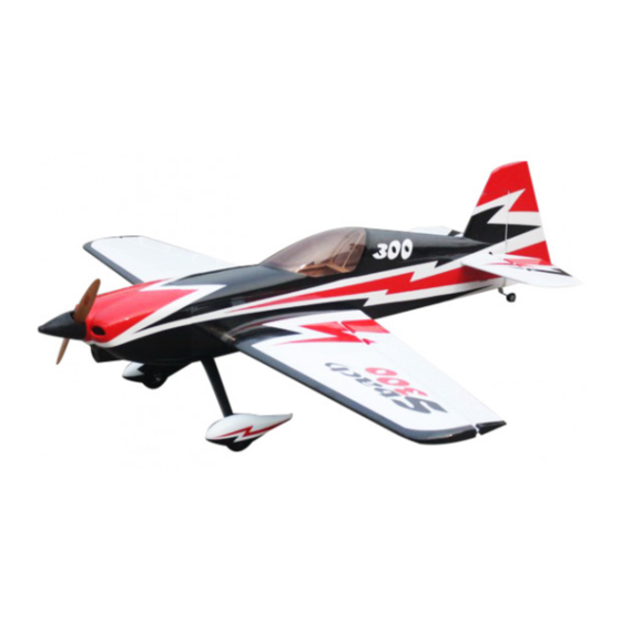
- Page 1 GOLDWING RC 68in SBACH300 90E & 20CC Instruction Manual Two version to choice: 90 Electric or 20CC...
- Page 2 Dear Customer, Thanks for purchasing this newly designed aerobatic RC airplane. Goldwing RC proudly presents 68in SBACH300 90E & 20CC, Extreme Series, which is a premium product line of electric & gas RC airplanes designed for unlimited 3D performance. The new 68in SBACH300 90E & 20CC adopts cutting edge aerodynamic features, such as streamlined canopy, aileron counterbalance, removable side force generators (SFGs) .The 68in SBACH300 is also loaded with high-end accessories including...
-
Page 3: Specifications
SPECIFICATIONS Wing Span: 68"(1720mm) Length: 65"(1650mm) Wing Area: 946sq in(61sq .dm.) Flying Weight: 8-8.8lbs(3600-4000g) Depending on battery size used Engine:.70-.91(2C) .91-.110(4C) 20-26cc gas Electric Power: Hacker A50-16S with 6S 3800-44000mAh 17x8 or 18x8 prop DUSKY XM5060EA-470KV with 6S 3700-4400 mAh 17x8 prop Or other 1500-1800Watt electric motor ESC:80A RADIO:4CH/4-5S... - Page 4 KUZA RTF clear Fuel Tank with Alloy cap for 20CC version Alloy Backplate Hollowed-out Electric Spinner included for 90E version (Excellent cooling effect for brushless motor) Side force generators...
- Page 5 Quick release canopy. Carbon Fiber accessories version: Extra strength carbon fiber control horns One piece air foiled carbon fiber landing gear...
- Page 6 New Carbon fiber tail wheel assembly Strengthened fuselage by carbon fiber rods Carbon fiber wing tube Scheme A white/ red / black...
- Page 7 Scheme B white/ red / blue Scheme C yellow/ red / black...
- Page 8 Items Required to Complete This Model: Two switches with charging jacks for the Rx 1500-1800Watt electric Motor or Two high quality Rx batteries of 20-26CC Gas significant capacity to power your Motor Appropriate propeller for your choice of servos.
- Page 9 Blue thread-lock or equivalent Note: As with all kits, it’s a good idea to read all the instructions and study the parts before you begin construction. Handle the parts of this kit with care so you do not damage any of the structure or covering.
- Page 10 Fiber glass servo horns: 4 single horns for ailerons and elevator. 1 dual horns for rudder. Sand the area of the horn that will be glued to help adhesion. KUZA 260cc RTF clear Fuel Tank with Alloy cap for 20CC version KUZA 75mm(3in) Alloy Backplate Hollowed-out Electric Spinner for 90E version...
- Page 11 Pushrods: Two 2.5x60mm for aileron. Two 2.5x110mm for elevator & rudder (Pull-push style) Ball links: 8 for aileron and elevator. Pull-pull setup for the rudder. 5 Servo extension safety connector clips...
- Page 12 New Carbon fiber tail wheel assembly Screews for landing gear: 4(4x20mm) Hexagon bolts & 4mm stainless steel Self-locking nuts & washers : 4(2.5x12mm) Hexagon socket screws Screews & Washers for cowl & 4 PTFE Washers 4 Hexagon socket screw wrenches...
-
Page 13: Wing Assembly
Motor mounting hardware set Engine mount for nitro and gas engine Wing Assembly NOTE: There are pictures of different planes in this manual, however, this plane’s wings is assembled the same way. It is much easier to install the CFl horns before installing the wing. Locate the CF aileron control horns, ball links, and associated bolts and nylon-insert lock nuts. - Page 14 glue adheres better. Using a sharp hobby knife cut the covering away from the slots in the rudder and trial fit the control horn. Mix up some 30 minute epoxy and coat the inside of the slots and the center of the control horn.
- Page 15 7.Make sure the aileron is fully seated so that the hinge gap is minimal while still allowing full deflection of the aileron. When satisfied, use some masking tape to hold the aileron in place along the bottom and counterbalance. After the epoxy has cured, remove the masking tape and check for proper operation.
-
Page 16: Elevator Assembly
9. Use your radio to set the centers of each servo and then assemble and adjust the length of each control rod. The servo arm should be as close to perpendicular to the control rod as possible while the aileron is at neutral. Double check all screws, bolts and nuts to assure proper installation and operation without binding.Once satisfied, permanently attach the ball link to the servo arm with the supplied screw and nut. - Page 17 3. Glue the hinges for the elevator with CA glue. 4. After installing the elevator, use supplied balsa pieces to fill gap behind the elevator as shown below...
- Page 18 5.Locate the slots for elevator servo, remove covering. Connect wire extension to your servos before feeding the wire into fuselage. Install servo with screws supplied by servo manufacturer. 6.Use your radio to set the servo center position and install the large control horn onto the servo.
-
Page 19: Tail Wheel Installation
Tail Wheel Installation 1. Start tail wheel assembly installation.For safety, please remove all screws and then re-assemble with thread locker. 2. Drill 2 mm holes on the bottom rear of the fuselage, secure the tailwheel bracket with the provided screws. For best results, the pivot point of the assembly should be over the hinge line of the rudder. -
Page 20: Rudder Assembly
NOTE: One spare tail wheel spring is included in the spare hardware pack. Rudder Assembly NOTE: There are pictures of different planes in this manual, however, this plane’s rudder is assembled the same way. 1.Install the fiberglass control horns in the same way as you did the elevator horns. - Page 21 2.The SBACH is supplied with a high quality set of pull-pull cables and ball-links. 3 . Locate the pull-pull cable set, threaded couplers, brass swaging tubes, and ball-links. If the cable is one long piece, cut it into two equal length pieces. Thread one end of the one cable through a brass tube and then through one of the threaded couplers.
- Page 22 location. A coat hanger with a hook on the end can be useful here if you can’t reach the cable. 5.Use your radio system to center the rudder servo and attach either the supplied arm or an appropriate arm for your servo. Thread one of the ball links about half way onto one of the threaded couplers.
-
Page 23: Main Landing Gear Installation
Main Landing Gear Installation NOTE: There are pictures of different planes in this manual, however, this plane’s landing gear is assembled the same way. 1. Bolt the main gear to the bottom of the fuselage using the supplied screws and stainless steel Self-locking nuts. - Page 24 3.Install the wheel axles to the landing gear and tighten the nylon-insert lock nut. Install one wheel collar onto the axle. Use a second wheel collar as a guide to leave a gap on the inboard of the axle. Use a small drop of thread-lock and tighten in place.
-
Page 25: Installation
For 20CC version,Engine, Exhaust, & Fuel System Installation Engine Installation NOTE: There are pictures of different planes in this manual, however, this plane’s engine is assembled the same way. 1. Select the proper guide for your engine and drill the holes and cut out the center as indicated. - Page 26 using bolts, washers, and locknuts. The use of thread-lock is also highly essential for the engine bolts. Mount the ignition module according to the manufacturer’s instructions. best place to mount it is on the side of the engine box. Secure the pickup lead and ignition wires with zip ties so that they do not vibrate or touch any hot part of the engine or exhaust.
- Page 27 Installation of KUZA Fuel Dot and Fuel Vent Line Plug (Not included) 1. KUZA fuel dot and vent line plug. Available in three colors: black, red and blue. 2. Installation of KUZA CNC Aluminum Fuel Dot Sites for KUZA fuel dot installation are pre-cut on both sides of the fuselage, you may install it on either side.
- Page 28 Secure the housing of fuel dot with supplied 2.5 mm self-tapping screws, then plug and install the fuel line to complete the setup of fuel dot.
- Page 29 3. Installation of KUZA CNC Aluminum Fuel Vent Line Plug Similarly, two sites for vent line plug installation are available at the bottom of the fuselage. Secure KUZA vent line plug with four 2.5 mm self-tapping screws as shown below. 90E Electric version Motor Installation Find the hardware set for motor installation in the hardware package.
- Page 30 2. Blind nuts are pre-installed behind the firewall. Since the position of cowl is fixed and length of motors varies, you may need to use provided washers to position you motor properly. 3. Fix the battery with both Velcro and straps.
-
Page 31: Cowling Installation
Cowling Installation NOTE: There are pictures of different planes in this manual, however, this plane’s cowl is assembled the same way. 1. Test fit the cowl first, make sure it fits well with canopy and fuselage. Labels are provided for aligning the drill holes for the cowl. Stick then on without the cowl, mark the hole. - Page 32 3. Secure the cowl with 2.5X12mm self-threading screws and PTFE washers. FINAL RADIO SYSTEM INSTALLATION Whether you 72 MHz systems or the newer 2.4 GHz systems, proper radio installation and care is vital to the safe and reliable operation of your aircraft. Follow the manufacturer’s instruction for installation guidance of receivers and batteries paying attention to factors such as vibration isolation, adequate cooling, and clearances.
- Page 33 Servo clips are provided in the kit for your convenience. These servo clips can even be glued to the wood structure using CA if desired. Check all radio programming and control surface operations thouroughly before your initial flight. Check your radio range according to the radio manufacturer’s instructions both with the engine off and running.
- Page 34 3. Side force generators Assembly. Cut the wing film needed to be instal the SFG. Fixed the SFG Use M3X12 Hexagon socket screw & washer & Self-locking nut. Fill your fuel tank making sure your vent line is not plugged or capped. With the canopy off, this is a good time to check for any fuel leaks.
- Page 35 Check all control surfaces for secure hinges by performed a slight tug on the control surfaces and observing if there is any give in the hinges. Check all control rods, ball links, servo screws, etc. for proper operation and installation. Check your batteries and perform a proper range check once again with the engine off and running.
- Page 36 * KUZA CNC Alloy Fuel Vent Line Plug 3 color to choose: black, blue, red No. KAG0232B or KAG0232U or KAG0232R * KUZA Fuel line clips 10PCS No. KAG02454A...
- Page 37 * KUZA servo arm: For Futaba servo(25T): 39mm/1.5in Single No. KAG0S72F 84mm/3.25in Dual No. KAG0D72F For Hitec servo(24T): 39mm/1.5in Single No. KAG0S72H 84mm/3.25in Dual No. KAG0D72H For JR servo(23T): 39mm/1.5in Single No. KAG0S72J 84mm/3.25in Dual No. KAG0D72J...
- Page 38 * KUZA new Wingbag for 20CC Two color to choose: orange/ silver, blue / silver No. KAG0092 GOLDWING RC www.goldwingrc.com...
Need help?
Do you have a question about the Extreme Series and is the answer not in the manual?
Questions and answers