Advertisement
Quick Links
Advertisement

Related Manuals for Goldwing RC SBACH342 30CC


Summary of Contents for Goldwing RC SBACH342 30CC
- Page 1 GOLDWING RC 73in SBACH342 30CC & 120E Giant Scale Aerobatic Aircraft...
-
Page 2: Specifications
Version 1.0, Jan 2016 Dear Customer, Thank you for purchasing the new Goldwing RC giant scale aerobatic aircraft. This manual covers the 73in SBACH342 30CC and 120E aircraft. The new version 73in SBACH342 adopts cutting edge aerodynamic features, such as streamlined canopy, aileron counterbalance, removable side force generators (SFGs) .The 73in SBACH342 is also loaded with high-end accessories including genuine Oracover, CF landing gear, tail wheel assembly and control horns. - Page 3 Goldwing RC WARRANTY AND RETURN POLICY GoldWing RC guarantees this product to be free from defects in both material and workmanship at the date of purchase. This does not cover any parts damaged by use, misuse or modification. In no case shall liability exceed the original cost of this kit.
- Page 4 Two quick release canopy. New KUZA Fuel Tank with alloy tank cap for 30CC version...
- Page 5 Aluminium Backplate Hollowed-out Electric Spinner included for 120E version (Excellent cooling effect for brushless motor) Including POM & ALU motor washers for 120E version Carbon Fiber accessories version: Extra strength carbon fiber control horns...
- Page 6 One piece air foiled carbon fiber landing gear Carbon fiber tail wheel assembly with CNC machined metal parts, including the aluminium tail wheel hub. 3in Painted carbon fiber spinner for 30CC version...
- Page 7 Increased diameter carbon fiber wing tube over previous versions Scheme A : White /red/black...
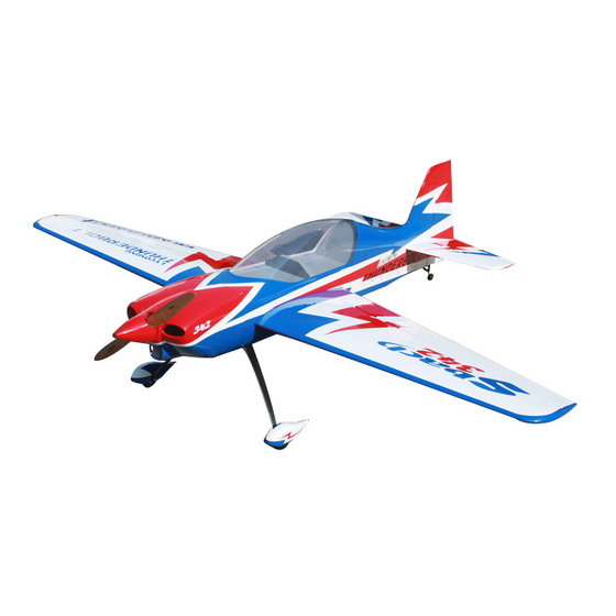
- Page 8 Scheme B : White/Red / blue...
- Page 9 Scheme C : Yellow /red/black...
- Page 10 Items required to complete this model: 26-38 cc gas engine with stock or aftermarket exhaust system Switches with charging jacks for the Rx Appropriate propeller for your engine Rx batteries of significant capacity to power All the required engine and exhaust mounting your choice of servos.
- Page 11 Please verify the accessories before assemble: Carbon Fiber control Horns (Bag No. KA03CA4) : 8 single horns for ailerons and elevator and rudder. Sand the area of the horn that will be glued to help adhesion. KUZA 3” Aluminium Backplate Hollowed-out Electric Spinner for 120E version (Bag No. KAG0205) ...
- Page 12 KUZA new 360cc fuel Tank Assembly for 30CC version (including Aluminum fuel cap) Push rod kits: (Bag No. KA03CB3) Two 2.5x60mm Pushrods for aileron. Two 2.5x130mm Pushrods for elevator.One 2.5x130mm for rudder(Pull-push style) Ball link assembly (Bag No. KAG00122): 8 for ailerons & elevator & rudder.
- Page 13 Alu long arm kits: 4 single arms for ailerons and elevator and rudder. Servo lead safety clips:5 pcs (Bag No. KAG0021) Alu Main wheels:2pcs(Bag No. KAG0157)...
- Page 14 New axle kits (Bag No. KA03CH) Carbon fibre tail wheel assembly with CNC machined metal parts, including the aluminium tail wheel hub. (Bag No. KAGC103) Extra covering provided for small repairs...
- Page 15 4 allen key wrench (Bag No. KA03CE) Side force generators (2 x 3x12mm hex bolts & 2 x 3mm stainless steel self-locking nuts & 2 x washers ) Screews for landing gear: 4(4x20mm) hexagon bolts and 4 washers...
- Page 16 Bolts & washers for cowl: 4(3x14mm) Hexagon bolts and 2(10mm) PTFE washers and 2 wsahers 20 POM & ALU washers for 120E motor Gas engine washers for 30CC version: 12(20mm) POM washers...
-
Page 17: Rudder Assembly
Spares bag(Two spare wing bolts & One spare tail wheel spring) RUDDER ASSEMBLY NOTE: There are pictures of different planes in this manual, however, this plane’s rudder is assembled the same way. 1.It is much easier to install the twin control horns before installing the rudder. Locate the carbon fiber rudder control horns, ball links, and associated bolts and nylon-insert lock nuts. - Page 18 3. Apply 30 minute epoxy to hinges, then insert them into the hinge slots on the rudder, secure the rudder with masking tapes, then allow the epoxy to dry. 4. The SBACH can use either closed loop or a rear push pull servo for the rudder. We recommend that you balance the model assembled before choosing your servo placement.
- Page 19 6. Install your rudder servo into the precut locations in the fuselage. Using a fine drill pre-drill the holes and drop thin CA into the holes to strengthen the wood. You will need 3 inch arms on the servo. Set up your radio accordingly and center the rudder servo.
- Page 20 9. Use your radio system to center the rudder servo and attach either the supplied arm or an appropriate arm for your servo. Thread one of the ball links about half way onto one of the threaded couplers. Feed the loose end of one of the cables through a brass tube and then through the threaded coupler.
- Page 21 12.The SBACH also provides pull-push style for rudder. Below is picture of pull-push style linkage set. Cut off excess carbon fiber rudder horn, and use sandpaper to rough the parts needed to inlay, and use epoxy glue to glue the horn in place.
-
Page 22: Landing Gear Assembly
Use 2.5X130mm push rod between the servo and the rudder horn. We recommend using KUZA 1.5” aluminium CNC servo arm (sold separately) for rudder control. LANDING GEAR ASSEMBLY... - Page 23 NOTE: There are pictures of different planes in this manual, however, this plane’s landing gear is assembled the same way. 1. Locate the supplied main and tail wheel landing gear parts and sort them out on your workbench. 2. Bolt the main gear to the bottom of the fuselage using the supplied screws and stainless steel Self-locking nuts.
- Page 24 4. Install the main wheel axles to the composite landing gear and tighten the nylon-insert lock nut. Install one wheel collar onto the axle. Use a second wheel collar as a guide to leave a gap on the inboard of the axle. Use a small drop of thread-lock and tighten in place.
- Page 25 6. The tail wheel installation is very simple, the factory has installed most of the accessories, see the below picture. 7. Line up the caron fiber assembly onto the body of the aircrtaft and use the holes as a drill guide. Use a 2mm drill bit as a pilot hole, then apply thin CA to harden the wood.
- Page 26 8. Drill another 2mm pilot hole at the end of the rudder and apply thin CA. It needs to be in a position where the spring is tensioned. Use a self tapping screw to secure in place. 9. The below is a picture of correctly installed tail wheel assembly. NOTE: One spare tail wheel spring is included in the spare hardware pack.
-
Page 27: Wings Assembly
WINGS ASSEMBLY NOTE: There are pictures of different planes in this manual, however, this plane’s wings is assembled the same way. 1. Aileron push rod linkage set. 2. The aileron control surfaces is Pre-hingeds. Locate the slots for the aileron control horn and remove the covering with a sharp knife. Place the horns into position and the cover over the top to work out the area needing to be removed. - Page 28 3.Rough the area of the horn that will be glued in place. 4.Using 30 minute epoxy glue the horn and plate into the aileron.
- Page 29 5.Screw holes for servo mounting are pre-drilled by laser in factory, install servo with 4 self threading screws.Fit a metal servo arm centering with your radio. 6.Locate the included aluminum long servo arm, enlarge control holes with 2.5mm drill bit 7.Using the pushrods connect the servo arm to the horn.
-
Page 30: Elevator Assembly
Use M2.5 screws and nuts to connect the pushrod. Set it so the aileron it level when the arm is at 90 degrees. REPEAT FOR THE OTHER SIDE We recommend using KUZA 1.5” aluminium CNC servo arm (sold separately) for wing 8.... - Page 31 1. Push rod linkage set for elevator 2. Find the slots for the control arms in the elevators and remove the covering where the horns are inserted and the area for the plate. 3. Sand the area on the horn that will be glued inside the elevator. 4.
- Page 32 REPEAT FOR THE OTHER SIDE 5. Locate the horizontal stabilizer, use a hobby knife to remove the covering over the area that will be glued to fuselage. It is essential that this is checked for alignment. Place the wing tube in and then look down the fuselage to make sure it is in line.
- Page 33 6. Place long arms onto the servo’s you are planning to use for the elevators. 7. Fit the pushrod in place remembering one end is reverse threaded. Set it so the arm is centered and the elevator is flat. Choose the holes depending on how much deflection you require. 8.
- Page 34 joiner into one elevator half and hinge. Then it will slide onto the other half, and glue in place at the same time as hinging. Dry fit and trim as required to ensure that they are level then glue. 9. We recommend using KUZA 1.5”...
- Page 35 1. Select the correct guide for your engine and drill the holes and cut out the center as indicated. Notice that the engine center line is offset to the left to compensate for the right thrust built into the engine box. 2.
- Page 36 3. The following pictures show how to install a canister. 4. Assemble the throttle servo mount using the supplied laser cut parts or there is a servo cutout in the bottom of the engine box for 28cc-38cc engines. Mount your throttle servo and complete your linkage setup. A hole will need to be drilled on the firewall to allow the pushrod to connect to the throttle arm on the carb.
- Page 37 7. The KUZA new 360cc fuel tank is preassembled. Complete the installation in the fuselage using zip ties or velcro straps to hold the tank in position. Connect a fuel line between the tank and carb, a fuel line between the tank vent and the bottom of the fuselage, and a fill line to a fueling port which can be mounted on the fuselage side opposite your ignition switch.
- Page 38 2. Installation of KUZA CNC Aluminum Fuel Dot Sites for KUZA fuel dot installation are pre-cut on both sides of the fuselage, you may install it on either side. Use shape knife to remove the covering. Secure the housing of fuel dot with supplied 2.5 mm self-tapping screws, then plug and install the fuel line to complete the setup of fuel dot.
- Page 39 3. Installation of KUZA CNC Aluminum Fuel Vent Line Plug Similarly, two sites for vent line plug installation are available at the bottom of the fuselage. Secure KUZA vent line plug with four 2.5 mm self-tapping screws as shown below.
- Page 40 120E Electric version Motor Installation 1. Find the washers for motor installation in the 120E version hardware package.There are 8 POM washers,and 16 ALU washers. 2.Blind nuts are pre-installed behind the firewall. Since the position of cowl is fixed and length of motors varies, you may need to use provided washers to position you motor properly.
-
Page 41: Cowling Installation
3. Fix the battery with both Velcro and straps. COWLING INSTALLATION NOTE: There are pictures of different planes in this manual, however, this plane’s cowling is assembled the same way. 1. The cowl is secured with four 3 X 14mm bolts and washers.Apply nutlock onto the bolts as the vibration from the gas engine will shake them come loose. - Page 42 2. Labels are provided for aligning the drill holes for the cowl. Stick then on without the cowl, mark the hole. Fit the cowl then press back down. The hole will then show the area to drill. Sere below.
- Page 43 To perform properly without being too pitch sensitive, you must not go too aft on the CG. GoldWing RC recommends an initial CG setting of 122-132mm(4.8-5.2 inches) behind the leading edge of the wing at the root. More experienced pilots may want to set the CG further aft for more 3D capability.
- Page 44 Ailerons 25 degrees 35-40 degrees Final Assembly and Pre-Flight Inspections 1. Before arriving at your flying field, be sure all your batteries are properly charged and all radio systems are in working order. 2. Install the wings onto the fuselage being careful to align the wing tube with the wings and not force it. The wing tube may be initially tight but will loosen after some with use.
- Page 45 4. Fill your fuel tank making sure your vent line is not plugged or capped. With the canopy off, this is a good time to check for any fuel leaks. 5. Check all control surfaces for secure hinges by performed a slight tug on the control surfaces and observing if there is any give in the hinges.
- Page 46 * KUZA CNC Aluminum Fuel Dot 3 color to choose: black, blue, red No. KAG0231B or KAG0231U or KAG0231R * KUZA CNC Aluminum Fuel Vent Line Plug 3 color to choose: black, blue, red No. KAG0232B or KAG0232U or KAG0232R...
- Page 47 * KUZA Fuel line clips 10PCS No. KAG02454 * KUZA Heavy duty 7075 aluminum Servo Arm For Futaba servo(25T): 39mm/1.5in Single No. KAG0S72F...
- Page 48 For Hitec servo(24T): 39mm/1.5in Single No. KAG0S72H For JR servo(23T): 39mm/1.5in Single No. KAG0S72J * KUZA new Wingbag for 73in SBACH Two color to choose: red/ black, blue / silver No. KAG0093...
- Page 49 GOLDWING RC www.goldwingrc.com...
Need help?
Do you have a question about the SBACH342 30CC and is the answer not in the manual?
Questions and answers