Table of Contents
Advertisement
Quick Links
www.ti.com
User's Guide
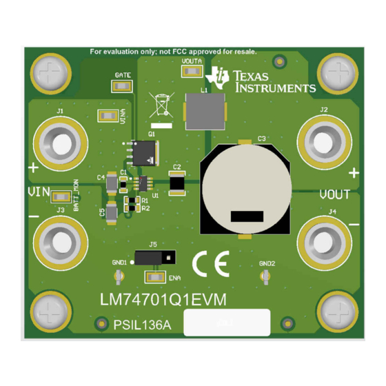
LM74701-Q1EVM User Guide
This user's guide describes the evaluation module (EVM) for TI's ideal diode controller, LM74701-Q1. This
document provides configuration information and test setup details for evaluating LM74701-Q1 devices. An EVM
schematic, board layout images, and bill of materials (BOM) are included.
1
Introduction.............................................................................................................................................................................2
2
Setup........................................................................................................................................................................................2
Description..................................................................................................................................................2
2.2 Board Setup.......................................................................................................................................................................
2.3 Schematic..........................................................................................................................................................................
3 LM74701-Q1EVM Performance Capture...............................................................................................................................
Startup..................................................................................................................................................5
3.2 Startup Reverse Polarity (-12 V).......................................................................................................................................
3.3 ISO 7637-2 Pulse 1 Performance......................................................................................................................................
Drawings....................................................................................................................................................................8
Materials...................................................................................................................................................................9
History....................................................................................................................................................................11
LM74701-Q1EVM......................................................................................................................................................3
Figure 3-1. LM74701-Q1EVM Startup.........................................................................................................................................
Figure 4-2. LM74701-Q1EVM Bottom Side Placement...............................................................................................................
Figure 4-3. LM74701-Q1EVM Top Layer Routing.......................................................................................................................
Materials............................................................................................................................................................9
Trademarks
All trademarks are the property of their respective owners.
SNOU180A - JUNE 2021 - REVISED SEPTEMBER 2021
Submit Document Feedback
ABSTRACT
Table of Contents
Guidelines....................................................................................................8
List of Figures
Circuit............................................................................................................2
Schematic....................................................................................................................................4
V)...............................................................................................................................6
1..............................................................................................................................7
Placement.....................................................................................................................8
Routing..................................................................................................................8
List of Tables
Copyright © 2021 Texas Instruments Incorporated
Table of Contents
3
4
5
6
7
5
8
8
LM74701-Q1EVM User Guide
1
Advertisement
Table of Contents

Related Manuals for Texas Instruments LM74701-Q1EVM


Summary of Contents for Texas Instruments LM74701-Q1EVM
-
Page 1: Table Of Contents
V)..........................6 Figure 3-3. Response to ISO 7637-2 Pulse 1..........................7 Figure 4-1. LM74701-Q1EVM Top Side Placement........................8 Figure 4-2. LM74701-Q1EVM Bottom Side Placement....................... Figure 4-3. LM74701-Q1EVM Top Layer Routing........................Figure 4-4. LM74701-Q1EVM Bottom Layer Routing........................8 List of Tables Table 4-1. Bill of Materials................................9... -
Page 2: Introduction
2 Setup This section describes the jumpers and connectors on the EVM, and how to properly connect, setup, and use the LM74701-Q1EVM. Ensure the power supply is turned off while making connections on the board. 2.1 I/O Connector Description J1: Power input connector to the positive rail of the input power supply... -
Page 3: Board Setup
Make sure that the external power-supply source for the input voltage is capable of providing enough current to the output load so that the output voltage can be obtained. When all connections to the LM74701-Q1EVM are verified, apply power to VIN. Figure 2-2 captures EVM board setup. -
Page 4: Schematic
VCAP CATHODE 0.33µF PEC03SAAN SGND LM74701QDDFQ1 GND1 GND2 BAT T_MON 9.1k BananaJack BananaJack SGND SGND SGND Figure 2-3. LM74701-Q1EVM Schematic LM74701-Q1EVM User Guide SNOU180A – JUNE 2021 – REVISED SEPTEMBER 2021 Submit Document Feedback Copyright © 2021 Texas Instruments Incorporated... -
Page 5: Lm74701-Q1Evm Performance Capture
3 LM74701-Q1EVM Performance Capture 3.1 LM74701-Q1EVM Startup • A startup pulse from 0 V to 12 V is applied at the input of the LM74701-Q1EVM. • Figure 3-1 shows the input voltage (CH2) rises from 0 V to 12 V and the gate voltage (CH3) comes up after input voltage crosses device PoR threshold . -
Page 6: Startup Reverse Polarity (-12 V)
LM74701-Q1EVM Performance Capture www.ti.com 3.2 Startup Reverse Polarity (–12 V) • A –12-V source is connected to the VIN input of the LM74701-Q1EVM. • Figure 3-2 shows that the output voltage remains at a constant 0 V in this situation. -
Page 7: Iso 7637-2 Pulse 1 Performance
“TVS Less” operation is tested on EVM with –100-V ISO7637-2 pulse 1 transient. For additional information on device EMC performance, refer to the data sheet application section.. SNOU180A – JUNE 2021 – REVISED SEPTEMBER 2021 LM74701-Q1EVM User Guide Submit Document Feedback Copyright © 2021 Texas Instruments Incorporated... -
Page 8: Evm Board Assembly Drawings And Layout Guidelines
Figure 4-1 through Figure 4-4 show component placement and layout of this EVM. Figure 4-2. LM74701-Q1EVM Bottom Side Figure 4-1. LM74701-Q1EVM Top Side Placement Placement Figure 4-4. LM74701-Q1EVM Bottom Layer Routing Figure 4-3. LM74701-Q1EVM Top Layer Routing LM74701-Q1EVM User Guide SNOU180A –... -
Page 9: Bill Of Materials
575-8 Keystone Banana Jack, Uninsulated, 8.9mm Header, Header, 3 PIN, 100mil, Tin PEC03SAAN Sullins 100mil, 3x1, Connector Tin, TH Solutions SNOU180A – JUNE 2021 – REVISED SEPTEMBER 2021 LM74701-Q1EVM User Guide Submit Document Feedback Copyright © 2021 Texas Instruments Incorporated... - Page 10 FID5, FID6 nothing to buy or mount. MOSFET, N- DPAK SQD97N06-6M3L-GE3 Vishay- CH, 60 V, 97 Siliconix A, AEC-Q101, DPAK LM74701-Q1EVM User Guide SNOU180A – JUNE 2021 – REVISED SEPTEMBER 2021 Submit Document Feedback Copyright © 2021 Texas Instruments Incorporated...
-
Page 11: Revision History
Added ISO 7637-2 Pulse 1 Performance section....................• Updated Figure 4-1 through Figure 4-4 ......................• Updated Table 4-1 ............................. SNOU180A – JUNE 2021 – REVISED SEPTEMBER 2021 LM74701-Q1EVM User Guide Submit Document Feedback Copyright © 2021 Texas Instruments Incorporated... - Page 12 STANDARD TERMS FOR EVALUATION MODULES Delivery: TI delivers TI evaluation boards, kits, or modules, including any accompanying demonstration software, components, and/or documentation which may be provided together or separately (collectively, an “EVM” or “EVMs”) to the User (“User”) in accordance with the terms set forth herein.
- Page 13 www.ti.com Regulatory Notices: 3.1 United States 3.1.1 Notice applicable to EVMs not FCC-Approved: FCC NOTICE: This kit is designed to allow product developers to evaluate electronic components, circuitry, or software associated with the kit to determine whether to incorporate such items in a finished product and software developers to write software applications for use with the end product.
- Page 14 www.ti.com Concernant les EVMs avec antennes détachables Conformément à la réglementation d'Industrie Canada, le présent émetteur radio peut fonctionner avec une antenne d'un type et d'un gain maximal (ou inférieur) approuvé pour l'émetteur par Industrie Canada. Dans le but de réduire les risques de brouillage radioélectrique à...
-
Page 15: Circuit
www.ti.com EVM Use Restrictions and Warnings: 4.1 EVMS ARE NOT FOR USE IN FUNCTIONAL SAFETY AND/OR SAFETY CRITICAL EVALUATIONS, INCLUDING BUT NOT LIMITED TO EVALUATIONS OF LIFE SUPPORT APPLICATIONS. 4.2 User must read and apply the user guide and other available documentation provided by TI regarding the EVM prior to handling or using the EVM, including without limitation any warning or restriction notices. - Page 16 Notwithstanding the foregoing, any judgment may be enforced in any United States or foreign court, and TI may seek injunctive relief in any United States or foreign court. Mailing Address: Texas Instruments, Post Office Box 655303, Dallas, Texas 75265 Copyright © 2019, Texas Instruments Incorporated...
- Page 17 TI products. TI’s provision of these resources does not expand or otherwise alter TI’s applicable warranties or warranty disclaimers for TI products.IMPORTANT NOTICE Mailing Address: Texas Instruments, Post Office Box 655303, Dallas, Texas 75265 Copyright © 2021, Texas Instruments Incorporated...
Need help?
Do you have a question about the LM74701-Q1EVM and is the answer not in the manual?
Questions and answers