
Related Manuals for Allied Telesis AT-GS950/28PS


Summary of Contents for Allied Telesis AT-GS950/28PS
- Page 1 AT-GS950/48PS AT-GS950/28PS AT-GS950/16PS AT-GS950/10PS Gigabit Ethernet PoE+ Switches Installation Guide 613-001768 Rev E...
- Page 2 Telesis, Inc. be liable for any incidental, special, indirect, or consequential damages whatsoever, including but not limited to lost profits, arising out of or related to this manual or the information contained herein, even if Allied Telesis, Inc. has been advised of, known, or should have known, the possibility of such damages.
- Page 3 Electrical Safety and Emissions Standards This section contains the following: “US Federal Communications Commission” “Industry Canada” “Emissions, Immunity and Electrical Safety Standards” on page 4 “Translated Safety Statements” on page 4 US Federal Communications Commission Radiated Energy Note This equipment has been tested and found to comply with the limits for a Class A digital device pursuant to Part 15 of FCC Rules.
- Page 4 Electrical Safety EN60950-1 (TUV), UL 60950-1 ( Warning Laser Safety: EN60825 Translated Safety Statements Important: The indicates that a translation of the safety statement is available in a PDF document titled Translated Safety Statements on the Allied Telesis website at www.alliedtelesis.com/support.
-
Page 5: Table Of Contents
Contents Preface................................11 Symbol Conventions ..........................12 Contacting Allied Telesis..........................13 Chapter 1 : Overview ............................. 15 Features ..............................16 Front and Back Panels..........................18 Management Software ..........................21 Twisted Pair Ports ............................22 Power over Ethernet (PoE) ........................23 Combo Ports .............................. - Page 6 Contents...
- Page 7 Figure 1: AT-GS950/10PS and AT-GS950/16PS Front Panels................... 18 Figure 2: AT-GS950/28PS and AT-GS950/48PS Front Panels................... 19 Figure 3: AT-GS950/10PS Back Panel..........................20 Figure 4: AT-GS950/16PS and AT-GS950/28PS Back Panels ................... 20 Figure 5: AT-GS950/48PS Back Panel..........................20 Figure 6: PWR LED on AT-GS950/10PS ..........................26 Figure 7: SYSTEM LED on AT-GS950/16PS ........................
- Page 8 List of Figures...
- Page 9 Table 1. Combo Ports .................................24 Table 2. AT-GS950/10PS PWR LED Functional Descriptions ...................26 Table 3. AT-GS950/16PS, AT-GS950/28PS, and AT-GS950/48PS SYS LED Functional Descriptions ......28 Table 4. AT-GS950/10PS L/A and SPD LEDs Functional Descriptions ................29 Table 5. AT-GS950/16PS, AT-GS950/28PS, and AT-GS950/48PS L/A LED Functional Descriptions ......30 Table 6.
- Page 10 List of Tables...
-
Page 11: Preface
Preface This guide contains the installation instructions for the AT-GS950/10PS, AT-GS950/16PS, AT-GS950/28PS, and AT-GS950/48PS Gigabit Ethernet PoE+ Switches. This preface contains the following sections: “Symbol Conventions” on page 12 “Contacting Allied Telesis” on page 13 The AT-GS950/10PS, AT-GS950/16PS, AT-GS950/28PS, and AT-GS950/ 48PS switches may be collectively referred to as GS950/PS Series switches in this guide. -
Page 12: Symbol Conventions
Warnings inform you that an eye and skin hazard exists due to the presence of a Class 1 laser device. Note indicates that a translation of the safety statement is available in a PDF document titled “Translated Safety Statements” on the Allied Telesis website at http://www.alliedtelesis.com/ support. -
Page 13: Contacting Allied Telesis
GS950/PS Series Switches Installation Guide Contacting Allied Telesis If you need assistance with this product, you may contact Allied Telesis technical support by going to the Support & Services section of the Allied Telesis web site at www.alliedtelesis.com/support. You can find links for... -
Page 15: Chapter 1 : Overview
Chapter 1 Overview This chapter provides descriptions of the AT-GS950/10PS, AT-GS950/ 16PS, AT-GS950/28PS, and AT-GS950/48PS Layer 2 Gigabit Ethernet PoE+ Switches and contains the following sections: “Features” on page 16 “Front and Back Panels” on page 18 “Management Software” on page 21 ... -
Page 16: Features
AT-GS950/28PS switch supports 1000Base-SX/LX transceivers. The switches support either two or four slots for SFPs: Two SFP slots on the AT-GS950/10PS and AT-GS950/16PS switches Four SFP slots on the AT-GS950/28PS and AT-GS950/48PS switches Note On the AT-GS950/10PS, AT-GS950/16PS, and AT-GS950/48PS switches, the SFP slots are paired with twisted pair ports on the switch to form combo ports. - Page 17 GS950/PS Series Switches Installation Guide Note See the product data sheets for the specific Allied Telesis SFP modules supported by the GS950/PS Series switches. LEDs Here is a brief description of the port LEDs: Power LED/SYS; refer to “PWR/SYS LEDs” on page 26.
-
Page 18: Front And Back Panels
Twisted Pair Ports AT-GS950/16PS AT-GS950/16 SFP Slots eco-Friendly 10/100/1000Base-T Twisted Pair Ports Button Port and System LEDs Figure 1. AT-GS950/10PS and AT-GS950/16PS Front Panels Figure 2 on page 19 illustrates the front panels of the AT-GS950/28PS and AT-GS950/48PS Gigabit Ethernet Switches. -
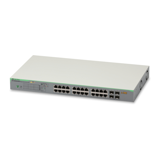
Page 19: Figure 2: At-Gs950/28Ps And At-Gs950/48Ps Front Panels
GS950/PS Series Switches Installation Guide AT-GS950/28PS SFP Slots eco-Friendly 10/100/1000Base-T Button Twisted Pair Ports Port and System LEDs AT-GS950/48PS SFP Slots eco-Friendly 10/100/1000Base-T Button Twisted Pair Ports System LEDs Figure 2. AT-GS950/28PS and AT-GS950/48PS Front Panels... -
Page 20: Figure 3: At-Gs950/10Ps Back Panel
See Figure 3 for an example of the AT-GS950/10PS back panel. AC Input Figure 3. AT-GS950/10PS Back Panel See Figure 4 for an example of the AT-GS950/16PS and AT-GS950/28PS back panels. AC Input Figure 4. AT-GS950/16PS and AT-GS950/28PS Back Panels See Figure 5 for an example of the AT-GS950/48PS back panel. -
Page 21: Management Software
AT-GS950/16PS Switch AT-S126: refer to the Web Interface User’s Guide for the AT-GS950/28PS Switch In the unlikely event that the management software becomes corrupted or damaged on the switch, you can download the software from the Allied Telesis corporate web site and reinstall it on the switch. For instructions on how to install new management software, see the product documentation listed above. -
Page 22: Twisted Pair Ports
Chapter 1: Overview Twisted Pair Ports The AT-GS950/10PS, AT-GS950/16PS, AT-GS950/28PS, and AT-GS950/48PS Layer 2 Gigabit Ethernet Switches feature 10, 16, 24, and 48 twisted pair ports, respectively. All ports are 10Base-T, 100Base- TX, and 1000Base-TX compliant. You can set the port speeds and duplex modes either automatically with IEEE 802.3u Auto-Negotiation or... -
Page 23: Power Over Ethernet (Poe)
GS950/PS Series Switches Installation Guide Power over Ethernet (PoE) Warning To reduce the risk of electric shock, the PoE ports on this product must not connect to cabling that is routed outside the building where this device is located. Power over Ethernet technology permits both power and data to be transmitted over an Ethernet cable. -
Page 24: Combo Ports
The AT-GS950/10PS and AT-GS950/16PS switches have two combo ports, and the AT-GS950/48PS switch has four combo ports. Note The AT-GS950/28PS switch does not have combo ports. Each combo port consists of one 10/100/1000Base-T twisted pair port and one slot for an optional 100Base-FX or 1000Base-SX/LX SFP transceiver. - Page 25 GS950/PS Series Switches Installation Guide An exception to the shared settings is port speed. If you disable Auto-Negotiation on a twisted pair port and set the speed and duplex mode manually, the speed reverts to Auto-Negotiation when an SFP module establishes a link with an end node.
-
Page 26: Leds
The switch is receiving AC input power and is Green operating normally. On the AT-GS950/16PS, AT-GS950/28PS, and AT-GS950/48PS switches, the power and FAN status is indicated with a SYSTEM or SYS LED. See Figure 7 on page 27, Figure 8 on page 27, and Figure 9 on page... -
Page 27: Figure 7: System Led On At-Gs950/16Ps
GS950/PS Series Switches Installation Guide SYSTEM LED Figure 7. SYSTEM LED on AT-GS950/16PS SYS LED Figure 8. SYS LED on AT-GS950/28PS SYS LED Figure 9. SYS LED on AT-GS950/48PS Table 3 on page 28 describes the functions for the SYSTEM/SYS LED for... -
Page 28: Figure 10: At-Gs950/10Ps Link/Activity And Speed Leds
Chapter 1: Overview Table 3. AT-GS950/16PS, AT-GS950/28PS, and AT-GS950/48PS SYS LED Functional Descriptions State Description Either the switch is not receiving power or the AC input power is operating outside the normal range. SYSTEM/ Steady The switch is receiving AC input power and is Green operating normally. -
Page 29: Figure 11: At-Gs950/16Ps Link/Activity/Speed Leds
The maximum operating speed of the Green port is 1000 Mbps. AT-GS950/16PS and AT-GS950/28PS Link/Activity/Speed LEDs The AT-GS950/16PS and AT-GS950/28PS switches have one LED per port on the front panel to indicate link, activity and speed status. See Figure 11 and Figure 12. Link/Activity (L/A)/ Speed LEDs Figure 11. -
Page 30: Figure 13: At-Gs950/48Ps Link/Activity/Speed Port Leds
These LEDs are located next to each port. See Figure 13. Link/Activity (L/A)/Speed LEDs Figure 13. AT-GS950/48PS Link/Activity/Speed Port LEDs See Table 5 for a description for the AT-GS950/16PS, AT-GS950/28PS, and AT-GS950/48PS Link/Activity/Speed LEDs. Table 5. AT-GS950/16PS, AT-GS950/28PS, and AT-GS950/48PS L/A LED Functional Descriptions... -
Page 31: Figure 14: At-Gs950/10Ps Sfp Status Leds
To toggle on the LEDs, use the eco-Friendly button. See “eco-Friendly Button” on page 36 for more information. The AT-GS950/10PS, AT-GS950/16PS, and AT-GS950/28PS switches have the SFP LEDs on the front panel. See Figure 14, Figure 15, and Figure 16. -
Page 32: Figure 17: At-Gs950/48Ps Sfp Status Leds
The SFP transceiver has established a link Amber with a network device at 100 Mbps, but is not transmitting or receiving network packets. Table 7 on page 33 describes the Link LEDs for the SFP slots on the AT-GS950/28PS switch. -
Page 33: Table 7. Sfp Slot Led Functional Descriptions - At-Gs950/28Ps
See Figure 19 on page 34 for the location of the PoE LEDs. The AT-GS950/28PS switch can supply PoE power to PDs on ports 1 - 24. See Figure 20 on page 34 for the location of the PoE status LEDs. -
Page 34: Figure 18: At-Gs950/10Ps Poe And Poe Max Leds
PoE Port LEDs PoE MAX LED Figure 19. AT-GS950/16PS PoE and PoE MAX LEDs PoE Port LEDs PoE MAX LED Figure 20. AT-GS950/28PS PoE and PoE MAX LEDs PoE MAX LED PoE Port LEDs Figure 21. AT-GS950/48PS PoE and PoE MAX LEDs... -
Page 35: Table 8. Poe Status Led Functional Descriptions
GS950/PS Series Switches Installation Guide See Table 8 for a functional description of the PoE status LEDs. Table 8. PoE Status LED Functional Descriptions LEDs State Description The total PoE output power for all ports on the switch exceeds the maximum PoE power that the switch can deliver. -
Page 36: Eco-Friendly Button
Chapter 1: Overview eco-Friendly Button The eco-Friendly button serves multiple functions. See Figure 22 for its location. By pressing this button, you can: Toggle the front panel LEDs on and off to conserve electricity when you are not physically monitoring the switch. Reboot your switch while maintaining the current configuration. - Page 37 GS950/PS Series Switches Installation Guide Reset the switch to factory default settings: By pressing the button for more than 10 seconds, you initiate a software reboot of the switch followed by a reset of the switch to its factory settings. Reboot/Reset the Use the following procedure to reboot the switch or reboot the switch and reset the switch to its factory default settings with the eco-Friendly button:...
-
Page 38: Power Supply
Chapter 1: Overview Power Supply Each switch has an internal power supply with a single AC power supply socket on the back panel. To power the switch on or off, connect or disconnect the power cord provided with the switch. A power cord is supplied with the switch. -
Page 39: Fans
GS950/PS Series Switches Installation Guide Fans The AT-GS950/16PS, AT-GS950/28PS, and AT-GS950/48PS switches have internal fans. You cannot remove or replace these fans in the field. The fan status is indicated with the SYSTEM LED. See “PWR/SYS LEDs” on page 26 for more information. - Page 40 Chapter 1: Overview...
-
Page 41: Chapter 2 : Installation
Chapter 2 Installation This chapter contains the following sections: “Reviewing Safety Precautions” on page 42 “Selecting a Site for the Switch” on page 46 “Cable Specifications” on page 47 “Unpacking the Switch” on page 48 “Installing the Switch on a Desktop” on page 50 ... -
Page 42: Reviewing Safety Precautions
Note indicates that a translation of the safety statement is available in a PDF document titled “Translated Safety Statements” on the Allied Telesis website at http://www.alliedtelesis.com/ support. Warning Class 1 Laser product. - Page 43 GS950/PS Series Switches Installation Guide Warning Class I Equipment. This equipment must be earthed. The power plug must be connected to a properly wired earth ground socket outlet. An improperly wired socket outlet could place hazardous voltages on accessible metal parts. ...
- Page 44 E113 Wall-Mount Orientation Installation Requirements The AT-GS950/28PS unit must be installed with the RJ45 connectors facing up (toward the ceiling) or down (toward the floor) and cannot be installed with the RJ45 connectors facing right or left. See Figure 23 on...
-
Page 45: Figure 23: At-Gs950/28Ps Unit Orientation
GS950/PS Series Switches Installation Guide Correct Orientation Incorrect Orientation Figure 23. AT-GS950/28PS Unit Orientation... -
Page 46: Selecting A Site For The Switch
Chapter 2: Installation Selecting a Site for the Switch Observe the following requirements when choosing a site for your switch: If you plan to install the switch in an equipment rack, verify that the rack is safely secured and will not tip over. Devices in a rack should be installed starting at the bottom, with the heavier devices near the bottom of the rack. -
Page 47: Cable Specifications
GS950/PS Series Switches Installation Guide Cable Specifications Table 9 contains the cable specifications for the twisted pair ports. Table 9. Twisted Pair Cabling and Distances Maximum Speed Type of Cable Operating Distance 10 Mbps Standard TIA/EIA 568-B-compliant 100 m (328 ft) Category 3 or better shielded or unshielded cabling with 100 ohm impedance and a frequency of 16... -
Page 48: Unpacking The Switch
Allied Telesis. 2. Place the switch on a level, secure surface. 3. In addition to an AT-GS950/10PS, AT-GS950/16PS, AT-GS950/28PS, or AT-GS950/48PS switch, verify that the shipping container includes the following items shown in Figure 24 on page 49. -
Page 49: Figure 24: Shipping Package Contents
GS950/PS Series Switches Installation Guide Two equipment rack or wall brackets Eight bracket screws Four wall anchors Four wall screws Four rubber feet (for desktop installation) One regional AC power cord One power cord retaining clip (not included with AT-GS950/48PS) Figure 24. -
Page 50: Installing The Switch On A Desktop
Chapter 2: Installation Installing the Switch on a Desktop You may install the switches on a desktop, in a standard 19-inch equipment rack, or on a wall. To install the switch in a rack, see “Installing the Switch in an Equipment Rack” on page 51. To install the switch on a wall, see “Installing the Switch on a Wall”... -
Page 51: Installing The Switch In An Equipment Rack
GS950/PS Series Switches Installation Guide Installing the Switch in an Equipment Rack To install the switch in a standard 19-inch equipment rack, perform the following procedure: 1. If the rubber feet are attached to the bottom of the switch, remove them using a flat-head screwdriver. -
Page 52: Figure 27: Attaching The Rack-Mount Brackets To The Switch (Continued)
Chapter 2: Installation Figure 27. Attaching the Rack-Mount Brackets to the Switch (Continued) 3. Mount the switch in a standard 19-inch equipment rack using four equipment rack screws (not provided with the switch). Figure 28. Mounting the Switch in an Equipment Rack 4. -
Page 53: Installing The Switch On A Wall
Note The AT-GS950/48PS is too heavy to be safely installed on a wall. To install the AT-GS950/10PS, AT-GS950/16PS, or AT-GS950/28PS switch on a wall, perform the following procedure: 1. Turn the switch over and place it on a table. -
Page 54: Figure 30: Marking The Screw Hole Locations
Chapter 2: Installation 4. Have another person hold the switch at the wall location where the switch is to be installed, while you use a pencil or pen to mark the wall with the locations of the four holes in the brackets. The switch should be oriented such that its front faceplate is facing up and is level to the floor. -
Page 55: Figure 31: Securing The Switch To The Wall
GS950/PS Series Switches Installation Guide 6. While another person holds the switch at the wall location, secure it to the wall using the four wall mounting screws. See Figure 31. Figure 31. Securing the Switch to the Wall 7. Go to “Installing Optional SFP Transceivers” on page 56 or “Cabling the Switch”... -
Page 56: Installing Optional Sfp Transceivers
Chapter 2: Installation Installing Optional SFP Transceivers To install an SFP transceiver, perform the following procedure: Note The transceiver can be hot-swapped; you do not need to power off the switch to install a transceiver. However, always remove the cables before removing the transceiver. Note You should always install the transceiver before connecting the fiber optic cables to it. -
Page 57: Figure 32: Inserting The Sfp
GS950/PS Series Switches Installation Guide 3. Slide the transceiver into the SFP slot until it clicks into place. See Figure 32. Figure 32. Inserting the SFP 4. Verify that the handle on the transceiver is in the upright position, as shown in Figure 33. - Page 58 Chapter 2: Installation 6. Go to “Cabling the Switch” on page 59.
-
Page 59: Cabling The Switch
GS950/PS Series Switches Installation Guide Cabling the Switch Observe the following guidelines when connecting twisted pair and fiber optic cables to the ports on the switch: The connector on the cable should fit snugly into the port on the switch. -
Page 60: Powering On The Switch
Chapter 2: Installation Powering On the Switch To power on the switch, perform one of the following procedures, depending on your model: For AT-GS950/10PS, AT-GS950/16PS, and AT-GS950/28PS switches, refer to “Powering on the AT-GS950/10PS, AT-GS950/ 16PS, and AT-GS950/28PS Switches”. -
Page 61: Figure 35: Raising The Retaining Clip
GS950/PS Series Switches Installation Guide 2. Raise the retaining clip. See Figure 35. Figure 35. Raising the Retaining Clip 3. Connect the power cord to the connector. See Figure 36. Figure 36. Plugging in the AC Power Cord... -
Page 62: Figure 37: Lowering The Retaining Clip
Chapter 2: Installation 4. Lower the retaining clip to secure the power cord to the switch. See Figure 37. Figure 37. Lowering the Retaining Clip 5. Plug the other end of the power cord into a wall outlet. Warning Power cord is used as a disconnection device. To de-energize ... -
Page 63: Figure 38: Plugging In The Ac Power Cord
GS950/PS Series Switches Installation Guide Powering on the To power on the switch, perform the following procedure: AT-GS950/48PS 1. Plug the power cord into the AC power connector on the back of the Switch switch, as shown in Figure 38. Figure 38. -
Page 64: Managing The Switch
AT-S110 Web Interface User’s Guide for the AT-GS950/10PS Switch AT-S111 Web Interface User’s Guide for the AT-GS950/48PS Switch AT-S112 Web Interface User’s Guide for the AT-GS950/16PS Switch AT-S126 Web Interface User’s Guide for the AT-GS950/28PS Switch... -
Page 65: Chapter 3 : Troubleshooting
This chapter contains information on how to troubleshoot the switch if a problem occurs. Note For further assistance, please contact Allied Telesis Technical Support at www.alliedtelesis.com/support. Problem 1: The POWER LED on the front of the switch is off. Solutions: The unit is not receiving power. Try the following: Verify that the power cord is securely connected to the power ... - Page 66 Chapter 3: Troubleshooting Problem 3: A twisted pair port on the switch is connected to a network device, but the port’s LINK/ACT LED is off. Solutions: The port is unable to establish a link to a network device. Try the following: Verify that the network device connected to the twisted pair port is ...
- Page 67 GS950/PS Series Switches Installation Guide Try connecting another network device to the fiber optic port using a different cable. If the port is able to establish a link, then the problem is with the cable or with the other network device. Use the switch’s management software to verify that the port is ...
- Page 68 Chapter 3: Troubleshooting...
-
Page 69: Appendix A: Technical Specifications
Appendix A Technical Specifications Below are the technical specifications for the AT-GS950/10PS, AT-GS950/16PS, AT-GS950/28PS, and AT-GS950/48PS switches. The specification categories are as follows: “Physical Specifications” “Environmental Specifications” on page 70 “Power Specifications” on page 70 “PoE Specifications” on page 70 ... -
Page 70: Environmental Specifications
Input Supply Voltage - 100-240 VAC, 50 - 60 Hz Table 13. Max AC Input Power Specifications AT-GS950/10PS 92.7 W AT-GS950/16PS 228.5 W AT-GS950/28PS 238.0 W AT-GS950/48PS 446.0 W PoE Specifications The maximum number of ports that the GS950/PS Series switches will support when only one class of service is required from the powered devices connected to the PoE ports is shown in Table 14 on page 71. -
Page 71: Safety And Electromagnetic Emissions Certifications
8 Ports 4 Ports 2 Ports AT-GS950/16PS Ports 1 - 16 185 W 16 Ports 12 Ports 6 Ports AT-GS950/28PS Ports 1 - 24 185 W 24 Ports 20 Ports 4 Ports AT-GS950/48PS Ports 1 - 24 370 W 24 Ports... -
Page 72: Table 16. Mdi Pin Signals (10Base-T Or 100Base-Tx)
Appendix A: Technical Specifications Table 16 lists the RJ-45 pin signals when a twisted pair port is operating in the MDI configuration. Table 16. MDI Pin Signals (10Base-T or 100Base-TX) Signal Table 17 lists the RJ-45 port pin signals when a twisted pair port is operating in the MDI-X configuration.
Need help?
Do you have a question about the AT-GS950/28PS and is the answer not in the manual?
Questions and answers