Sign In
Upload
Manuals
Brands
IEI Technology Manuals
Computer Hardware
WSB-H610-DVI-R11
IEI Technology WSB-H610-DVI-R11 Manuals
Manuals and User Guides for IEI Technology WSB-H610-DVI-R11. We have
1
IEI Technology WSB-H610-DVI-R11 manual available for free PDF download: User Manual
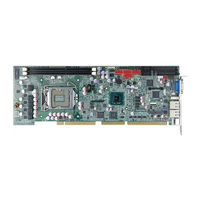
IEI Technology WSB-H610-DVI-R11 User Manual (146 pages)
Brand:
IEI Technology
| Category:
Computer Hardware
| Size: 5 MB
Table of Contents
Table of Contents
5
Introduction
15
Introduction
16
Figure 1-1: WSB-H610
16
Model Variations
17
Features
17
Table 1-1: WSB-H610 Model Variations
17
Connectors
18
Figure 1-2: Connectors
18
Dimensions
19
Figure 1-3: WSB-H610 Dimensions (MM)
19
Figure 1-4: External Interface Panel Dimensions (MM)
20
Data Flow
21
Figure 1-5: Data Flow Diagram
21
Technical Specifications
22
Table 1-2: WSB-H610 Specifications
23
Packing List
24
Anti-Static Precautions
25
Unpacking Precautions
25
Packing List
26
Optional Items
27
Table 2-1: Packing List
27
Table 2-2: Optional Items
29
Connectors
30
Peripheral Interface Connectors
31
WSB-H610 Layout
31
Figure 3-1: Connectors and Jumpers
31
External Interface Panel Connectors
32
Table 3-1: Peripheral Interface Connectors
32
Internal Peripheral Connectors
33
ATX Power Supply Enable Connector
33
Figure 3-2: ATX Power Supply Enable Connector Location
33
Table 3-2: Rear Panel Connectors
33
Table 3-3: ATX Power Supply Enable Connector Pinouts
33
Audio Kit Connector
34
Figure 3-3: Audio Connector Location
34
Table 3-4: Audio Connector Pinouts
34
Battery Connector
35
Figure 3-4: Battery Connector Location
35
Table 3-5: Battery Connector Pinouts
35
CPU Power Input Connector
36
DDR3 DIMM Slots
36
Figure 3-5: ATX Power Connector Pinout Location
36
Table 3-6: ATX Power Connector Pinouts
36
Digital I/O Connector
37
Figure 3-6: DDR3 DIMM Slot Locations
37
Figure 3-7: Digital I/O Connector Location
37
DVI-D Connector (DVI Model Only)
38
Figure 3-8: DVI-D Connector Location
38
Table 3-7: Digital I/O Connector Pinouts
38
EC SPI Flash Connector
39
Figure 3-9: EC SPI Flash Connector Location
39
Table 3-8: DVI-D Connector Pinouts
39
Table 3-9: EC SPI Flash Connector Pinouts
39
Fan Connector (CPU)
40
Floppy Disk Drive Connector
40
Figure 3-10: CPU Fan Connector Location
40
Table 3-10: CPU Fan Connector Pinouts
40
Figure 3-11: Floppy Disk Connector Location
41
Table 3-11: Floppy Disk Connector Pinouts
41
Front Panel Connector
42
Figure 3-12: Front Panel Connector Location
42
Table 3-12: Front Panel Connector Pinouts
42
I2C Connector
43
Infrared Interface Connector
43
Figure 3-13: I2C Connector Location
43
Table 3-13: I2C Connector Pinouts
43
Keyboard/Mouse Connector
44
Figure 3-14: Infrared Connector Location
44
Figure 3-15: Keyboard/Mouse Connector Location
44
Table 3-14: Infrared Connector Pinouts
44
Parallel Port Connector
45
Figure 3-16: Parallel Port Connector Location
45
Table 3-15: Keyboard/Mouse Connector Pinouts
45
Pcie Mini Card Slot
46
Figure 3-17: Pcie Mini Card Slot Location
46
Table 3-16: Parallel Port Connector Pinouts
46
SATA 3Gb/S Drive Connectors
47
Table 3-17: Pcie Mini Card Slot Pinouts
47
Serial Port Connectors, RS-232
48
Figure 3-18: SATA 3Gb/S Drive Connector Location
48
Table 3-18: SATA 3Gb/S Drive Connector Pinouts
48
Serial Port Connector, RS-422/485
49
Figure 3-19: Serial Port Connector Location
49
Table 3-19: Serial Port Connector Pinouts
49
Smbus Connector
50
Figure 3-20: RS-422/485 Connector Location
50
Table 3-20: RS-422/485 Connector Pinouts
50
Table 3-21: DB-9 RS-422/485 Pinouts
50
SPI ROM Connector
51
Figure 3-21: Smbus Connector Location
51
Figure 3-22: SPI ROM Connector Location
51
Table 3-22: Smbus Connector Pinouts
51
TPM Connector
52
Figure 3-23: TPM Connector Location
52
Table 3-23: SPI ROM Connector Pinouts
52
USB Connectors
53
Figure 3-24: USB Connector Pinout Locations
53
Table 3-24: TPM Connector Pinouts
53
Table 3-25: USB Port Connector Pinouts
53
External Peripheral Interface Connector Panel
54
Ethernet Connectors
54
Figure 3-25: External Peripheral Interface Connector
54
Figure 3-26: Ethernet Connector
54
Table 3-26: LAN Pinouts
54
Keyboard/Mouse Connector
55
Figure 3-27: PS/2 Pinout and Configuration
55
Table 3-27: Connector Leds
55
Table 3-28: Keyboard Connector Pinouts
55
USB Connector
56
VGA Connector
56
Table 3-29: USB Port Pinouts
56
Figure 3-28: VGA Connector
57
Table 3-30: VGA Connector Pinouts
57
Installation
58
Anti-Static Precautions
59
Installation Considerations
59
Socket LGA1155 CPU Installation
61
Figure 4-1: Disengage the CPU Socket Load Lever
61
Figure 4-2: Remove Protective Cover
62
Figure 4-3: Insert the Socket LGA1155 CPU
63
Figure 4-4: Close the Socket LGA1155
63
Socket LGA1155 Cooling Kit Installation
64
Figure 4-5: Cooling Kit Support Bracket
64
DIMM Installation
65
Figure 4-6: DIMM Installation
65
Jumper Settings
66
AT/ATX Power Select Jumper
66
Table 4-1: Jumpers
66
Clear CMOS Jumper
67
Figure 4-7: AT/ATX Power Mode Jumper Location
67
Figure 4-8: Clear BIOS Jumper Location
67
Table 4-2: AT/ATX Power Mode Jumper Settings
67
Table 4-3: Clear BIOS Jumper Settings
67
Wake-On LAN Jumper
68
Figure 4-9: Wake-On LAN Jumper Location
68
Table 4-4: Wake-On LAN Jumper Settings
68
Table 4-5: Wake-On LAN Jumper Pinouts
68
Chassis Installation
69
Airflow
69
CPU Card Installation
69
Internal Peripheral Device Connections
69
Dual RS-232 Cable with Slot Bracket
69
DVI-D/USB Kit Installation (DVI Model Only)
70
Figure 4-10: Dual RS-232 Cable Installation
70
SATA Drive Connection
71
Figure 4-11: DVI-D/USB Kit Installation
71
Figure 4-12: SATA Drive Cable Connection
72
USB Cable (Dual Port) with Slot Bracket
73
Figure 4-13: SATA Power Drive Connection
73
Pcie Mini Card Installation
74
Figure 4-14: Dual USB Cable Connection
74
External Peripheral Interface Connection
75
LAN Connection
75
Figure 4-15: Pcie Mini Card Installation
75
USB Device Connection (Single Connector)
76
Figure 4-16: LAN Connection
76
VGA Monitor Connection
77
Figure 4-17: USB Device Connection
77
Figure 4-18: VGA Connector
78
Bios
79
Introduction
80
Starting Setup
80
Using Setup
80
Getting Help
81
Unable to Reboot after Configuration Changes
81
BIOS Menu Bar
81
Table 5-1: BIOS Navigation Keys
81
Main
82
BIOS Menu 1: Main
82
Advanced
83
ACPI Settings
84
BIOS Menu 2: Advanced
84
BIOS Menu 3: ACPI Configuration
84
Trusted Computing
85
BIOS Menu 4: TPM Configuration
85
CPU Configuration
86
BIOS Menu 5: CPU Configuration
86
CPU Information
87
BIOS Menu 6: CPU Configuration
87
SATA Configuration
88
BIOS Menu 7: SATA Configuration
88
Intel TXT(LT) Configuration
89
BIOS Menu 8: Intel TXT(LT) Configuration
89
USB Configuration
90
BIOS Menu 9: USB Configuration
90
Super IO Configuration
91
BIOS Menu 10: Super IO Configuration
91
Floppy Disk Controller Configuration
92
Serial Port N Configuration
92
BIOS Menu 11: Serial Port N Configuration Menu
92
BIOS Menu 12: Serial Port N Configuration Menu
93
Parallel Port Configuration
97
BIOS Menu 13: Parallel Port Configuration Menu
97
H/W Monitor
98
BIOS Menu 14: H/W Monitor
99
CPU_FAN 1 Configuration
100
BIOS Menu 15: FAN 1 Configuration
100
Serial Port Console Redirection
101
BIOS Menu 16: Serial Port Console Redirection
101
Iei Feature
103
Chipset
104
BIOS Menu 17: IEI Feature
104
Northbridge Configuration
105
BIOS Menu 18: Chipset
105
BIOS Menu 19:Northbridge Chipset Configuration
105
Southbridge Configuration
108
BIOS Menu 20: Southbridge Chipset Configuration
108
Integrated Graphics
109
BIOS Menu 21: Integrated Graphics
109
Boot
110
BIOS Menu 22: Boot
110
Security
112
BIOS Menu 23: Security
112
Exit
113
BIOS Menu 24:Exit
113
Software Drivers
115
Available Software Drivers
116
Software Installation
116
Figure 6-1: Introduction Screen
117
Figure 6-2: Available Drivers
117
Chipset Driver Installation
118
Figure 6-3: Chipset Driver Screen
118
Figure 6-4: Chipset Driver Welcome Screen
119
Figure 6-5: Chipset Driver License Agreement
119
Figure 6-6: Chipset Driver Read Me File
120
Figure 6-7: Chipset Driver Setup Operations
120
Graphics Driver Installation
121
Figure 6-8: Chipset Driver Installation Finish Screen
121
Figure 6-9: Graphics Driver Welcome Screen
122
Figure 6-10: Graphics Driver License Agreement
122
Figure 6-11: Graphics Driver Setup Operations
123
Figure 6-12: Graphics Driver Installation Finish Screen
123
Lan Driver Installation
124
Figure 6-13: LAN Driver Welcome Screen
124
Figure 6-14: LAN Driver Installation
125
Figure 6-15: LAN Driver Installation Complete
125
Audio Driver Installation
126
Figure 6-16: Audio Driver - Extracting Files
126
Figure 6-17: Audio Driver Installation Welcome Screen
127
Figure 6-18: Audio Driver Installation
127
Figure 6-19: Audio Driver Installation Complete
127
A Regulatory Compliance
128
BBIOS Options
130
C Terminology
133
D Digital I/O Interface
137
Introduction
138
Assembly Language Sample 1
139
Assembly Language Sample 2
139
E Watchdog Timer
140
F Hazardous Materials Disclosure
143
Hazardous Materials Disclosure Table for IPB Products Certified as Rohs Compliant under 2002/95/EC Without Mercury
144
Advertisement
Advertisement
Related Products
IEI Technology WSB-H610
IEI Technology WSB-H610-R11
IEI Technology WSB-9154
IEI Technology WSB-9454-R40
IEI Technology WSB-9454DVI-R40
IEI Technology WEB-6580
IEI Technology WAFER-ULT4-i3
IEI Technology WAFER-ULT3-i3
IEI Technology WAFER-TGL-U
IEI Technology WAFER-TGL-U-I3-R10
IEI Technology Categories
Motherboard
Touch Panel
Computer Hardware
Single board computers
Desktop
More IEI Technology Manuals
Login
Sign In
OR
Sign in with Facebook
Sign in with Google
Upload manual
Upload from disk
Upload from URL