Table of Contents
Advertisement
Quick Links
Advertisement
Table of Contents

Related Manuals for Tenma 72-9380A


Summary of Contents for Tenma 72-9380A
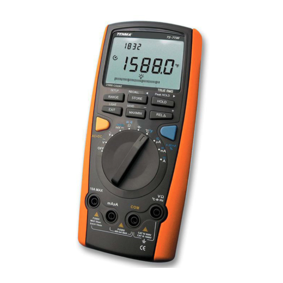
- Page 1 Pocket Size Digital Multimeter Model: 72-9380A...
-
Page 2: Important Safety Information
IMPORTANT SAFETY INFORMATION Please read these instructions carefully before use and retain for future reference. This instrument is designed & manufactured in compliance with: G84793, lEC61010-1, CAT III 1000V, & CAT IV 600V Pollution Degree 2 and Double Insulation standards. •... -
Page 3: Display Backlight
OVERVIEW LCD display Function buttons. Range selector. Input terminals. Automatic Power Off • The display blanks and the meter goes into sleep mode after a 10 minute period of inactivity. • While in Sleep mode, pressing the blue button or turning the range selector will reactivate the meter. -
Page 4: Function Buttons
Function buttons • The buttons activate features that augment the function selected with the range selector. • Press the button once to access the main feature (e.g. STORE). • To access the first additional feature of the button (e.g. RECALL), press and hold the button for over 1 second. - Page 5 Button Description Access Method Press to exit certain button functions and the Press the button once. meter will return to the factory default setting. Press to turn the backlight on. It is possible to EXIT switch between 1st and the 2nd backlight level and Exit the feature by pressing Press and hold the button for this button.
- Page 6 Function Primary Display Right Secondary Display Left Secondary Display The tested DC voltage value No display Full range: 4, 40, 400, 1000 The tested frequency value: The tested AC voltage value Full range: 4, 40, 400, 1000 40.00Hz~ 250.0kHz DCmV The tested DCmV value No display Full range: 400...
-
Page 7: Operation
Analogue Bar Graph • The bar graph provides an analogue indication of the measured input. For most measurement functions, the bar graph updates 10 times per second. • Using MAX MIN • The MAX MIN mode stores minimum (MIN) and maximum (MAX) input values. When the input goes below the stored minimum value or above the stored maximum value, the meter beeps and stores the new value. -
Page 8: Measuring Current
Measuring Current • To measure AC or DC current proceed as follows: Turn off power to the circuit. Discharge all high- voltage capacitors. Insert the red test lead into the mAµA or A terminal and black test lead into the COM terminal. - Page 9 • When testing the resistance signal from the calibrator, it is necessary to press and hold the RANGE while turning on the meter to change the maximum display to 4000 counts but the accuracy remains unchanged. • When resistance measurement has been completed, disconnect the test leads from the circuit under test and remove test leads from the input terminals of the meter.
-
Page 10: Measuring Capacitance
Measuring Capacitance • To ensure accuracy, the meter will first internally discharge the capacitor under test. DIS.C will show on the display. Depending upon the size of the capacitor and the amount of discharge required, this process may take some time. •... - Page 11 Measuring Temperature Note: Do not apply voltage to the test leads when the meter is in temperature measuring mode. Set the range selector to F, the display shows OL. Short circuit the test leads to show the room temperature. The meter is default to Celsius degree unit, you can change units by press the BLUE button once you have selected the temperature function.
- Page 12 Power measurement • Set the rotary switch to W. • Insert the power adaptor to the corresponding input terminals, and plug the power adaptor to the outlet. • Insert the object to be measured into the outlet of the power adaptor. •...
- Page 13 Using Send • When using a Send feature, please refer to the Installation Guide on the included CD-ROM. Changing the Default Setting • The meter allows you to change the default operating configuration by changing setup options made at the factory. •...
-
Page 14: Specifications
SPECIFICATIONS Function Range/description Operating Temperature C (32 F~104 Relative Humidity ≤75%@ 0 C~30 C below ≤50%@ 30 C~40 Battery Type 9V NEDA 1604 or 6F22 or 006P Dimensions (H x W x L) 177 x 85 x 40mm) Weight 340g incl battery Range Auto Polarity... - Page 15 AC Voltage (AC+DC measurement is available) Range Resolution Bandwidth Accuracy Input Impedance 0.0001V 45Hz~1kHz ±(0.4%+30) 1kHz~10kHz ±(3%+30) 10kHz~100kHz ±(6%+30) 0.001V 45Hz~1kHz ±(0.4%+30) 1kHz~10kHz ±(3%+30) 10kHz~100kHz ±(6%+30) Approx 10mΩ 400V 0.01V 45Hz~1kHz ±(0.4%+30) 1kHz~10kHz ±(5%+30) 10kHz~100kHz Not Specified 1000V 0.1V 45Hz~1kHz ±(1%+30) 1kHz~10kHz ±(5%+30)
- Page 16 AC Current (AC+DC measurement is available) Overload Range Resolution Bandwidth Accuracy Protection 400μA 0.01μA 0.5A, 1000V fast 4000μA 0.1μA 45Hz~1kHz ±(0.7%+15) type fuse Ø10.3 1kHz~10kHz ±(1%+40) 400mA 0.001mA x 38mm 400mA 0.01mA 45Hz~1kHz ±(1.5%+20) 10A, 1000V fast 0.001A type fuse Ø6.3 x 1kHz~10kHz ±(5%+40) 32mm...
- Page 17 Capacitance Range Resolution Accuracy Overload Protection 40nF 0.001nF ±(1%+20) + capacitance value of open circuit test leads 400nF 0.01nF 1000V 4μF 0.0001μF ±(1%+20) 40μF 0.001μF 400μF 0.1μF ±(1.2%+20) 0.0001mF ±(5%+20) 40mF 0.001mF Not specified Frequency Range Resolution Accuracy Overload Protection 40Hz 0.001Hz 400Hz...
- Page 18 Temperature (Fahrenheit) Range Resolution Accuracy Overload Protection (4%+50) F~32 ± (1.5%+50) 1000V F~752 ± (3%) F~1832 ± Included is a K-Type (nickel chromium ~ nickel silicon) point contact temperature probe which could only measure temperature below 230 If you want to measure temperature higher than 230 C, you must use the rod contact temperature probe.
-
Page 19: Battery And Fuse Replacement
BATTERY AND FUSE REPLACEMENT • icon appears on LCD, please replace the battery as follows: • Disconnect test probes from circuits being measured, turn range selector to OFF position. • Remove the screw from the battery cover, and separate the battery cover from the rear casing. - Page 20 INFORMATION ON WASTE DISPOSAL FOR CONSUMERS OF ELECTRICAL & ELECTRONIC EQUIPMENT These symbols indicate that separate collection of Waste Electrical and Electronic Equipment (WEEE) or waste batteries is required. Do not dispose of these items with general household waste. Separate for the treatment, recovery and recycling of the materials used. Waste batteries can be returned to any waste battery recycling point which are provided by most battery retailers.
Need help?
Do you have a question about the 72-9380A and is the answer not in the manual?
Questions and answers