Table of Contents
Advertisement
Quick Links
Advertisement
Table of Contents

Subscribe to Our Youtube Channel
Related Manuals for Tenma 72-7780


Summary of Contents for Tenma 72-7780
- Page 1 True RMS Digital Multimeter Model: 72‐7780 User Manual ...
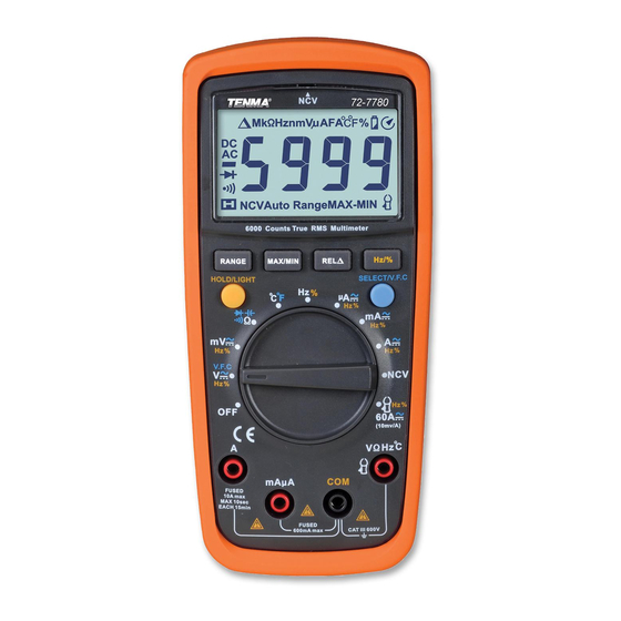
- Page 2 Overview 72‐2800 is a professional handheld true RMS multimeter with wide scope of application. It is a safe, stable and reliable measurement device for AC/DC, resistance, diode, continuity, capacitance, frequency, NCV measurement etc. Unpacking Inspection Open the package box and take out the device. Please check whether the following items are deficient or damaged and contact your supplier immediately if they are. • User manual‐‐‐‐‐‐‐‐‐‐‐‐‐‐‐‐‐‐‐‐‐‐‐‐‐‐‐‐1pc • Test leads‐‐‐‐‐‐‐‐‐‐‐‐‐‐‐‐‐‐‐‐‐‐‐‐‐‐‐‐‐‐‐‐1pair • K‐type thermocouple‐‐‐‐‐‐‐‐‐‐‐‐‐‐‐‐1pc • Optional current clamp Safety information III. Safety Standards • EN 61010‐1:2010 • CAT III 600V, double insulation standard, over voltage standard, and RoHS, pollution grade II Please read and comply with the safety information carefully, or the protection provided by the device may be impaired. 1. Do not use the device if the rear cover is not covered up or it will pose a shock hazard 2. Do not use the device if the device or test leads appear damaged or if you suspect that the device is not operating properly. Pay particular attention to the insulation layers. 3. To avoid false reading, replace the battery when the battery indicator appears. 4. Functional dial should be switched to proper position. 5.
- Page 3 Diode AC/DC Warning Grounding Current clamp Double insulation Comply with European Union Directives General specifications 1) Max voltage between input terminals and earth grounding: See Technical Specifications 2) Fuse Type: 10A Jack: F 10A H 600V Fuse (Φ6x25) mm mA/μA Jack: F 600mA H 600V Fuse (Φ6x32) mm 3) Max Display Value: Capacitance measurement: 9999 Frequency measurement: 9999 Other measurement: 6000 Duty Ratio:1~99.9% Diode: 3.2V Others: 1) Range: Auto/Manual 2) Polarity: Auto 3) Display updates 2~3 times for every second. Overrange Indicator: “OL” 4) Operating temperature: 0˚C~40˚C (32˚F~104˚F) Storage temperature: ‐10 ˚C~50 ˚C (14 ˚F~122 ˚F) Relative humidity: ≤75% at 0 ˚C~30 ˚C; ≤50% at 30 ˚C~40 ˚C ...
- Page 4 Symbol Indication Data hold ━ Negative value AC/DC AC or DC measurement MAX/MIN Maximum or minimum reading Low power Auto Range Auto range selection Diode measurement Continuity measurement Relative measurement Ω、kΩ、MΩ Unit of resistance Hz、kHz、MHz Unit of frequency % Unit of duty ratio mV、V Unit of voltage Unit of current μA、mA、A Unit of capacitance nF、μF、mF ˚C Celsius degree ˚F ...
- Page 5 NCV Non‐contact voltage OFF shutdown Buttons: RANGE: Switch the range mode to auto/manual and then cycle through all ranges. To exit auto/manual mode, press the button for 2 seconds or switch the functional dial. (Only for V ,Ω,I measurement) MAX/MIN:Starts and stops Max/Min recording. To exit this mode, press the button for 2 seconds or switch the functional dial. (Only for V ,Ω,I and ˚C /˚F measurement) REL:Save the first reading as reference value. The second reading=second measurement value‐reference value. To exit his mode, press the button for 2 seconds. (Only for V ,Ω,I and ˚C /˚F and measurement); when measuring capacitance, REL button is only used for eliminating intrinsic value. Hz/%:When measuring AC voltage/ current, press the button to cycle through frequency and duty ratio measurement. SELECT:Select functions. Under AC modes, long press the button until UFC appears to enter VFC measurement mode and measure the variable frequency voltage. Long press gain to exit VFC measurement mode. HOLD:Press the button once to hold the reading. Press again to unlock the reading and enter general measurement modes. Operation instructions To avoid false reading, replace the battery if the battery low power symbol appears. Also pay special attention to the warning sign ...
- Page 6 measurement, short the test leads and use REL function. • If the resistance when shorted is more than 0.5Ω, please check if test leads are loosened or damaged. • When measuring high resistance above 60MΩ, it is normal to take a few seconds to steady the readings. • Resistance measurement can be used to inspect device’s internal fuses.( see figure 4b) • Do not input voltage over DC 60V or AC30V. 3. Continuity measurement (see figure 5) If the resistance being measured is over 150Ω, circuit is in open status, buzzer does not go off. If the resistance less than 10Ω, circuit is in good conduction status, buzzer will continuously go off. Note: • To avoid damage to the device, before measuring continuity, switch off all power supplies and fully discharge all capacitors. • Do not input voltage over DC 60V or AC30V. 4. Diode measurement (see figure 6) “OL” symbol appears when the diode is open or polarity is reversed. For silicon PN junction, normal value: 500 ~ 800mV (0.5 ~ 0.8V). Notes: • Switch off the power supply to the circuit, and fully discharge all capacitors • Voltage for testing diode is about 3.1 V. •...
- Page 7 capacitance) Notes: • If the tested capacitor is shorted or its capacity is over the specified range “OL” symbol will be displayed on the screen. • When measuring large capacitors, it may take a few seconds to obtain steady readings. • Before measuring capacitors (especially for high voltage capacitors), please fully discharge them. 6. Frequency/Duty ratio measurement (see figure 8) At the frequency position, press the Hz/% to select frequency/duty ratio measurement mode. Notes: • Do not input voltage over DC 60V or AC30V. 7. Temperature measurement (see figure 9) Turn on the device, after “OL” symbol appears, insert K‐thermocouple into the device. Note: Only K‐type thermocouple is applicable. The measured temperature should be less than 230˚C/ 446˚F (˚F=˚C*1.8+32) 8. AC/DC current measurement (see figure 10) Connect test leads with the tested circuit in series. Readings under this AC measurement is true RMS. Notes: • Before measuring, switch off the power supply of the circuit. ...
- Page 8 2) Place the device near the measured object. “‐“ symbol indicates the intensity of the electric field. More “‐“ and the higher the buzzer frequency, the higher the electric field intensity. 3) Intensity of electric field * "EF": 0 ~ 50mV * "‐": 50 ~ 100mV * "‐‐": 100 ~ 150mV * "‐‐‐": 150 ~ 200mV * "‐‐‐‐":> 200mV . Notes: Test leads are not required for NCV measurement. 10. Others • The device enters measurement status in 2 seconds after startup. Restart the device,”ErrE” appears. • The device automatically shuts down if there is no operation for 15 minutes. You can wake up the device by pressing any key. To disable auto shutdown, switch the dial to OFF position, long press SELETE button and turn on the device. symbol will disappear with one long beep. Recover the auto‐off function by restarting the device. • Buzzer notification 1) Input voltage ≥ 600V (AC /DC), buzzer will continuously beep indicating measure range is at limit 2) Input current > 10A (AC/DC), buzzer will continuously beep indicating measure range is at limit •...
- Page 9 Input impedance: about 10MΩ. Results might be unstable at mV range when no load is connected. The value becomes stable once the load is connected. Least significant digit ≤±3 Max input voltage: ±600V, when the voltage≥ 600V, "OL” symbol appears and the buzzer goes off.” 2. AC voltage Range Resolution Accuracy 60.00mV 0.01mV ±(1.0%+3) 600.0mV 0.1mV 6.000V 0.001V 60.00V 0.01V ±(0.8%+3) 600.0V 0.1V 600V 1V ±(1.0%+3) VFC 200.0V~600V 0.1/1V ±(4.0%+3) Input impedance: about 10MΩ Display true RMS. Frequency response: 45Hz ~1KHz (LPF 45~400Hz) ...
- Page 10 5. Capacitance Range Resolution Accuracy 9.999nF 0.001nF REL mode:±(4%+10) 99.99nF~999.9μF 0.01nF~0.1μF ±(4%+5) 9.999mF~99.99mF 0.001mF~0.01mF ±10% Overload protection: 600V‐PTC Test capacitance≤100nF, adapt REL mode. 6. Frequency/Duty ratio Range Resolution Accuracy 9.999Hz~9.999MHz 0.001Hz~0.001MHz ±(0.1%+4) 0.1%~99.9% 0.1% Only for reference Overload protection: 600V‐PTC Input range: (DC level=0) ≤100kHz: 100mVrms≤a≤20Vrms > 100 kHz~1MHz: 200mVrms≤a≤20Vrms >1MHz: 500mVrms≤a≤20Vrms ...
- Page 11 μA mA range: F1Fuse (φ6×32)mm FF 600mA H 600V 10 A range:F2Fuse (φ6×25)mm FF 10A H 600V 9. AC current Range Resolution Accuracy 600.0μA 0.1μA μA 6000μA 1μA ±(1.0+3) 60.00mA 10μA mA 600.0mA 0.1mA 6.000A 1mA A ±(1.2%+3) 10.00A 10mA Frequency response: 45~1kHz Display: true RMS ...
- Page 12 Fuse replacement: 1) Switch the dial to “OFF “position and remove the teat leads from the input terminal 2) Loosen the both screws on the rear cover, and then remove the rear cover to replace the fuse Fuse specification F1 Fuse φ6×32mm FF 600mA H 600V F2 Fuse φ6×25mm FF 10A H 600V Tenma Test Equipment 405 S. Pioneer Blvd. Springboro, Oh ...
Need help?
Do you have a question about the 72-7780 and is the answer not in the manual?
Questions and answers