Table of Contents
Advertisement
Quick Links
Advertisement
Table of Contents

Related Manuals for Tenma 72-9375


Summary of Contents for Tenma 72-9375
- Page 1 72-9375 110V P/N:110401102691...
-
Page 2: Table Of Contents
72-9375: OPERATING MANUAL Table of Contents Title Page Overview…………………………………………………2 Package Contents………………………………………2 Safety Information………………………………………2 Rules for Safe Operation………………………………3 International Electrical Symbols……………………….4 The Meter Structure…………………………………….5 Rotary Switch……………………………………………5 Functional Buttons………………………………..6 Display Symbols…………………………………..6 Measurement Operation……………………………..8 AC & DC Voltage Measurement……………….8 Measuring Resistance, Diodes, Continuity &... -
Page 3: Overview
To avoid electric shock or personal injury, read the “Safety Information” and “Rules for Safe Operation” carefully before using the Meter. The Tenma 72-9375 (hereafter referred to as “the Meter”) is a 4000 counts, 3 3/4 digits solar powered auto ranging electrical tester with stabilized functions, safe design, and reliable performance. -
Page 4: Rules For Safe Operation
72-9375: OPERATING MANUAL 1000V, CAT. III 600V) and double insulation. Use the Meter only as specified in this operating manual, otherwise the protection provided by the Meter may be impaired. In this manual, a Warning identifies conditions and actions that pose hazards to the user, or may damage the Meter or the equipment under test. -
Page 5: International Electrical Symbols
72-9375: OPERATING MANUAL range shall be made during measurement is conducted to prevent damage of the Meter. Disconnect circuit power and discharge all high-voltage capacitors before testing current, resistance, diodes, continuity or capacitance. Start charging as soon as the power indicator appears. -
Page 6: The Meter Structure
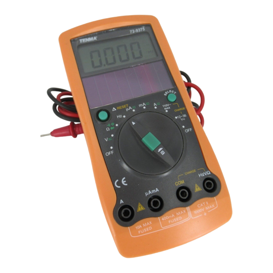
72-9375: OPERATING MANUAL Warning. Refer to Conforms the Operating Manual Standards of European Union The Meter Structure (see figure 1) LCD Display Solar Panel SELECT Button Rotary Switch HOLD Button Input Terminals Relative Mode & RESET Button Rotary Switch Below table indicated for information about the rotary switch positions. -
Page 7: Functional Buttons
72-9375: OPERATING MANUAL Charge at 110VAC. 12-36 : Charge at 12-36 Functional Buttons Below table indicated for information about the functional button operations. Measuring Operation Performed Button Function Any rotary Press RESET to switch enter and exit the position mode in any measuring... - Page 8 72-9375: OPERATING MANUAL Symbol Meaning Indicator for AC voltage or current. The displayed value is the mean value. Indicates negative reading. Charge indicator CHARGE The Meter is in the auto range AUTO mode in which the Meter automatically selects the range with the best resolution.
-
Page 9: Measurement Operation
72-9375: OPERATING MANUAL µF, nF Farad (unit of capacitance) µF: Microfarad. 1 x 10 0.000001 farads. Nanofarad. 1 x 10 0.000000001 farads. Hz, kHz, Hertz (The unit of frequency in cycles/second. kHz: Kilohertz. 1 x 10 or 1,000 hertz. MHz: Megahertz. - Page 10 72-9375: OPERATING MANUAL AC voltage measurement The AC voltage ranges are: 4.000V, 40.00V, 400.0V and 750.0V. To measure AC Voltage, connect the Meter as follows: Insert the red test lead into the HzV terminal and the black test lead into the COM terminal.
-
Page 11: Measuring Resistance, Diodes, Continuity & Capacitance
72-9375: OPERATING MANUAL Note At 400mV range, the Meter has an input impedance of 4000M . Except at 400mV range, all other ranges the Meter has an input impedance of 10M . This loading effect can cause measurement errors in high impedance circuits. - Page 12 72-9375: OPERATING MANUAL Insert the red test lead into the HzV terminal and the black test lead into the COM terminal. Set the rotary switch to , resistance measurement ( ) is default (or press SELECT button to select measurement mode) Connect the test leads with the object being measured.
- Page 13 72-9375: OPERATING MANUAL other semiconductor devices. The diode test sends a current through the semiconductor junction, and then measures the voltage drop across the junction. good silicon junction drops between 0.5V and 0.8V. To test a diode out of a circuit, connect the Meter as...
- Page 14 72-9375: OPERATING MANUAL To test for continuity, connect the Meter as below: Insert the red test lead into the HzV terminal and the black test lead into the COM terminal. Set the rotary switch to and press SELECT button to select measurement mode.
-
Page 15: Frequency Measurement
72-9375: OPERATING MANUAL accuracy of capacitance measurement, press button before measuring (the LCD will display 0). Connect the test leads with the object being measured. The measured value shows on the display. Note The LCD displays OL indicating the capacitor is short-circuited or the capacitor value being tested is overload. -
Page 16: Ac & Dc Current Measurement
72-9375: OPERATING MANUAL Note When Hz measurement has been completed, disconnect the connection between the testing leads and the circuit under test. AC & DC Current Measurement (see figure 9) Warning Never attempt an in-circuit current measurement where the open-circuit voltage between the circuit and ground is greater than 110V. -
Page 17: Power Charging
72-9375: OPERATING MANUAL Set the rotary switch to A , mA or A . The Meter defaults to DC current measurement mode. To toggle between DC and AC current measurement function, press SELECT button. AC current is displayed as an mean value (calibrated against sine wave effective value). -
Page 18: Operation Of Hold Mode
72-9375: OPERATING MANUAL To set up charging as follows: Charge at 110V AC Insert the red test lead into the HzV terminal and the black test lead into the COM terminal. Set the rotary switch to 110V MAX. Insert the test leads’ probe tip into the 110V AC power supply respectively. -
Page 19: The Use Of Relative Value Mode
72-9375: OPERATING MANUAL power. The Hold mode will not capture unstable or noisy readings. The Hold mode is applicable to all measurement functions. Press to enter Hold mode (meter will beep) Press again to exit Hold mode (meter will beep) In Hold mode, is displayed. -
Page 20: The Reset Button
72-9375: OPERATING MANUAL The RESET button The RESET mode applies only to the charge function. The LCD will be closed when the power is low. When the LCD is first opened or charging after 5 minutes during power charging, press RESET to display the correct current charging voltage. -
Page 21: Accuracy Specifications
72-9375: OPERATING MANUAL Electro-Magnetic Field Interference: When field value is under 1V/m: total accuracy = assigned accuracy + 5% of the range. When field value is over 1V/m: there is no assigned accuracy Battery Deficiency: Display Negative reading:Display Overloading: Display: OL. -
Page 22: Dc Voltage
72-9375: OPERATING MANUAL B. DC Voltage Overload Range Resolution Accuracy Protection 400m 0.1mV ±(0.8%+3) 1000V DC 1 mV or 750V AC ±(0.8%+1) continuous 10 mV 400V 100mV 1000V ±(1%+3) Remark: Input impedance: At 400mV range: above 4000M All other ranges: approx. 10M C. -
Page 23: Capacitance Test
72-9375: OPERATING MANUAL resistance value is 10 (The closed circuit is in working condition). E. Capacitance Test Overload Resoluti on Accurac y Range Protection ±(3%+10) 40nF 10pF 400nF 100pF 600Vp ±(3%+5) 4μF 40μF 10nF 100μF 100nF ±(4%+5) F. Frequency Test... -
Page 24: Dc Current
72-9375: OPERATING MANUAL 15 minutes rest intervals between tests) H. DC Current Overload Range Resolution Accuracy Protection 400 A 0.1 A Fuse 500mA, ±(1%+2) 4000 250V, fast type, 40mA 10 A ±(1.2%+ 3) 5×20mm 400mA 0.1mA Fuse 10A, 250V, fast ±(1.5%+5) -
Page 25: Replacing The Fuses
72-9375: OPERATING MANUAL high temperature, explosives, and strong magnetic field. Replacing the Fuses (see figure 11) Warning To avoid electrical shock or arc blast, which would cause personal injury or damage to the Meter, use specified fuses ONLY in accordance with the following procedure.
Need help?
Do you have a question about the 72-9375 and is the answer not in the manual?
Questions and answers