
Related Manuals for Tenma 72-1015


Summary of Contents for Tenma 72-1015
- Page 1 Bench Digital Multimeter User Manual Part Number: 72-1015 Newark.com/exclusive-brands Farnell.com/exclusive-brands Element14.com/exclusive-brands Page <1> 27/12/19 V1.0...
-
Page 2: Safety Information
To avoid electric shock or personal injury, read the “Safety Information” and “Rules for Safety Operation” carefully before using the Meter. Digital Bench-Type True RMS Multimeter Model 72-1015 (hereafter referred to as “the Meter”) has auto and manual range options with maximum reading of 5999 counts and 3-5/6 digits which has a unique outlook design. -
Page 3: Rules For Safe Operation
Rules For Safe Operation Warning To avoid possible electric shock or personal injury, and to avoid possible damage to the Meter or to the equipment under test, adhere to the following rules: • Before using the Meter inspect the case. Do not use the Meter if it is damaged or the case (or part of the case) is removed. Look for cracks or missing plastic. -
Page 4: International Electrical Symbols
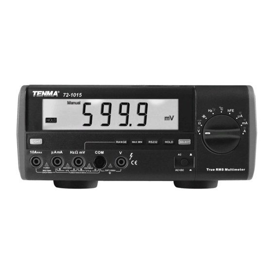
International Electrical Symbols AC or DC Ground Double Insulated Warning. Refer to the Operating Manual Low Battery Continuity Test Diode Capacitance Test Fuse Conforms to Standards of European Union The Meter Structure (see figure 1) (Figure 1) 1. LCD Display 2. -
Page 5: Functional Buttons
Rotary Switch Below table indicated for information about the rotary switch positions: Rotary Switch Position Function AC and DC voltage measurement :Continuity test. :Diode test. Ω :Resistance measurement. Capacitance test Frequency measurement. °F Temperature in Fahrenheit °C Temperature in celsius Transistor test AC or DC current measurement range from 0.1uA to 5999uA. - Page 6 Display Symbols (see figure 2) Number Symbol Meaning True RMS Indicator for true rms value. Data hold is active. Sleep Mode feature is enabled. Indicates negative reading. Indicator for AC voltage or current. Indicator for DC voltage or current AC+DC Indicator for AC+DC measurement The input value is too large for the selected range.
-
Page 7: Measurement Operation
Number Symbol Meaning Test of diode The continuity buzzer is on. Auto Range Indicator of Auto or manual range Manual Display of maximum or minimum value. Data output is in progress. The battery is low. Warning: To avoid false readings, which could lead to possible electric shock or personal injury, replace the battery as soon as the battery indicator appears. - Page 8 B. DC or AC Current Measurement (See figure 4) (Figure 4) Warning Before connecting the meter in series with the circuit under test, be sure power to the circuit is off to avoid the possibility of arcing. If the fuse burns out during measurement, the Meter may be damaged and there is risk of personal injury to the operator.
-
Page 9: Measuring Resistance (See Figure 5)
Measuring Resistance (see figure 5) (Figure 5) Warning To avoid damage to the Meter or to the devices under test, disconnect circuit power and discharge all the high-voltage capacitors before measuring resistance. To avoid possible injury, please do not attempt to input voltages higher than 60V DC or 30V AC. - Page 10 D. Testing Continuity (See figure 6) (Figure 6) Warning To avoid damage to the Meter or to the devices under test, disconnect circuit power and discharge all the high-voltage capacitors before testing for continuity. To avoid personal injury, please do not attempt to input voltages higher than 60V DC or 30V AC.
- Page 11 E. Testing Diodes (See figure 7) (Figure 7) Warning To avoid possible damage to the Meter and to the device under test, disconnect circuit power and discharge all high-voltage capacitors before testing diodes. To avoid personal injury, please do not attempt to input voltages higher than 60V DC or 30V AC. Use the diode test to check diodes, transistors, and other semiconductor devices.
- Page 12 F. Capacitance Measurement (See figure 8) (Figure 8) Warning To avoid damage to the Meter or to the equipment under test, disconnect circuit power and discharge all high-voltage capacitors before measuring capacitance. Use the DC Voltage function to confirm that the capacitor is discharged. To measure capacitance, connect the Meter as follows: 1.
- Page 13 G. Frequency Measurement (see figure 9) (Figure 9) Warning To avoid the risk of personal injury, do not attempt to measure frequency with voltage higher than 30V RMS. To measure frequency, connect the Meter as follows: 1. Insert the red test lead into the Hz terminal and the black test lead into the COM terminal. 2.
- Page 14 H. Temperature Measurement (see figure 10) (Figure 10) To measure temperature, connect the Meter as follows: 1. Set the rotary switch to C to measure degree celsius temperature or Hz F and press SELECT button to select measurement mode to measure Fahrenheit. 2.
-
Page 15: Operation Of Hold Mode
I. Measuring Transistor (see figure 11) (Figure 11) To measure transistor, connect the Meter as follows: 1. Insert the multi-purpose socket into the μAmA and Hz input terminal. 2. Set the rotary switch to hFE. 3. Insert the NPN or PNP type transistor to be tested into the corresponding input terminals of the multipurpose socket. 4. -
Page 16: Ac/Ac+Dc Button
Turning on the Display Backlight Warning In order to avoid the hazard arising from mistaken readings in low light situations, please use Display Backlight function. • Press LIGHT button to turn the Display Backlight on. • Press LIGHT button again to turn the Display Backlight •... -
Page 17: General Specifications
General Specifications • Maximum Voltage between any Terminals and Grounding: Refer to different range input protection voltage. Fused Protection for HzΩWmV Input Terminal: 200mA, 250V, fast type, ɸ5 × 20mm (only apply on hFE functions) • • Fused Protection for μAmA Input Terminal: 500mA, 125V, fast type, ɸ5 × 20mm. •... -
Page 18: Accuracy Specifications
Accuracy Specifications Accuracy: ±(a% reading + b digits),guarantee for 1 year. Operating temperature: 23 C ±5 ° ° Relative humidity: not more than 75% RH. Temperature coefficient: 0.1 × (specified accuracy)/1 ° A. DC Voltage Range Resolution Accuracy Overload Protection 600mV 0.1mV ±(0.6%+2) - Page 19 C. DC Current Range Resolution Accuracy Overload Protection 600μA 0.1μA 6000μA 1μA ±(0.5%+3) Fuse 500mA, 125V, fast type, ɸ5 × 20mm. 60mA 0.01mA 600mA 0.1mA ±(0.8%+3) Fuse 10A, 250V, 10mA ±(1.2%+3) fast type, ɸ5 × 20mm. Remarks: • At 5A range: Continuous measurement is allowed. •...
- Page 20 F. Continuity Test Range Resolution Overload Protection Remarks • Open circuit voltage approximate -1.2V. • When circuit disconnected with resistance value > 30Ω, buzzer does not beep. 1Ω 250V rms • When circuit is in good connection with resistance • value ≤70Ω...
- Page 21 J. Temperature Range Resolution Accuracy Overload Protection -40°C to 0°C ± (8%+5) °C 1°C >00C to 400°C ± (1%+7) >400°C to 1000°C ± (2%+10) 250V rms -40°C to 32°C ± (8%+5) °F 1°F >32°F to 752°F ± (1.5%+5) >752°F to 1832°F ±...
- Page 22 B. Replacing the Fuses (see figure 12) (Figure 12) Warning To avoid electrical shock or arc blast, or personal injury or damage to the Meter, use specified fuses ONLY in accordance with the following procedure. To replace the Meter’s fuse: 1.
- Page 23 C. Replacing the Battery (see figure 13) (Figure 13) Warning To avoid false readings, which could lead to possible electric shock or personal injury, replace the battery as soon as the battery indicator “ ” appears when using battery to power on the Meter. To replace the battery: 1.
-
Page 24: Rs232C Serial Port
System Requirements for Installing the 72-1015 Interface Program To use 72-1015 Interface Program, you need the following hardware and software: • An IBM PC or equivalent computer with 80486 or higher processor and 600 × 800 pixel or better monitor. -
Page 25: Setting Of Rs232C Serial Ports
Group was aware of the possibility of such loss or damage arising) is excluded. This will not operate to limit or restrict the Group’s liability for death or personal injury resulting from its negligence. TENMA is the registered trademark of Premier Farnell Limited 2019.
Need help?
Do you have a question about the 72-1015 and is the answer not in the manual?
Questions and answers