Table of Contents
Advertisement
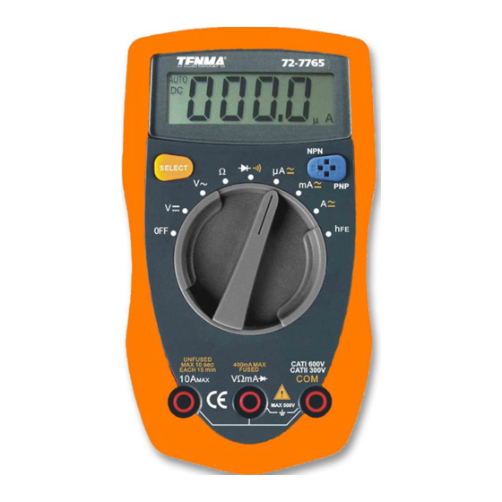
Model 72-7765: OPERATING MANUAL
Accuracy Specifications(4)
D. AC Current
Range
Resolution
400µA
0.1µA
1µA
4000µA
40mA
10µA
400mA
100µA
1mA
4A
10A
10mA
Remark:
l
At 10A Range: For continuous measurement 10 seconds and interval not less
than 15 minutes.
l
Input impedance: approx.
l Measurement voltage drop: Full range at 400mV.
Accuracy
(1.5%+5)
(2%+5)
(2.5%+5)
10MΩ.
33
Overload Protection
500mA/250V fast type
fuse φ 5x20mm
Un-Fused
Advertisement
Table of Contents

Related Manuals for Tenma 72-7765


Summary of Contents for Tenma 72-7765
- Page 1 Model 72-7765: OPERATING MANUAL Accuracy Specifications(4) D. AC Current Overload Protection Range Resolution Accuracy 400µA 0.1µA 500mA/250V fast type (1.5%+5) fuse φ 5x20mm 1µA 4000µA 40mA 10µA (2%+5) 400mA 100µA Un-Fused (2.5%+5) 10mA Remark: At 10A Range: For continuous measurement 10 seconds and interval not less than 15 minutes.
- Page 2 Model 72-7765: OPERATING MANUAL Accuracy Specifications(5) E. Resistance Overload Protection Range Resolution Accuracy (1.2%+2) 400Ω 0.1Ω 1Ω 4kΩ (1%+2) 40kΩ 10Ω 250V DC or AC 100Ω 400kΩ (1.2%+2) 1kΩ 4MΩ (1.5%+2) 40MΩ 10kΩ...
- Page 3 Model 72-7765: OPERATING MANUAL Accuracy Specifications(6) F. Diodes and Continuity Measurement Overload Protection Range Resolution Remark Displays approximate forward voltage drop 250V DC or AC 0.1Ω Buzzer beeps at <100Ω G. Transistor hFE Test Testing Condition Range Remark Test NPN and PNP type transistors.
- Page 4 Model 72-7765: OPERATING MANUAL Maintenance(1) This section provides basic maintenance information including battery and fuse replacement instructions. Warning Do not attempt to repair or service your Meter unless you are qualified to do so and have the relevant calibration, performance test, and service information.
- Page 5 Model 72-7765: OPERATING MANUAL Maintenance(3) B. Replacing the Battery (see figure 8) Warning To avoid false readings, which could lead to possible electric shock or personal injury, SCREW replace the battery as soon as the battery indicator “ ”appears. To replace the battery: 1.
- Page 6 Model 72-7765: OPERATING MANUAL Maintenance(4) 4. Remove the battery from the battery compartment. 5. Replace the battery with a new 1.5V AAA battery. 6. Rejoin the case bottom and case top, and reinstall the screw. C. Replacing the Fuses (see figure 8)
- Page 7 Model 72-7765: OPERATING MANUAL Maintenance(5) 4. Remove the fuse by gently prying one end loose, and then take out the fuse from its bracket. 5. Install ONLY replacement fuses with the identical type and specification as follows and make sure the fuse is fixed firmly in the bracket.
- Page 8 Model 72-7765: OPERATING MANUAL Te n m a Te s t E q u i p m e n t 4 0 5 S . P i o n e e r B l v d . S p r i n g b o r o , O h i o 4 5 0 6 6...
- Page 9 Model 72-7765: OPERATING MANUAL Measurement Operation (4) C. DC Current Measurement (see figure 4) Warning Never attempt an in-circuit current measurement where the voltage between terminals and ground is greater than 60V . If the fuse burns out during measurement, the Meter may be damaged or the operator may be injured.
- Page 10 Model 72-7765: OPERATING MANUAL Measurement Operation (5) VΩmA or 10A Insert the red test lead into the terminal and the black test lead into the COM terminal. 3. Set the rotary switch to an appropriate measurement position in A range. DC measurement is default or press SELECT button to select DC measurement mode.
- Page 11 Model 72-7765: OPERATING MANUAL Measurement Operation (6) D. AC Current Measurement (see figure 4) Warning Never attempt an in-circuit current measurement where the open-circuit voltage between the circuit and ground is greater than 500V. If the fuse burns out during measurement, the Meter may be damaged or the operator may be injured.
- Page 12 Model 72-7765: OPERATING MANUAL Measurement Operation (7) 5. Break the current path to be tested. Connect the red test lead to the more positive side of the break and the black test lead to the more negative side of the break.
- Page 13 Model 72-7765: OPERATING MANUAL Measurement Operation (8) E. Resistance Measurement (see figure 5) Warning To avoid damage to the Meter or to the devices under test, disconnect circuit power and discharge all the high-voltage capacitors before measuring resistance. The Ω ranges are : 400.0Ω, 4.000kΩ, 40.00kΩ, black red 400.0kΩ, 4.000MΩ, and 40.00MΩ,...
- Page 14 Model 72-7765: OPERATING MANUAL Measurement Operation (9) Note The test leads can add 0.1Ω to 0.3Ω of error to resistance measurement. To obtain precision readings in low-resistance measurement, that is the range of 200Ω, short-circuit the input terminals beforehand and record the reading obtained (called this reading as X).
- Page 15 Model 72-7765: OPERATING MANUAL Measurement Operation (10) F. Diode and Continuity Test (see figure 6) Testing Diodes Warning To avoid damage to the Meter or to the devices under test, disconnect circuit power and discharge all the high-voltage capacitors before diodes.
- Page 16 Model 72-7765: OPERATING MANUAL Measurement Operation (11) To test a diode out of a circuit, connect the Meter as follows: 1. Insert the red test lead into the VΩmA terminal and the black test lead into the COM terminal. 2. Set the rotary switch to Diode measurement is default or press SELECT button to select diode measurement mode.
- Page 17 Model 72-7765: OPERATING MANUAL Measurement Operation (12) l When diode testing has been completed, disconnect the connection between the testing leads and the circuit under test. Testing for Continuity To test for continuity, connect the Meter as below: 1. Insert the red test lead into the VΩ mA terminal and the black test lead into the COM terminal.
- Page 18 Model 72-7765: OPERATING MANUAL Measurement Operation (13) G. Transistor hFE Measurement (see figure 7) Warning To avoid damages to the Meter or to the devices under test, do not input any current over 60V DC or 30V AC. 1. Check that the transistor is PNP or NPN type.
- Page 19 Model 72-7765: OPERATING MANUAL Sleep Mode To preserve battery life, the Meter automatically turns off after 30minutes of inacjivity. The Meter can be activated by pressing the SELECT button or turning the rotary switch.
- Page 20 Model 72-7765: OPERATING MANUAL General Specifications(1) Maximum Voltage between any Terminals and Ground: 500V rms. Fused Protection for VΩmA Input Terminal: 500mA, 250V fast type, φ5x20 mm 10A Terminal: Un-fused. Range: Auto ranging Maximum Display: Display: 3999. Measurement Speed: Updates 3 times / second.
- Page 21 Model 72-7765: OPERATING MANUAL General Specifications(2) Battery Type: Two piece of 1.5V AAA Battery. Low Battery : Display: Negative reading: Display: “-“. “ ” Overloading: Display: Dimensions (HxWxL): 130 x 73.5 x 35mm. Weight: Approx. 156g (battery included). Safety/Compliances: IEC61010 CAT I 600V, CAT II 300V overvoltage and double insulation standard.
- Page 22 Model 72-7765: OPERATING MANUAL Accuracy Specifications(1) Accuracy: (a% reading + b digits), guarantee for 1 year. Operating temperature: 23 C -5 Relative humidity: <75%. A. DC Voltage Overload Protection Range Resolution Accuracy 100µV (0.8%+3) 400mV 500V DC or AC (0.8%+1)
- Page 23 Model 72-7765: OPERATING MANUAL Accuracy Specifications(2) B. AC Voltage Overload Protection Range Resolution Accuracy (1.2%+3) 500V DC or AC 10mV 400V 100mV (1.5%+5) 500V Remarks: Input impedance: approx. 10MΩ. Displays effective value of sine wave (mean value response). Frequency response 40Hz ~ 400Hz.
- Page 24 Model 72-7765: OPERATING MANUAL Accuracy Specifications(3) C. DC Current Overload Protection Range Resolution Accuracy 400µA 0.1µA 500mA/250V fast type (1%+2) fuse φ 5x20mm 1µA 4000µA 40mA 10µA (1.2%+2) 400mA 100µA Un-Fused (1.5%+5) 10mA Remark: At 10A Range: For continuous measurement 10 seconds and interval not less than 15 minutes.
- Page 25 Model 72-7765: OPERATING MANUAL Table of Contents (1) Title Page Overview Unpacking Inspection Safety Information Rules For Safe Operation International Electrical Symbols The Meter Structure Functional Buttons LCD Display Measurement Operation DC Voltage Measurement AC Voltage Measurement DC Current Measurement...
- Page 26 Model 72-7765: OPERATING MANUAL Table of Contents (2) Title Page Sleep Mode General Specifications Accuracy Specifications DC Voltage AC Voltage C. DC Current D. AC Current Resistance Diodes and Continuity Measurement G. Transistor hFE Test Maintenance General Service Replacing the Battery...
- Page 27 To avoid electric shock or personal injury, read the “Safety Information” and “Rules for Safety Operation” carefully before using the Meter. The Model 72-7765 Multimeter (hereafter referred as “the Meter”) is a 3 3/4 digits with steady operations, fashionable design and highly reliable hand-held measuring instrument.
- Page 28 Model 72-7765: OPERATING MANUAL Unpacking Inspection Open the package case and take out the Meter. Check the following items carefully for missing or damaged parts: Item Description English Operating Manual 1 piece 1 pair Test Lead 1 piece Holster In the event you find items missing or damaged, please contact your dealer...
- Page 29 Model 72-7765: OPERATING MANUAL Safety Information(1) Safety Information This Meter complies with the standards IEC61010: in pollution degree 2, overvoltage category (CAT I 600V, CAT II 300V) and double insulation. CAT. I: Signal level, special equipment or parts of equipment, telecommunication, electronic, etc., with smaller transient overvoltages than overvoltages CAT.
- Page 30 Model 72-7765: OPERATING MANUAL Safety Information(2) In this manual, a Warning identifies conditions and actions that pose hazards to the user, or may damage the Meter or the equipment under test. A Note identifies the information that user should pay attention to.
- Page 31 Model 72-7765: OPERATING MANUAL Rules For Safe Operation (1) Warning To avoid possible electric shock or personal injury, and to avoid possible damage to the Meter or to the equipment under test, adhere to the following rules: l Before using the Meter inspect the case. Do not use the Meter if it is damaged or the case (or part of the case) is removed.
- Page 32 Model 72-7765: OPERATING MANUAL Rules For Safe Operation (2) l When the Meter is working at an effective voltage over 60V DC or 42V rms AC, special care should be taken for there is danger of electric shock. l Use the proper terminals, function, and range for your measurements.
- Page 33 Model 72-7765: OPERATING MANUAL Rules For Safe Operation (3) l Remove test leads from the Meter and turn the Meter power off before opening the case. l When servicing the Meter, use only the same model number or identical electrical specifications replacement parts.
- Page 34 Model 72-7765: OPERATING MANUAL International Electrical Symbols AC or DC AC Current DC Current Ground Double Insulated. Low Battery Diode. Fuse. Continuity Test Warning. Refer to the Operating Manual Conforms to Standards of European Union.
- Page 35 Model 72-7765: OPERATING MANUAL The Meter Structure The Meter Structure (figure 1) LCD Display SELECT Button Rotary Switch COM Input Terminal 10A Input Terminal Other Input Terminal Transistor Input Terminal (figure 1)
- Page 36 Model 72-7765: OPERATING MANUAL Functional Buttons SELECT button Selecting for DC and AC current measurement, Continuity Test and Diode Test. The buzzer sounds when switching from one function to the other.Press this button to activate the Meter when it is under Sleep Mode.
- Page 37 Model 72-7765: OPERATING MANUAL LCD Display LCD Display (see figure 2) (figure 2)
- Page 38 Model 72-7765: OPERATING MANUAL Measurement Operation (1) A. DC Voltage Measurement (see figure 3) Warning To avoid harm to you or damage to the Meter from electric shock, please do not attempt to measure voltages higher than 500V although readings may be obtained.
- Page 39 Model 72-7765: OPERATING MANUAL Measurement Operation (2) Note: l DCV Measurement is autoranging, the Meter has an input impedance of approx. 10MΩ. This loading effect can cause measurement errors in high impedance circuits. If the circuit impedance is less than or equal to 10kΩ, the error is negligible (0.1% or less).
- Page 40 Model 72-7765: OPERATING MANUAL Measurement Operation (3) 2. Set the rotary switch to V range. 3. Connect the test leads across with the object being measured. The measured value shows on the display. Note: l DCV Measurement is autoranging, the Meter has an input impedance of approx.
Need help?
Do you have a question about the 72-7765 and is the answer not in the manual?
Questions and answers
what frequency range is required for accurate ac voltage measurement