Table of Contents
Advertisement
TENMA 72-1016 OPERATING MANUAL
http://www.manuallib.com/file/2587080
From ManualLib.com
ManualLib.com collects and classifies the global product
instrunction manuals to help users access anytime and
anywhere, helping users make better use of products.
Home: http://www.manuallib.com/ Chinese: http://www.shuomingshuku.com/
This Manual: http://www.manuallib.com/file/2587080
Advertisement
Table of Contents

Related Manuals for Tenma 72-1016


Summary of Contents for Tenma 72-1016
- Page 1 TENMA 72-1016 OPERATING MANUAL http://www.manuallib.com/file/2587080 From ManualLib.com ManualLib.com collects and classifies the global product instrunction manuals to help users access anytime and anywhere, helping users make better use of products. Home: http://www.manuallib.com/ Chinese: http://www.shuomingshuku.com/ This Manual: http://www.manuallib.com/file/2587080...
- Page 2 Model 72-1016 OPERATING MANUAL This Manual: http://www.manuallib.com/file/2587080...
- Page 3 This Manual: http://www.manuallib.com/file/2587080...
-
Page 4: Table Of Contents
Model 72-1016: OPERATING MANUAL TABLE OF CONTENTS TITLE PAGE Overview Inspection Safety Information Rules For Safe Operation International Electrical Symbols The Meter Structure Rotary Switch Functional Buttons Display Symbols Measurement Operation A. DC or AC Voltage Measurement B. DC or AC Current Measurement C. - Page 5 A. General Service B. Replacing the Fuses C. Replacing the Battery RS232C and USB Serial Port System Requirements for Installing the 72-1016 Interface Program RS232C Serial Port A. Connecting between the Meter and computer B. RS232C Port Cable C. Setting of RS232C Serial Ports USB Serial Port A.
-
Page 6: Overview
D i g i t a l B e n c h - Ty p e Tr u e R M S M u l t i m e t e r Model 72-1016 (hereafter referred to as “the Meter”) -
Page 7: Inspection
1 piece Power Cord 1 piece RS232C Interface Cable 1 piece USB Interface Cable 1 piece Installation guide and computer interface software (CD-ROM) In the event that items are found missing or damaged, contact your Tenma dealer immediately. This Manual: http://www.manuallib.com/file/2587080... -
Page 8: Safety Information
Model 72-1016: OPERATING MANUAL Safety Information A Note identifies the information that user should pay special attention to. This Meter complies with the standards IEC61010: in pollution degree 2, overvoltage category (CAT. I 1000V, International electrical symbols used on the Meter and CAT.II 600V) and double insulation. -
Page 9: Rules For Safe Operation
Model 72-1016: OPERATING MANUAL Rules For Safe Operation When the Meter working at an effective voltage over 60V DC, or 30V RMS AC, special care should be taken for there is danger of electric shock. Warning Use the proper terminals, function, and range for your To avoid possible electric shock or personal injury, measurements. - Page 10 Model 72-1016: OPERATING MANUAL Replace the battery as soon as the battery indicator Turn the Meter power off when it is not in use. appears. With a low battery, the Meter might Remove batteries from meter if use of battery power produce false readings that can lead to electric shock is not anticipated for long periods of time.
-
Page 11: International Electrical Symbols
Model 72-1016: OPERATING MANUAL International Electrical Symbols AC or DC Ground Double Insulated Warning. Refer to the Operating Manual Low Battery Continuity Test Diode Capacitance Test Fuse Conforms to Standards of European Union This Manual: http://www.manuallib.com/file/2587080... -
Page 12: The Meter Structure
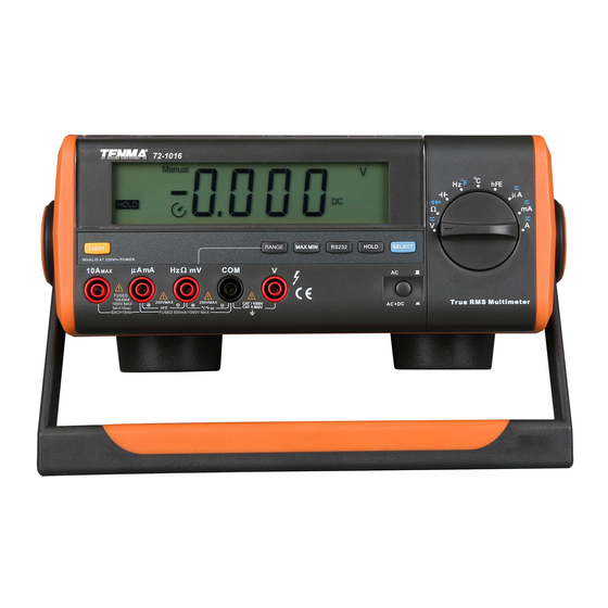
Model 72-1016: OPERATING MANUAL The Meter Structure (see figure 1) (Figure 1) 1. LCD Display 2. Rotary Switch 3. Input Terminals 4. Functional Buttons This Manual: http://www.manuallib.com/file/2587080... -
Page 13: Rotary Switch
Model 72-1016: OPERATING MANUAL Rotary Switch Below table indicated for information about the rotary switch positions: Rotary Switch Position Function AC and DC voltage measurement :Continuity test. :Diode test. :Resistance measurement. Capacitance test :Frequency measurement. :Temperature in Fahrenheit Temperature in celsius Transistor test AC or DC current measurement range from 0.1uA to 5999uA. -
Page 14: Functional Buttons
Model 72-1016: OPERATING MANUAL Functional Buttons Below table indicated for information about the functional button operations. Button Operation Performed POWER Turn the power on and off. LIGHT Turn the display backlight on and off. SELECT Switches between AC and DC measurement. -
Page 15: Display Symbols
Model 72-1016: OPERATING MANUAL Display Symbols (see figure 2) 10 1 5.6.7 Auto Range Manual C umVA AC+DC Trus RMS Trms RS232 DC munF HOLD Mk Hz (Figure 2) This Manual: http://www.manuallib.com/file/2587080... - Page 16 Model 72-1016: OPERATING MANUAL Number Meaning Symbol True RMS Indicator for true rms value. HOLD Data hold is active. Sleep Mode feature is enabled. Indicates negative reading. Indicator for AC voltage or current. Indicator for DC voltage or current AC+DC Indicator for AC+DC measurement The input value is too large for the selected range.
- Page 17 Model 72-1016: OPERATING MANUAL Number Meaning Symbol V, mV V : Volts. The unit of voltage. mV: Millivolt.1 x 10 or 0.001 volts. F, mF, F : Farad.The unit of capacitance. µF,nF mF: Millifarad.1 x 10 or 0.001 farads µF : Microfarad.1x10 or 0.000001 farads.
- Page 18 Model 72-1016: OPERATING MANUAL Number Meaning Symbol AutoRange Indicator of Auto or manual range Manual Display of maximum or minimum value. RS232 Data output is in progress. The battery is low. Warning: To avoid false readings, which could lead to possible electric shock or personal injury, replace the battery as soon as the battery indicator appears.
-
Page 19: Measurement Operation
Model 72-1016: OPERATING MANUAL Measurement Operation A. DC or AC Voltage Measurement (See figure 3) Warning To avoid personal injury, or damage to the Meter from electric shock, please do not attempt to measure voltages higher than 1000V although readings may be obtained. - Page 20 Model 72-1016: OPERATING MANUAL 4. Press AC/AC+DC button to measure AC+DC voltage’s true RMS. Note In each range, the Meter has an input impedance of except 600mV range has 3000M . This loading effect can cause measurement errors in high impedance circuits.
-
Page 21: Dc Or Ac Current Measurement
Model 72-1016: OPERATING MANUAL B. DC or AC Current Measurement (See figure 4) Warning Before connecting the meter in series with the circuit under test, be sure power to the circuit is off to avoid the possibility of arcing. If the fuse burns out during measurement, the Meter may be damaged and there is risk of personal injury to the operator. - Page 22 Model 72-1016: OPERATING MANUAL Note If the value of current to be measured is unknown, use the maximum measurement position, and reduce the range step by step until a satisfactory reading is obtained. For safety sake, each measurement time of high current (>5A) should be less than 10 seconds and...
-
Page 23: Measuring Resistance
Model 72-1016: OPERATING MANUAL C. Measuring Resistance (see figure 5) Warning To avoid damage to the Meter or to the devices under test, disconnect circuit power and discharge all the high-voltage capacitors before measuring resistance. To avoid possible injury, please do not attempt to input voltages higher than 60V DC or 30V AC. - Page 24 Model 72-1016: OPERATING MANUAL Note When resistance measurement has been completed, When measuring low resistances, the test leads and disconnect the connection between the test leads and the circuit under test, and remove the test leads from internal wiring will add approximately 0.2 ~ 0.5...
-
Page 25: Testing Continuity
Model 72-1016: OPERATING MANUAL D. Testing Continuity (See figure 6) Warning To avoid damage to the Meter or to the devices under test, disconnect circuit power and discharge all the high-voltage capacitors before testing for continuity. To avoid personal injury, please do not attempt to input voltages higher than 60V DC or 30V AC. - Page 26 Model 72-1016: OPERATING MANUAL Note In continuity mode, the resistance range is 600 , and the open circuit voltage is approximately 1.2V. When continuity testing has been completed, disconnect the connection between the test leads and the circuit under test, and remove the test leads from the input terminals of the Meter.
-
Page 27: Testing Diodes
Model 72-1016: OPERATING MANUAL E. Testing Diodes (See figure 7) Warning To avoid possible damage to the Meter and to the device under test, disconnect circuit power and discharge all high-voltage capacitors before testing diodes. To avoid personal injury, please do not attempt to input voltages higher than 60V DC or 30V AC. - Page 28 Model 72-1016: OPERATING MANUAL To test a diode out of a circuit, connect the Meter as follows: When diode testing is completed, disconnect the test Insert the red test lead into terminal and the black leads from the device under test, and remove the test lead into the COM terminal.
-
Page 29: Capacitance Measurement
Model 72-1016: OPERATING MANUAL F. Capacitance Measurement (See figure 8) Warning To avoid damage to the Meter or to the equipment under test, disconnect circuit power and discharge all high-voltage capacitors before measuring capacitance. Use the DC Voltage function to confirm that the capacitor is discharged. - Page 30 Model 72-1016: OPERATING MANUAL Note When capacitance measurement has been completed, disconnect the test leads from the device The Meter displays a fixed value which is the under test and remove the leads from the input distributed capacitor’s value of the inside Meter. To terminals of the meter.
-
Page 31: Frequency Measurement
Model 72-1016: OPERATING MANUAL G. Frequency Measurement (see figure 9) Warning To avoid the risk of personal injury, do not attempt to measure frequency with voltage higher than 30V RMS. To measure frequency, connect the Meter as follows: Insert the red test lead into the Hz terminal and the black test lead into the COM terminal. - Page 32 Model 72-1016: OPERATING MANUAL Note When making frequency measurements, the measured signal "a", must fall within the following voltage level: When 10Hz ~ 1MHz :150mV 30V rms When > 1MHz~ 10MHz :300mV 30V rms When > 10MHz~ 50MHz :600mV 30V rms When >...
-
Page 33: Temperature Measurement
Model 72-1016: OPERATING MANUAL H. Temperature Measurement (see figure 10) To measure temperature, connect the Meter as follows: Set the rotary switch to C to measure degree celsius temperature or Hz F and press SELECT button to select F measurement mode to measure Fahrenheit. - Page 34 Model 72-1016: OPERATING MANUAL Note When temperature measurement has been completed, disconnect the connection between the The testing environment must between 18 C to 28 temperature probe, multi-purpose socket and the to ensure accuracy especially when measuring low circuit under test, and remove the temperature probe temperature.
-
Page 35: Measuring Transistor
Model 72-1016: OPERATING MANUAL I. Measuring Transistor (see figure 11) To measure transistor, connect the Meter as follows: Insert the multi-purpose socket into the µAmA and Hz input terminal. Set the rotary switch to hFE. Insert the NPN or PNP type transistor to be tested into the corresponding input terminals of the multi- purpose socket. -
Page 36: Operation Of Hold Mode
Model 72-1016: OPERATING MANUAL Operation of Hold Mode The SELECT Button Some positions of the rotary selector have more than Warning one function. This button is used for selecting the To avoid possibility of electric shock, do not use Hold second function. -
Page 37: Turning On The Display Backlight
Model 72-1016: OPERATING MANUAL Turning on the Display Backlight The RANGE Button Press RANGE to enter the manual ranging mode. Warning Press and hold RANGE for over 1 second to return In order to avoid the hazard arising from mistaken to autoranging. -
Page 38: The Max Min Button
Model 72-1016: OPERATING MANUAL The MAX MIN Button POWER INPUT Switch It is used to select AC 220V/50Hz or DC 6pcs of 1.5V MAX MIN recording mode captures and stores the battery (R14) to power on the Meter. It is located at the maximum and minimum input value detected. -
Page 39: Sleep Mode
Model 72-1016: OPERATING MANUAL Sleep Mode RS232 Button Press RS232 button to enter or exit data output mode. The meter will automatically enter the sleep mode after In RS232C serial port data output mode, the Hold and approximately 10 minutes of inactivity, to preserve Max Min mode cannot output to the computer, the battery life. -
Page 40: General Specifications
Model 72-1016: OPERATING MANUAL General Specifications Relative Humidity: 75% @ 0 C - 30 C below; 50% @ 30 - 40 Maximum Voltage between any Terminals and Altitude: Grounding: Operating: 2000 m. Refer to different range input protection voltage. Storage : 10000 m. -
Page 41: Accuracy Specifications
Model 72-1016: OPERATING MANUAL Accuracy Specifications Accuracy: (a% reading + b digits),guarantee for 1 year. Operating temperature: 23 Relative humidity: not more than 75% RH. Temperature coefficient: 0.1 x (specified accuracy)/1 None: Under the influence of Radiated, Radio-Frequency Electromagnetic Field phenomenon, the captioned model may malfunction and can self-recover after the test. -
Page 42: Ac Voltage
Model 72-1016: OPERATING MANUAL B. AC Voltage Range Resolution Accuracy Overload Protection 40Hz-50kHz: (0.6%+5) 600mV 0.1mV >50kHZ-100kHz: (1%+5) 40Hz-1kHz: (0.6%+5) >1kHz-10kHz: (1.0%+5) 0.001V >10kHz-100kHz: (3%+5) 40Hz-1kHz: (0.6%+5) 1000V >1kHz-10kHz: (1.5%+5) 0.01V >10kHz-20kHz: (3%+5) >20kHz-100kHz: (8%+5) 40Hz-1kHz: (0.6%+5) 600V 0.1V >1kHz-10kHz: (3.5%+5) 40Hz-1kHz: (1.2%+3) - Page 43 Model 72-1016: OPERATING MANUAL Remarks: Input Impedance: At 600mV range : Around > 3000M At all other ranges: Around 10M Displays: True RMS (applicable to the range of 10%~95%) At 1000V range: AC peak factor 1.5. All other ranges: AC peak factor 3.0.
-
Page 44: Dc Current
Model 72-1016: OPERATING MANUAL C. DC Current Range Resolution Accuracy Overload Protection 600µA 0.1µA Fuse 500mA, 250V, 6000µA 1µA (0.5%+3) fast type, φ5x20mm. 60mA 0.01mA 600mA 0.1mA (0.8%+3) Fuse 10A, 250V, 10mA (1.2%+3) fast type, φ5x20mm. Remarks: 5A range: Continuous measurement is allowed. -
Page 45: Ac Current
Model 72-1016: OPERATING MANUAL D. AC Current Range Resolution Accuracy Overload Protection 600µA 0.1µA 40Hz~10kHz: (1.0%+5) 6000µA 1µA Fuse 500mA, 250V, fast >10kHz~15kHz: (2%+5) 60mA 0.01mA type, 5x20mm. 40Hz~10kHz: (1%+5) 600mA 0.1mA >10kHz~15kHz: (3%+5) Fuse 10A,250V, 40Hz~5kHz: (2.0%+6) 10mA fast type, 5x20mm. -
Page 46: Resistance
Model 72-1016: OPERATING MANUAL E. Resistance Range Resolution Accuracy Overload Protection (0.8%+3) + test lead short circuit resistance value 0.001k 250V rms (0.5%+2) 0.01k 600k 0.1k (0.8%+2) 0.001M (1.2%+3) 0.01M This Manual: http://www.manuallib.com/file/2587080... -
Page 47: Continuity Test
Model 72-1016: OPERATING MANUAL F. Continuity Test Range Resolution Overload Protection Remarks Open circuit voltage approximate -1.2V. When circuit disconnected with resistance value 250V rms > 30 , buzzer does not beep. When circuit is in good connection with resistance value buzzer beeps continuously. -
Page 48: Capacitance
Model 72-1016: OPERATING MANUAL H. Capacitance Range Resolution Accuracy Overload Protection 0.001nF (2.5%+5) 60nF 0.01nF 600nF 0.1nF 250V rms (2%+5) 6µF 0.001µF 60µF 0.01µF (3%+4) 600µF 0.1µF (5%+4) 0.001mF Remarks: At 6nF, 60nF and 600nF Range: reading must subtract the test lead open circuit capacitance value. -
Page 49: Frequency
Model 72-1016: OPERATING MANUAL I. Frequency Range Resolution Accuracy Overload Protection 6kHz 0.001kHz 60kHz 0.01kHz (0.1%+3) 250V rms 600kHz 0.1kHz 6MHz 0.001MHz 60MHz 0.01MHz Remarks: Input scope (a): (DC electric level is zero) When 10Hz ~ 1MHz : 150mV 30V rms When >... -
Page 50: Temperature
Model 72-1016: OPERATING MANUAL J. Temperature Range Resolution Accuracy Overload Protection (8%+5) >0 C~400 (1%+7) >400 C~1000 (2%+10) 250V rms F~32 (8%+5) >32 F~752 (1.5%+5) >752 F~1832 (2.5%+5) Remarks: The included point contact temperature probe can only be used to measure under 230 C temperature. -
Page 51: Maintenance
Model 72-1016: OPERATING MANUAL Maintenance A. General Service Periodically wipe the case with a damp cloth and This section provides basic maintenance information mild detergent. Do not use abrasives or solvents. including battery and fuse replacement instruction. To clean the terminals with cotton bar with detergent, as dirt or moisture in the terminals can affect readings. -
Page 52: Replacing The Fuses
Model 72-1016: OPERATING MANUAL B. Replacing the Fuses (see figure 12) Warning To avoid electrical shock or arc blast, or personal injury or damage to the Meter, use specified fuses ONLY in accordance with the following procedure. To replace the Meter’s fuse: 1. - Page 53 Model 72-1016: OPERATING MANUAL Fuse 4:It is located at the PCB. Remove the fuse by gently prying one end loose, then take out the fuse from its bracket. Then install the replacement fuse Install ONLY replacement fuses with the identical type and specification as follows and make sure the fuse is fixed firmly in the bracket.
-
Page 54: Replacing The Battery
Model 72-1016: OPERATING MANUAL C. Replacing the Battery (see figure 13) Warning To avoid false readings, which could lead to possible electric shock or personal injury, replace the battery as soon as the battery indicator “ ” appears when using battery to power on the Meter. -
Page 55: Rs232C And Usb Serial Port
RS232C and USB Serial Port System Requirements for Installing the 72-1016 Interface Program To use 72-1016 Interface Program, you need the following hardware and software: An IBM PC or equivalent computer with 80486 or higher processor and 600 x 800 pixel or better monitor. -
Page 56: Rs232C Serial Port
Model 72-1016: OPERATING MANUAL RS232C Serial Port A. Connecting between the Meter and computer (see figure 14) 72-1016 Back Faceplate To COMPUTER (Figure 14) This Manual: http://www.manuallib.com/file/2587080... -
Page 57: Rs232C Port Cable
Model 72-1016: OPERATING MANUAL B. RS232C Port Cable C. Setting of RS232C Serial Ports Default of RS232C serial port for communication is set as: The Meter Computer Baud Rate 19200 D-sub D-sub D-sub Start bit 9 Pin Male 9 Pin Female... -
Page 58: Usb Serial Port
Meter and the computer with the same port. Please refer to the included “Installation Guide & Computer Interface Software” for installing and operating instructions of the 72-1016 Interface (Figure 15) Program.. The Meter is to be supplied from an identical USB port complying with the requirement of Limit Power Source. - Page 59 Model 72-1016: OPERATING MANUAL Copyright 2006 Tenma Test Equipment. All rights reserved. Tenma Test Equipment 405 S. Pioneer Blvd. Springboro,Ohio 45066 www.tenma.com This Manual: http://www.manuallib.com/file/2587080...
Need help?
Do you have a question about the 72-1016 and is the answer not in the manual?
Questions and answers