Table of Contents
Advertisement
Quick Links
Advertisement
Table of Contents

Subscribe to Our Youtube Channel
Related Manuals for Tenma 72-8720


Summary of Contents for Tenma 72-8720
- Page 1 Model 72-8720: OPERATING MANUAL Model 72-8720 OPERATING MANUAL...
-
Page 2: Table Of Contents
Model 72-8720: OPERATING MANUAL Table of Contents Chapter Title Page Before You Start Overview Unpacking Inspection Safety Information Rules For Safe Operation International Electrical Symbols Getting Acquainted Turning the Meter On Battery Considerations Automatic Power Off Automatic Backlight Off Low Battery Indication... - Page 3 Model 72-8720: OPERATING MANUAL Table of Contents Chapter Title Page C.Measuring DC Millivoltage D.Measuring Currents E.Measuring Resistance F.Testing for Continuity G.Testing Diodes H.Measuring Capacitance I. Measuring Frequency / Duty Cycle J.Measuring Temperature K.4~20mA loop current as % readout Using Stores, Recall and Send Features...
- Page 4 Model 72-8720: OPERATING MANUAL Table of Contents Chapter Title Page Specifications Safety and Compliances Physical Specifications General Specifications Feature Summary Basic Specifications Detailed Accuracy Specifications A. DC Voltage B. AC Voltage C. DC Current D. AC Current E. Resistance F. Continuity Test...
- Page 5 Model 72-8720: OPERATING MANUAL List of Tables Table Title Page Unpacking Inspection International Electrical Symbols Rotary Switch Selections Functional Buttons Functions Vs Displays Display Features Setup Selections...
- Page 6 Model 72-8720: OPERATING MANUAL List of Tables Table Title Page Meter Structure Display Features DC Voltage Measurement AC Voltage Measurement DC Millivoltage Measurement DCµA Currents Measurement ACµA Currents Measurement DCmA Currents Measurement ACmA Currents Measurement DCA Currents Measurement ACA Currents Measurement...
-
Page 7: Before You Start
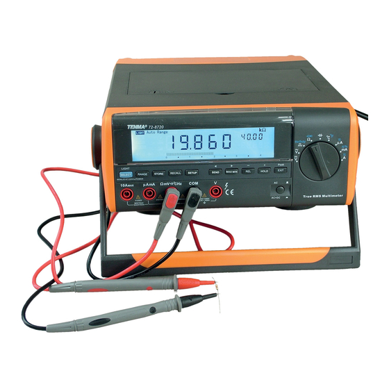
To avoid electric shock or personal injury, read the Safety Information and Rules for Safe Operation carefully before using the Meter. Bench Type Digital Multimeter 72-8720 (hereafter referred to as the Meter) is a 40000 counts and 4 3/4 digits with steady operations, fashionable structure and auto ranging instrument. -
Page 8: Unpacking Inspection
Model 72-8720: OPERATING MANUAL Unpacking Inspection Open the package case and take out the Meter . Check the items shown on Table 1-1 carefully to see any missing or damaged part: Table 1-1. Unpacking Inspection Item Description English Operating Manual... -
Page 9: Safety Information
Model 72-8720: OPERATING MANUAL A Note identifies the information that user should pay Safety Information attention to. This Meter complies with the standards IEC61010 safety International electrical symbols used on the Meter and measurement requirement: in pollution degree 2, in this Operating Manual are explained on page 8. - Page 10 Model 72-8720: OPERATING MANUAL When using the test leads, keep your fingers terminals or between any terminal and grounding. behind the finger guards. The rotary switch should be placed in the right Disconnect circuit power and discharge all high- position and no any changeover of range shall...
-
Page 11: International Electrical Symbols
Model 72-8720: OPERATING MANUAL and accident. International Electrical Symbols The Meter is suitable for indoor use. Symbols used on the Meter and in this manual are When under battery operated situation, turn the explained in Table1-2. Meter off when it is not in use and take out the battery when not using for a long time. -
Page 12: Getting Acquainted
Model 72-8720: OPERATING MANUAL Chapter 2 Getting Acquainted Turning the Meter On The automatic power off is preset to 10 minutes. From To turn the Meter on, switch on the on-ff switch at the the Setup menu (see Chapter 5), you could specify a back of the Meter. -
Page 13: Low Battery Indication
Model 72-8720: OPERATING MANUAL Under AC operated situation, the backlight is always on, cannot turn off. Low Battery Indication A constant battery icon ( ) in the middle left area of the display notifies you that the batteries are low and should be replaced. -
Page 14: Rotary Switch
Model 72-8720: OPERATING MANUAL Rotary Switch Turn the Meter on by selecting any measurement function. The Meter presents a standard display for that function. The display may also be influenced by some of the choices made in Setup. Use the blue SELECT button to select any rotary switch alternate function (labeled in blue letters). -
Page 15: Dc Voltage Measurement
Model 72-8720: OPERATING MANUAL The Table 2-1 described each rotary switch position Table 2-1. Rotary Switch Selections Rotary Switch Rotary Switch Function Blue SELECT Function Position DC voltage measurement None AC voltage measurement None DC millivoltage measurement lFrequency measurements Hz Duty... -
Page 16: Functional Buttons
Model 72-8720: OPERATING MANUAL Functional Buttons The buttons activate features that augment the function selected with the rotary switch. The buttons are shown in Table 2-2. Table 2-2. Functional Buttons Button Description Access Method SELECT feature: Press the button once. - Page 17 Model 72-8720: OPERATING MANUAL Table 2-2. Functional Buttons Button Description Access Method Press to output the data, AUTO mode switch off. The primary Press the button once display shows SEND. Press EXIT to exit. Setup feature: Press the button In Setup, press to select OFF at the selection of HIGH and once after entering Setup mode.
- Page 18 Model 72-8720: OPERATING MANUAL Table 2-2. Functional Buttons Button Description Access Method In Setup, each press to decrement an Option. Press the button once after In Recall, each press to go back to the previous stored reading. entering Setup or Recall or Store In Store, each press to decrease a second on the storing mode.
-
Page 19: The Meter Functions Vs Displays
Model 72-8720: OPERATING MANUAL The Meter Functions Vs Displays Table 2-3 shows the cross reference of function and display: Table 2-3 Functions Vs Displays Function Primary Display Lower Right Secondary Upper Right Secondary Display Display The tested DC voltage value... - Page 20 Model 72-8720: OPERATING MANUAL Table 2-3 Functions Vs Displays Function Primary Display Lower Right Secondary Upper Right Secondary Display Display ACmA The tested ACmA value The tested frequency value: Full range: 400, 4000 40.00kHz~100.0kHz The tested DC current value No display...
-
Page 21: Selecting The Range
Model 72-8720: OPERATING MANUAL Selecting the Range Press RANGE to enter manual ranging mode and select Figure 2-2. Display Features a fixed range. Auto ranging (AUT O lighted in the display) always comes on initially when you select a new function. In... - Page 22 Model 72-8720: OPERATING MANUAL Table 2-4. Display Features Symbol Meaning Maximum reading displayed. Minimum reading displayed The sequence of the reading. Degrees Celsius (default) or Fahrenheit. µ H: Hour H mS µ : Micro m: Minutes (Milli) S: Second Indicates negative reading The battery is low.
- Page 23 Model 72-8720: OPERATING MANUAL Table 2-4. Display Features Symbol Meaning Ω : Ohm. The unit of resistance. k Ω : Kilohm. 1x10 or 1000 ohms Ω, kΩ, MΩ M Ω : Megaohm. 1x10 or 1,000,000 ohms Hz : Hertz. The unit of frequency in cycles/second.
-
Page 24: Continuity Test
Model 72-8720: OPERATING MANUAL Table 2-4. Display Features Symbol Meaning Continuity test Data store is on Data recall is on ∆ The relative mode is on to display the present value minus the stored value. The indicator for the lowest setup limit. -
Page 25: Analogue Bar Graph
Model 72-8720: OPERATING MANUAL Analogue Bar Graph MAX MIN mode can only be used under MANUAL The bar graph provides an analogue indication of the ranging mode. Under frequency and duty cycle measured input. For most measurement functions, the measurement mode, MAX MIN mode is invalid. -
Page 26: Making Measurements
Model 72-8720: OPERATING MANUAL Chapter 3 Making Measurement Introduction Warning Chapter 3 explains how to make measurements. Most To avoid harms to you or damages to the Meter measurement functions can be selected by using the from electric shock, please do not attempt to rotary switch. - Page 27 Model 72-8720: OPERATING MANUAL Note When measuring , the Meter acts around a 10M Ω input impedance in parallel with the circuit. This loading effect can cause measurement errors in high impedance circuits. In most cases, the error high impedance circuits. In most cases, the error is negligible (0.1% or less) if the circuit impedance...
-
Page 28: B.measuring Ac Voltage
Model 72-8720: OPERATING MANUAL 1. Insert the red test lead into the V terminal and the B. Measuring AC Voltage black test lead into the COM terminal. 2. Set the rotary switch to 3. Connect the test leads across with the object being measured. -
Page 29: C.measuring Dc Millivoltage
Model 72-8720: OPERATING MANUAL To measure DC Millivoltage Measurement, set up the C. Measuring DC Millivoltage Meter as Figure 3-3 and do the following: 1. Insert the red test lead into the V terminal and the black test lead into the COM terminal. -
Page 30: D.measuring Currents
Model 72-8720: OPERATING MANUAL D. Measuring Currents To avoid possible damage to the Meter or to the equipment under test, check the Meterís fuses before measuring current. Use proper terminals, function, and range for the measurement. Never place the testing leads in parallel with any circuit or component when the leads are plugged into the current terminals. - Page 31 Model 72-8720: OPERATING MANUAL µ To measure AC A current, set up the Meter as Figure 3-5 and proceed as follows: µ 1.Insert the red test lead into the AmA terminal and black test lead into the COM terminal. µ...
- Page 32 Model 72-8720: OPERATING MANUAL To measure DCmA current, set up the Meter as Figure 3-6 and proceed as follows: µ 1. Insert the red test lead into the AmA terminal and black test lead into the COM terminal. 2. Set the rotary switch to mA .
- Page 33 Model 72-8720: OPERATING MANUAL To measure ACmA current, set up the Meter as Figure 3-7 and proceed as follows: µ 1. Insert the red test lead into the AmA terminal and black test lead into the COM terminal. 2. Set the rotary switch to mA .
- Page 34 Model 72-8720: OPERATING MANUAL To measure DCA current, set up the Meter as Figure 3-8 and proceed as follows: 1. Insert the red test lead into the 10A terminal and black test lead into the COM terminal. 2. Set the rotary switch to A .
- Page 35 Model 72-8720: OPERATING MANUAL 3. Connect the test leads in serial with the object being measured. The measured value shows on the display. It displays the True RMS value . 4. When a ACV function is selected, you can press the AC+DC button to view the AC + DC True RMS value in the primary display.
-
Page 36: E.measuring Resistance
Model 72-8720: OPERATING MANUAL E. Measuring Resistance Warning To avoid harms to you, please do not attempt to input voltage higher than 60V DC or 30V AC. To avoid possible damages to the Meter or to the devices under test, disconnect circuit power and discharge all the high-voltage capacitors before measuring resistance. - Page 37 Model 72-8720: OPERATING MANUAL Note When measuring low resistance, the test leads can add 0.1 to 0.2 of error to resistance measurement. To test the leads, touch the probe tips together and read the resistance of the leads. If necessary, you can press REL ∆...
-
Page 38: F.testing For Continuity
Model 72-8720: OPERATING MANUAL F. Testing for Continuity To test for continuity, set up the Meter as Figure 3-11 and do the following: 1. Insert the red test lead into the terminal and the black test lead into the COM terminal. -
Page 39: G.testing Diodes
Model 72-8720: OPERATING MANUAL G. Testing Diodes Warning To avoid harms to you, please do not attempt to input voltages higher than 60V DC or 30V To avoid damages to the Meter or to the devices under test, disconnect circuit power and discharge all the high-voltage capacitors before testing diodes. - Page 40 Model 72-8720: OPERATING MANUAL on the componentís anode and place the black test the connection between the testing leads and the lead on the componentís cathode. The red test lead circuit under test and remove the test leads away polarity is ì+î while the black test lead polarity is ìó ì.
-
Page 41: H.measuring Capacitance
Model 72-8720: OPERATING MANUAL H. Measuring Capacitance Warning To ensure accuracy, the Meter inside is discharged against the tested capacitor. ---- will be shown on the display when it is under discharging, this process will be quite slow. To avoid damage to the Meter or to the equipment... - Page 42 Model 72-8720: OPERATING MANUAL accuracy. To improve the measurement accuracy of small value capacitors (less than 10nF), press REL ∆ with the test leads open to subtract the residual capacitance of the Meter and leads. 3. It is recommended to use test clip to carry out measurement to reduce the ef f ect of internal distributed capacitor.
-
Page 43: Measuring Frequency / Duty Cycle
Model 72-8720: OPERATING MANUAL I. Measuring Frequency / Duty Cycle To measure frequency and duty cycle, connect the Meter as Figure 3-14 and do the following: 1. Insert the red test lead into the Hz terminal and the black test lead into the COM terminal. -
Page 44: J.measuring Temperature
Model 72-8720: OPERATING MANUAL J. Measuring Temperature 1. Set the rotary switch to , the display shows OL. Short circuit the test leads to show the room temperature. 2. Insert the point contact temperature probe into the Meter as figure 10. -
Page 45: 20Ma Loop Current As % Readout
Model 72-8720: OPERATING MANUAL K. 4~20 mA loop current as % readout Warning To avoid electric shock, please take extra care during measurement. To avoid harms to the Meter and yourself, never input higher than 250V from socket, although readings may be obtained. - Page 46 Model 72-8720: OPERATING MANUAL 3. When the readings obtained is: l < 4mA, the primary display shows LO l 4mA, the primary display shows 0%. Ö. l 20mA, the primary display shows 100% l > 20mA, the primary display shows HI...
-
Page 47: Using Stores, Recall And Send Features
Model 72-8720: OPERATING MANUAL Chapter 4 Using Store, Recall & Send Features - button. The interval can be as high as 255 seconds Introduction or as low as 0 second. Press and hold + or - to Chapter 4 shows you how to use stores, recall and access the quick setting. -
Page 48: Recalling Stored Readings
Model 72-8720: OPERATING MANUAL Recalling Stored Readings Using Send Use the following procedure to recall the stored reading: When using a Send feature, please refer to the Installation Guide of the included CD-ROM. It is possible Press RECALL to recall the stored value and to use RS232 or USB interface cable to connect between RECALL appears to confirm the operation. -
Page 49: Changing The Default Setting
Model 72-8720: OPERATING MANUAL Chapter 5 Changing the Default Setting Introduction The Meter allows you to change the default operating configuration of the Meter by changing setup options made at the factory. These settings are stored and can be changed in the Setup mode using the procedure described in this chapter. - Page 50 Model 72-8720: OPERATING MANUAL Table 5-1. Setup Selections Selection Option Factory Description Default HIGH Max. 40000 Over the upper limits, beeps not continuously. Press to select OFF Press to select the digit you want to edit Max. 40000 Over the lower limits, beeps not continuously.
-
Page 51: Saving Setup Options
Model 72-8720: OPERATING MANUAL Saving Setup Options At each setup Option, store your choice and exit setup by press EXIT, advance to the next Option by press +. To exit the Setup mode without saving the present Option, press Setup. -
Page 52: Maintenance
Model 72-8720: OPERATING MANUAL Chapter 6 Maintenance B. Replacing the Fuses This chapter provides basic maintenance information including battery and fuse replacement instruction. Warning Do not attempt to repair or service your Meter unless you are qualified to do so and have the relevant calibration, performance test, and service information. - Page 53 Model 72-8720: OPERATING MANUAL Place back the fuse cover and the power socket. Warning Place back the compartment and the case top and close the compartment. To avoid electrical shock or arc blast, or personal injury or damage to the Meter, use specified fuses Replacement of the fuses is seldom required.
-
Page 54: C.replacing The Battery
Model 72-8720: OPERATING MANUAL C. Replacing the Battery Warning To avoid false readings, which could lead to possible electric shock or personal injury, replace the battery as soon as the battery indicator " " appears when the Meter is under battery operated situation. -
Page 55: Specifications
Model 72-8720: OPERATING MANUAL Chapter 7 Specifications Safety and Compliances Refer to different range input protection voltage Maximum Voltage between any Terminal and Grounding Certification Compliances IEC 61010 CAT.I 1000V, CAT.II 600V overvoltage and double insulation standard Fused Protection for µ AmA input terminal: 0.5A, 250V, fast type fuse, ø5×20mm... -
Page 56: Physical Specifications
Model 72-8720: OPERATING MANUAL Physical Specifications Display (LCD) Digital: 40000 counts on primary display; updates 2-3 times / second. 4000 counts on secondary display. Analog: 40 segments; updates 10 times / second. Operating Temperature C~40 C (32 F~104 Storage Temperature... -
Page 57: General Specifications
Model 72-8720: OPERATING MANUAL General Specifications Range Auto Polarity Auto Overloading Display OL (except at 4~20mA Loop range which display HI or LO) Battery Deficiency Display Feature Summary Tri Displays Primary: 40,000 counts Left Secondary: 4000 counts. Right Secondary: 4000 counts... -
Page 58: Basic Specifications
Model 72-8720: OPERATING MANUAL Basic Specifications Function Ranges / Description DC Voltage 0 to 1000V AC Voltage, True RMS 0 to 1000V, 100kHz bandwidth Basic Accuracy DC Voltage: 0.025% AC Voltage: 0.4% DC Current 0 to 10A (5~10A for 10 seconds, interval... -
Page 59: Detailed Accuracy Specifications
Model 72-8720: OPERATING MANUAL Detailed Accuracy Specifications Accuracy: ( [% of reading] + [number of least significant digits] ), guar antee for 1 year. Operating temperature: 18 C~28 Relative humidity: 75%RH A. DC Voltage Range Resolution Accuracy Overload Protection Input Impedance (0.025%+5) under... -
Page 60: Ac Voltage
Model 72-8720: OPERATING MANUAL B. AC Voltage (AC+DC measurement is available) Range Resolution Bandwidth Accuracy 45Hz~1kHz (0.4%+30) 0.0001V >1kHz~10kHz (1.5%+30) >10kHz~100kHz (6%+30) 45Hz~1kHz (0.4%+30) 0.001V >1kHz~10kHz (1.5%+30) >10kHz~100kHz (6%+30) 45Hz~1kHz (0.4%+30) 0.01V 400V >1kHz~10kHz (5%+30) >10kHz~100kHz Not Specified 45Hz~1kHz (1%+30) 0.1V... -
Page 61: Dc Current
Model 72-8720: OPERATING MANUAL True rms are valid from 10% of range to 100% of range AC crest factor can be up to 3.0 except 1000V where it is 1.5. A residual reading of 80 digits with test leads shorted, will not affect stated accuracy. -
Page 62: Ac Current
Model 72-8720: OPERATING MANUAL D. AC Current (AC+DC measurement is available) Range Resolution Bandwidth Accuracy Overload Protection 45Hz~1kHz (0.7%+15) 400 µ A 0.01 µ A >1kHz~5kHz (1%+30) 4000 µ A 0.1 µ A 0.5A, 250V, fast type fuse, ø5×20mm >5kHz~10kHz... -
Page 63: Resistance
Model 72-8720: OPERATING MANUAL E. Resistance Range Resolution Accuracy Overload Protection 400 Ω 0.01 Ω (0.3%+40)+test leads open circuit value 4k Ω 0.0001k Ω (0.3%+40) 40k Ω 0.001k Ω 1000V (0.5%+40) 400k Ω 0.01k Ω 4M Ω 0.0001M Ω (1%+40) 40M Ω... -
Page 64: Diode Test
Model 72-8720: OPERATING MANUAL G. Diode Test Range Resolution Overload Protection 1000V 0.0001V Remarks: l Open circuit voltage approximate 2.8V. l A good silicon junction drops between 0.5V and 0.8V. H. Capacitance Range Resolution Accuracy Overload Protection 40nF 0.001nF (1%+20)+ capacitance value of open circuit... -
Page 65: Frequency
Model 72-8720: OPERATING MANUAL I. Frequency Range Resolution Accuracy Overload Protection 40Hz 0.001Hz 400Hz 0.01Hz 4kHz 0.0001kHz 40kHz 0.001kHz (0.01%+8) 1000V 400kHz 0.01kHz 4MHz 0.0001MHz 40MHz 0.001MHz Not Specified 400MHz 0.01MHz Remarks: l Input amplitude ìaî as follows; (DC electric level is zero) When 10Hz~40MHz : 200mV 30Vrms;... -
Page 66: Duty Cycle
Model 72-8720: OPERATING MANUAL J. Duty Cycle Range Resolution Accuracy Overload Protection 100% 0.01% (0.01%+40) 1000V Remarks: l It is valid from 10% of range to 90% of range. l Input amplitude ìaî as follows; (DC electric level is zero) When 10Hz~40MHz : 200mV 30Vrms;... -
Page 67: Fahrenheit
Model 72-8720: OPERATING MANUAL 1-2. Fahrenheit Range Resolution Accuracy Overload Protection (4%+50) F~32 (1.5%+50) 0 . 1 1000V F~752 F~1832 Remarks: l Included is a K-Type (nickel chromium-nickel silicon) point contact temperature probe which could only measure temperature below 230 C. - Page 68 Model 72-8720: OPERATING MANUAL ** END ** This operating manual is subject to change without notice.
- Page 69 Model 72-8720: OPERATING MANUAL © Copyright 2010 T enma. All rights reserved. Manufacturer: Tenma 405 S. Pioneer Blvd, Springboro, Ohio 45066-3001 Phone: 1-888-655-5409 Fax: 1-800-765-6960...
Need help?
Do you have a question about the 72-8720 and is the answer not in the manual?
Questions and answers