Table of Contents
Advertisement
Quick Links
Advertisement
Table of Contents

Related Manuals for Tenma 72-7228


Summary of Contents for Tenma 72-7228
- Page 1 72-7228 Digital Clamp Multimeter P/N: 110401100913...
- Page 2 Model 72-7228 OPERATING MANUAL...
-
Page 3: Table Of Contents
Model 72-7228: OPERATING MANUAL Table of Contents Title Page Overview Inspection Safety Information Rules For Safe Operation International Electrical Symbols The Meter Structure Functional Buttons The Effectiveness of Functional Buttons Display Symbols Measurement Operation A. DC/AC Voltage Measurement B. Measuring Resistance C. - Page 4 Model 72-7228: OPERATING MANUAL Title Page G. DC Current Measurement H. AC Current Measurement Sleep Mode Specifications A. General Specifications B. Environmental Requirements Accuracy Specifications A. DC Voltage B. AC Voltage C. Resistance D. Diode Test E. Continuity Test F. Frequency G.
- Page 5 Model 72-7228: OPERATING MANUAL Title Page I. AC Current Maintenance A. General Service B. Replacing the Battery...
-
Page 6: Overview
To avoid electric shock or personal injury, read the “Safety Information” and “Rules for Safe Operation” carefully before using the Meter. Digital Clamp Multimeter Model 72-7228 (hereafter referred to as “the Meter”) features 3 5/6 digits and a 6666 count display. It uses large scale integrated circuit with double integrated A/D converter as its core and has full range overload protection. -
Page 7: Inspection
Model 72-7228: OPERATING MANUAL Inspection Open the package case and take out the Meter. Carefully check the following items for missing or damaged parts: Item Description Operating manual 1 piece Test Lead 1 pair Carry case 1 piece 9V Battery (NEDA1604A or 6LF22) 1 piece In the event items are missing or damaged, contact your dealer immediately. -
Page 8: Safety Information
Model 72-7228: OPERATING MANUAL Safety Information This Meter complies with the standards IEC61010-1; IEC61010-2-032: in pollution degree 2, overvoltage category (CAT. II 600V, CAT. III 300V) and double insulation. CAT. II: Local level, appliance, PORTABLE EQUIPMENT etc., with smaller transient overvoltages than CAT. -
Page 9: Rules For Safe Operation
Model 72-7228: OPERATING MANUAL Rules For Safe Operation Warning To avoid possible electric shock or personal injury, and to avoid possible damage to the Meter or to the equipment under test, adhere to the following rules: Before using the Meter inspect the case. Do not use the Meter if it is damaged or the case (or part of the case) is removed. - Page 10 Model 72-7228: OPERATING MANUAL the input terminals of the Meter and turn the Meter power off. Ensure the rotary switch is in the correct position prior to measurement. To prevent damage to the meter, range or mode changes should not be made during measurement.
- Page 11 Model 72-7228: OPERATING MANUAL Replace the battery as soon as the battery indicator appears. With a low battery, the Meter might produce false readings that can lead to electric shock and personal injury. When servicing the Meter, use only the same model number or identical electrical specifications replacement parts.
-
Page 12: International Electrical Symbols
Model 72-7228: OPERATING MANUAL International Electrical Symbols AC (Alternating Current) DC (Direct Current) AC or DC Ground Double Insulated Warning. Refer to the Operating Manual Low Battery Continuity Test Diode Danger of High Voltage Conforms to Standards of European Union... -
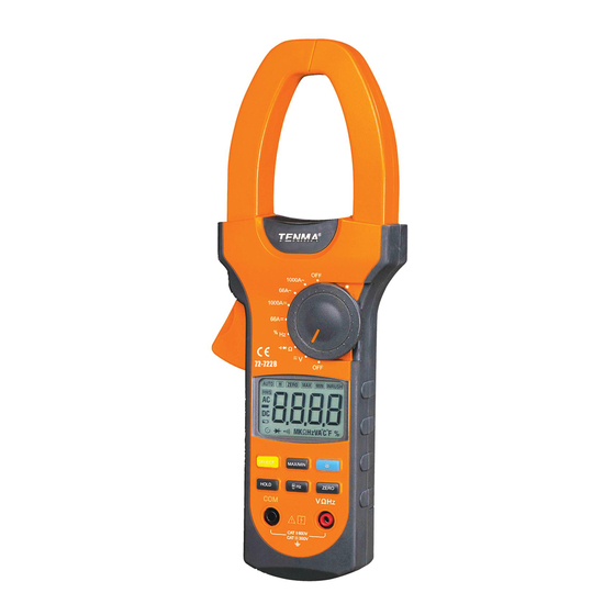
Page 13: The Meter Structure
Model 72-7228: OPERATING MANUAL The Meter Structure (see figure 1) Hand Guards: to protect user’s hand from touching the dangerous area. Trigger: press the lever to open the transformer jaws. When the pressure on the lever is released, the jaws will close. -
Page 14: Functional Buttons
Model 72-7228: OPERATING MANUAL Functional Buttons The following table provides information about the operation of functional buttons. Button Operation Performed Starts recording of maximum and minimum values. MAX/MIN Press to step the display through high (MAX) and low (MIN) readings at any mode. - Page 15 Model 72-7228: OPERATING MANUAL Button Operation Performed HOLD Press HOLD button for 2 seconds when turning on the Meter to display full icon. , press Hz to measure When the Meter is at %Hz, V and A frequency and duty cycle.
- Page 16 Model 72-7228: OPERATING MANUAL Functional Buttons Not every functional buttons may be used on every rotary switch position. The following table describes which buttons may be used on which rotary switch positions. Functional Buttons Rotary Switch Positions SELECT MAX/MIN HOLD...
-
Page 17: Display Symbols
Model 72-7228: OPERATING MANUAL Display Symbols (see figure 2) Figure 2... - Page 18 Model 72-7228: OPERATING MANUAL Number Symbol Meaning INRUSH Indicator for Surge current Minimum reading displayed Maximum reading displayed ZERO Indicator for zeroing Data hold is active The Meter is in the auto range mode in which the AUTO Meter automatically selects the range with the best resolution.
- Page 19 Model 72-7228: OPERATING MANUAL Number Symbol Meaning Sleep mode is on Diode test The continuity buzzer is on : Ohm. The unit of resistance. ,K ,M k :Kilohm. 1x10 or 1000 ohms M :Megohm. 1x10 or 1,000,000 ohms Hz: Hertz. The unit of frequency.
-
Page 20: Measurement Operation
Model 72-7228: OPERATING MANUAL Measurement Operation A. DC/AC Voltage Measurement (see figure 3) Warning To avoid personal injury or damage to the Meter from eletric shock, do not attempt to measure voltages higher than 600V AC/DC, although readings may be obtained. - Page 21 Model 72-7228: OPERATING MANUAL The DC Voltage ranges are: 6.6V, 66V and 600V The AC Voltage ranges are: 6.6V, 66V and 600V To measure DC/AC voltages, connect the Meter as follows: Insert the red test lead into the V Hz terminal and black test lead into the COM terminal.
-
Page 22: Measuring Resistance
Model 72-7228: OPERATING MANUAL B. Measuring Resistance (see figure 4) Warning To avoid damage to the Meter or to the devices under test, disconnect circuit power and discharge all the high-voltage capacitors before measuring resistance. The resistance ranges are: 660 , 6.6k , 66k , 660k , 6.6M... - Page 23 Model 72-7228: OPERATING MANUAL Connect the test leads across with the object being measured. The measured value shows on the display. Note To obtain a more precise reading, you could remove the objects being tested from the circuit when measuring.
-
Page 24: Testing Diodes
Model 72-7228: OPERATING MANUAL C. Testing Diodes (see figure 5) Warning To avoid damage to the Meter or to the devices under test, disconnect circuit power and discharge all the high-voltage capacitors before testing diodes. Use the diode test to check diodes, transistors, and other semiconductor devices. - Page 25 Model 72-7228: OPERATING MANUAL Insert the red test lead into the V Hz terminal and black test lead into the COM terminal. Set the rotary switch to . Press SELECT to switch to measurement mode. For forward voltage drop readings on any semiconductor component, place the red test lead on the component’s anode and place the black test lead on the...
-
Page 26: Testing For Continuity
Model 72-7228: OPERATING MANUAL D. Testing for Continuity (see figure 6) Warning To avoid damage to the Meter or to the devices under test, disconnect circuit power and discharge all the high-voltage capacitors before measuring continuity. To test for continuity, connect the Meter as follows: Insert the red test lead into the V Hz terminal and the black test lead into the COM terminal. - Page 27 Model 72-7228: OPERATING MANUAL a circuit under test is higher than 100 . Note When continuity testing has been completed, disconnect the test leads from the circuit under test and remove the test leads from the input terminals.
-
Page 28: Frequency Measurement
Model 72-7228: OPERATING MANUAL E. Frequency Measurement (see figure 7) Warning Personal injury or damage to the Meter from eletric shock, do not attempt to measure voltages higher than 600V AC/DC, although readings may be obtained. The frequency ranges are: 660Hz, 6.6kHz, 66kHz, 660kHz, 6.6MHz and 66MHz. - Page 29 Model 72-7228: OPERATING MANUAL being measured. The measured value shows on the display. Note When frequency measurement has been completed, disconnect the test leads from the circuit under test and remove the test leads from the input terminals.
-
Page 30: Duty Cycle Measurement
Model 72-7228: OPERATING MANUAL F. Duty Cycle Measurement (see figure 8) Warning Personal injury or damage to the Meter from eletric shock, do not attempt to measure voltages higher than 600V AC/DC, although readings may be obtained. The duty cycle range is: 0.1%~99.9%. - Page 31 Model 72-7228: OPERATING MANUAL Note When duty cycle measurement has been completed,disconnect the test leads from the circuit under test and remove the test leads from the input terminals.
-
Page 32: Dc Current Measurement
Model 72-7228: OPERATING MANUAL G. DC Current Measurement (see figure 9) The measurement ranges of current are: 66A and 1000A To measure current, do the following: Set the rotary switch to 66A or 1000A Hold the Meter firmly and steadily. Internal components are very sensitive to movement or physical shock as this will effect readings. - Page 33 Model 72-7228: OPERATING MANUAL Note If the Meter does not display 00.00 when it is at 66A range, press ZERO to zeroing. After zeroing, it allows 10 digits bouncing reading. While in the 66A range, if the meter does not display 00.00, press ZERO to zero the meter.the meter should display 0, and the ZERO button is inoperative.
-
Page 34: Ac Current Measurement
Model 72-7228: OPERATING MANUAL H. AC Current Measurement (see figure 10) Warning The measurement ranges of current are: 66.00A and 1000A To measure AC current, do the following: Set the rotary switch to 66A or 1000A Hold the Meter firmly and steadily. Internal components are very sensitive to movement or physical shock as this will effect readings. - Page 35 Model 72-7228: OPERATING MANUAL transformer jaw, The Meter can only measure one conductor at a time. When the measuring current >1A, press Hz button to step through AC current, frequency and duty cycle measurement mode. But the frequency or duty cycle readings obtained from this range is only for reference.
- Page 36 Model 72-7228: OPERATING MANUAL Note When current measurement has been completed, press the button to open the jaw, and remove the conductor away from the transformer jaw of the Meter.
-
Page 37: Sleep Mode
Model 72-7228: OPERATING MANUAL Sleep Mode To preserve battery life, the Meter automatically turns off after 15 minutes of inactivity. The Meter beeps 3 times one minute before entering Sleep Mode and one long beep just before entering Sleep Mode. -
Page 38: Specifications
Model 72-7228: OPERATING MANUAL Specifications A. General Specifications: Maximum Voltage between any Terminals and ground: Refer to different range input protection voltage. Display: 3 5/6 digits LCD display, Maximum display 6666. Polarity: Auto Overloading: Display OL or –OL. Low Battery: Display Sampling: 3 times per second. -
Page 39: Environmental Requirements
Model 72-7228: OPERATING MANUAL Battery Life: typically 150 hours (alkaline battery) Dimensions: 285.3mm x 105mm x 44.5mm Weight: Approximate 533g (battery included) B. Environmental Requirements The Meter is suitable for indoor use. Altitude: Operating: 2000m Storage: 10000m Safety/ Compliances: IEC61010-1; IEC61010-2-032. CAT.II 600V, CAT.III 300V over voltage and double insulation standard, pollution degree 2. -
Page 40: Accuracy Specifications
Model 72-7228: OPERATING MANUAL Accuracy Specifications Accuracy: (a% reading + b digits), guarantee for 1 year. Operating temperature: 23 Relative humidity: 80%R.H Temperature coefficient: 0.1x(specified accuracy)/1 A. DC Voltage Range Resolution Accuracy Overload protection 6.600V (0.8%+1) 66.00V 10mV 600V DC/AC 600.0V... -
Page 41: Ac Voltage
Model 72-7228: OPERATING MANUAL B. AC Voltage Range Resolution Accuracy Overload protection 6.600V (1.2%+5) 66.00V 10mV 600V DC/AC 600.0V 100mV Remarks: Input Impedance: 10M Frequency Response: 40Hz~400Hz Change to AC: Combine AC and True RMS response method. Input sine wave to adjust. Non sine wave signals must be adjusted based on the following data: Peak factor: 1.4~2.0, add 1.0% to the stated accuracy... -
Page 42: Resistance
Model 72-7228: OPERATING MANUAL C. Resistance Range Resolution Accuracy Overload protection 660.0Ω 0.1Ω (1.2%+2) 6.600kΩ 1Ω 66.00kΩ 10Ω (1%+2) 250VAC 660.0kΩ 100Ω 6.600MΩ 1kΩ (1.2%+2) 66.00MΩ 10kΩ (1.5%+2) D. Diode Test Range Resolution Accuracy Overload protection 0.5V~0.8V (Open circuit voltage 250VAC approx. -
Page 43: Continuity Test
Model 72-7228: OPERATING MANUAL E. Continuity Test Range Resolution Accuracy Overload protection Around 30Ω,the buzzer will sound. 250VAC (Open circuit voltage approx. –1.2V) Remark: The buzzer may or may not sound when the resistance of a circuit under test is between 30Ω~100Ω. -
Page 44: Frequency
Model 72-7228: OPERATING MANUAL F. Frequency Range Resolution Accuracy Overload protection 660.0Hz 0.1Hz 6.600kHz 0.001kHz 66.00kHz 0.01kHz (0.1%+3) 250VAC 660.0kHz 0.1kHz 6.600MHz 0.001MHz 66.00MHz 0.01MHz Remarks: Input Sensitivity (a) as follows: When a 10Hz: the Meter does not respond When 10Hz < a 100kHz: 300mV rms... -
Page 45: Duty Cycle
Model 72-7228: OPERATING MANUAL G. Duty Cycle Range Resolution Accuracy Overload protection 0.1%~99.9% 0.1% For reference only 250VAC H. DC Current Range Resolution Accuracy Overload protection 66.00A 0.01A (1.5%+12) 1000A DC/AC 1000A (1.5%+8) Warning The operating temperature must be 0 ~ 40 when measuring current. - Page 46 Model 72-7228: OPERATING MANUAL Remarks: If the current flow is from the back of the meter to the front, the reading will be positive. The opposite direction will provide a negative reading. The internal components are very sensitive to magnetic fields and physical force and shock.
- Page 47 Model 72-7228: OPERATING MANUAL I. AC Current Range Resolution Accuracy Frequency Overload protection Response 66.00A 0.01A (2%+12) 50Hz ~ 60Hz 1000A DC/AC 1000A (2%+8) Warning The operating temperature must be 0 when measuring current. Remarks: Change to AC: Combine AC and True RMS response method. Input sine wave to adjust.
- Page 48 Model 72-7228: OPERATING MANUAL MAINTENANCE This section provides basic maintenance information including battery replacement instruction. Warning Do not attempt to repair or service your Meter unless you are qualified to do so and have the relevant calibration, performance test, and service information.
- Page 49 Model 72-7228: OPERATING MANUAL B. Replacing the Battery (see figure 12) Warning To avoid false readings, which could lead to possible electric shock or personal injury, replace the battery as soon as the battery indicator “ ” appears. Make sure the transformer jaw and the...
- Page 50 Model 72-7228: OPERATING MANUAL To replace the battery: 1. Turn the Meter off and remove all the connections from the input terminals 2. Turn the Meter’s front case down. 3. Remove the screw from the battery compartment, and separate the battery compartment from the case bottom.
- Page 51 Model 72-7228: OPERATING MANUAL * END * This operating manual is subject to change without notice.
- Page 52 Model 72-7228: OPERATING MANUAL Copyright 2007 Tenma Test Equipment. All rights reserved. Tenma Test Equipment 405 S. Pioneer Blvd. Springboro,Ohio 45066 www.tenma.com...
Need help?
Do you have a question about the 72-7228 and is the answer not in the manual?
Questions and answers