Table of Contents
Advertisement
Advertisement
Table of Contents

Related Manuals for Tenma 72-7224


Summary of Contents for Tenma 72-7224
- Page 1 72-7224 / 72-7226 Digital Clamp Multimeters...
-
Page 2: Table Of Contents
Model 72-7224 / 72-7226: OPERATING MANUAL Table of Contents Title Page Overview Inspection Safety Information Rules For Safe Operation International Electrical Symbols The Meter Structure Rotary Switch Function Buttons Button Use Display Symbols Measurement Operation A. DC/AC Voltage Measurement B. Measuring Resistance C. - Page 3 Model 72-7224 / 72-7226: OPERATING MANUAL Title Page Sleep Mode Specifications A. General Specifications B. Environmental Requirements Accuracy Specifications A. DC Voltage B. AC Voltage C. Resistance D. Diode Test E. Continuity Test F. Frequency G. Duty Cycle H. DC Current I.
-
Page 4: Overview
To avoid electric shock or personal injury, read the “Safety Information” and “Rules for Safe Operation” carefully before using the Meter. Digital Clamp Multimeter Models 72-7224 and 72-7226 (hereafter referred to as “the Meter”) are 3 3/4 digits with precise operation, fashionable structure and highly reliable measuring instrument. -
Page 5: Inspection
Model 72-7224 / 72-7226: OPERATING MANUAL Inspection Open the package case and take out the Meter. Check the following items carefully to see if any items are missing or damaged. Item Description English Operating Manual 1 piece Test Lead 1 pair... -
Page 6: Safety Information
Model 72-7224 / 72-7226: OPERATING MANUAL Safety Information This Meter complies with the standards IEC61010: in pollution degree 2, overvoltage category (CAT. II 600V, CAT. III 300V) and double insulation. CAT. II: Local level, appliance, PORTABLE EQUIPMENT etc., with smaller transient overvoltages than CAT. -
Page 7: Rules For Safe Operation
Model 72-7224 / 72-7226: OPERATING MANUAL Rules For Safe Operation Warning To avoid possible electric shock or personal injury, and to avoid possible damage to the Meter or to the equipment under test, adhere to the following rules: Before using the Meter inspect the case. Do not use the Meter if it is damaged or the case (or part of the case) is removed. - Page 8 Model 72-7224 / 72-7226: OPERATING MANUAL The rotary switch should be placed in the correct position and no change of range made during measurement, to prevent damage to the Meter. Do not carry out the measurement when the Meter’s back case and battery compartment are not closed to avoid electric shock.
- Page 9 Model 72-7224 / 72-7226: OPERATING MANUAL The internal circuit of the Meter shall not be altered at will to avoid damage of the Meter and any accident. Soft cloth and mild detergent should be used to clean the surface of the Meter when servicing.
-
Page 10: International Electrical Symbols
Model 72-7224 / 72-7226: OPERATING MANUAL International Electrical Symbols AC (Alternating Current) DC (Direct Current) AC or DC Ground Double Insulated Warning. Refer to the Operating Manual Low Battery Continuity Test Diode Fuse Application around and removal from HAZARDOUS LIVE conductors is permitted. -
Page 11: The Meter Structure
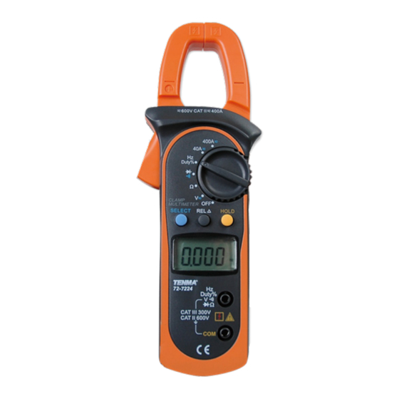
Model 72-7224 / 72-7226: OPERATING MANUAL The Meter Structure (see figure 1) Input Terminals LCD Display Function Buttons Rotary Switch Trigger: press the lever to open the transformer jaws. When the pressure on the lever is released, the jaws will close. -
Page 12: Rotary Switch
Model 72-7224 / 72-7226: OPERATING MANUAL Rotary Switch The following table provides information regarding the Rotary Switch positions. Rotary Switch Position Function Power is turned off AC or DC voltage measurement Resistance measurement : Diode test : Continuity test Hz / Duty%... -
Page 13: Function Buttons
Model 72-7224 / 72-7226: OPERATING MANUAL Function Buttons The following table provides information regarding the rotary switch positions. Button Operation Performed Press HOLD to enter the Hold mode in any mode, the Meter will HOLD beep to confirm. Press HOLD again to exit the Hold mode, the Meter will again beep to confirm. - Page 14 Model 72-7224 / 72-7226: OPERATING MANUAL Button Operation Performed SELECT Press SELECT button to select the alternate functions marked in blue colour on the Meter’s faceplate including , and 400 If the meter enters sleep mode, press and hold the SELECT button...
-
Page 15: Button Use
Model 72-7224 / 72-7226: OPERATING MANUAL Function Button Use Not every function button is used in every rotary switch position. The table below indicates which button can be used in which switch position. Function Buttons Rotary Switch Positions SELECT HOLD... -
Page 16: Display Symbols
Model 72-7224 / 72-7226: OPERATING MANUAL Display Symbols (see figure 2) (figure 2) - Page 17 Model 72-7224 / 72-7226: OPERATING MANUAL Number Symbol Meaning Indicator for AC voltage or current Indicator for DC voltage The battery is low. Warning: To avoid false readings, which could lead to possible electric shock or personal injury, replace the battery as soon as the battery indicator appears.
- Page 18 Model 72-7224 / 72-7226: OPERATING MANUAL Number Symbol Meaning ,k ,M : Ohm. The unit of resistance. k : Kilohm. 1x10 3 or 1000 ohms M : Megohm. 1x10 6 or 1,000,000 ohms The unit of Frequency Amperes (amps). The unit of current.
-
Page 19: Measurement Operation
Model 72-7224 / 72-7226: OPERATING MANUAL Measurement Operation A. DC/AC Voltage Measurement (see figure 3) Warning To avoid damage to the meter, or risk of personal injury, do not attempt to measure higher than 600V AC/DC, although readings may be obtained. - Page 20 Model 72-7224 / 72-7226: OPERATING MANUAL Set the rotary switch to . DC mesaurement mode and auto ranging is a default. Press SELECT to switch to AC measurement mode or press to switch to manual ranging measurement mode. Connect the test leads across with the object being measured.
-
Page 21: Measuring Resistance
Model 72-7224 / 72-7226: OPERATING MANUAL B. Measuring Resistance (see figure 4) Warning To avoid damage to the Meter or to the devices under test, disconnect circuit power and discharge all the high-voltage capacitors before measuring resistance. The resistance ranges are: 400 , 4k , 40k ,400k ,4M and 40M . - Page 22 Model 72-7224 / 72-7226: OPERATING MANUAL Note For precise reading, the device under test should first be removed from its circuit. When resistance measurement has been completed, disconnect the test leads from the circuit under test, and remove them from the input terminals.
-
Page 23: Testing Diodes
Model 72-7224 / 72-7226: OPERATING MANUAL C. Testing Diodes (see figure 5) Warning To avoid damage to the Meter or to the devices under test, disconnect circuit power and discharge all the high-voltage capacitors before testing diodes. Use the diode test to check diodes, transistors, and other semiconductor devices. - Page 24 Model 72-7224 / 72-7226: OPERATING MANUAL Set the rotary switch to . Diode measurement mode is a default or presss SELECT to select measurement mode. For forward voltage drop readings on any semiconductor component, place the red test lead on the component’s anode and place the black test lead on the component’s cathode.
-
Page 25: Testing For Continuity
Model 72-7224 / 72-7226: OPERATING MANUAL D. Testing for Continuity (see figure 6) Warning To avoid damage to the Meter or to the devices under test, disconnect circuit power and discharge all the high-voltage capacitors before measuring continuity. To test for continuity, connect the Meter as follows:... - Page 26 Model 72-7224 / 72-7226: OPERATING MANUAL Note When continuity testing has been completed, disconnect the test leads from the circuit under test, and remove them from the input terminals.
-
Page 27: Frequency Measurement
Model 72-7224 / 72-7226: OPERATING MANUAL E. Frequency Measurement (see figure 7) Warning To avoid damage to the meter, or risk of personal injury, do not attempt to measure higher than 600V AC/DC, although readings may be obtained. The frequency ranges are:... - Page 28 Model 72-7224 / 72-7226: OPERATING MANUAL Note When frequency measurement has been completed, disconnect the test leads from the circuit under test, and remove them from the input terminals.
-
Page 29: Duty Cycle Measurement
Model 72-7224 / 72-7226: OPERATING MANUAL F. Duty Cycle Measurement (see figure 8) Warning To avoid damage to the meter, or risk of personal injury, do not attempt to measure higher than 600V AC/DC, although readings may be obtained. The duty cycle range is: 0.1%~99.9%. - Page 30 Model 72-7224 / 72-7226: OPERATING MANUAL Note When duty cycle measurement has been completed, disconnect the test leads from the circuit under test, and remove them from the input terminals.
-
Page 31: Dc/Ac Current Measurement
Model 72-7224 / 72-7226: OPERATING MANUAL G. DC/AC Current Measurement (see figure 9) The measuremnet ranges of current are: 40.00 and 400.0 To measure current, do the following: 400A Set the rotary switch to 40 or 400 . DC measuremnet mode is a default. Press SELECT to switch between DC and AC measurement mode. - Page 32 Model 72-7224 / 72-7226: OPERATING MANUAL Note Press to subtract a stored value from the present measurement value and display a result. When current measurement has been completed, disconnect the connection between the conductor under test and the jaw, press the lever to open the...
-
Page 33: Sleep Mode
Model 72-7224 / 72-7226: OPERATING MANUAL Sleep Mode To preserve battery life, the Meter automatically turns off after 15 minutes of inactivity. The Meter can be activated by pressing any button or changing the position of the rotary switch. Approximately one minute before entering sleep mode, the buzzer will beep five times. -
Page 34: Specifications
Model 72-7224 / 72-7226: OPERATING MANUAL Specifications A. General Specifications: Maximum Voltage between any Terminals and ground: Refer to different range input protection voltage. Display: 3 3/4 digits LCD display, Maximum display 3999 Polarity: Automatically display. Overload: Display OL or –OL Low battery: Display Measurement Speed: Updates 3 times/second. -
Page 35: Environmental Requirements
Model 72-7224 / 72-7226: OPERATING MANUAL Battery Life: typically 150hours (alkaline battery) Sleep Mode (can be disabled) Dimensions (H x W x L): 208mm x 76mm x 30mm. Weight: Approximate 260g (battery included) B. Environmental Requirements The Meter is suitable for indoor use. -
Page 36: Accuracy Specifications
Model 72-7224 / 72-7226: OPERATING MANUAL Accuracy Specifications Accuracy: (a% reading + b digits), guarantee for 1 year. Operating temperature: 23ºC 5ºC Relative humidity: 85%R.H Temperature coefficient: 0.1x(specified accuracy)/1ºC A. DC Voltage Range Resolution Accuracy Overload protection 400.0mV 0.1mV (0.8%+3) 4.000V... -
Page 37: Ac Voltage
Model 72-7224 / 72-7226: OPERATING MANUAL B. AC Voltage Range Resolution Accuracy Overload protection 4.000V 40.00V 10mV (1%+5) 600V DC/AC 400.0V 100mV 600V (1.2%+5) Remarks: Input impedance: 10M // less than 100pF Frequency response: 40Hz~400Hz. Change to AC: 72-7224: Change to AC by using average response method. Input sine wave, then adjust the reading until it is same as the effective value. -
Page 38: Resistance
Model 72-7224 / 72-7226: OPERATING MANUAL C. Resistance Range Resolution Accuracy Overload protection 400.0 100m (1.2%+2) 4.000k 600Vp 40.00k (1%+2) 400.0k 4.000M (1.2%+2) 40.00M (1.5%+2) D. Diode Test Range Resolution Accuracy Overload protection Display approximate forward 600Vp voltage drop: 0.5V~0.8V... -
Page 39: Continuity Test
Model 72-7224 / 72-7226: OPERATING MANUAL E. Continuity Test Range Resolution Accuracy Overload protection Around 50 , 100m 600Vp the buzzer beeps Remark: Open circuit voltage approximate 0.45V. The buzzer may or may not beeps when the resistance of a circuit under test is between 50 ~100 The buzzer will not beep when the resistance of a circuit under test is >... -
Page 40: Frequency
Model 72-7224 / 72-7226: OPERATING MANUAL F. Frequency Range Resolution Accuracy Overload protection 10Hz 0.001Hz 100Hz 0.01Hz 1kHz 0.1Hz 600Vp (0.1%+3) 10kHz 100kHz 10Hz 1MHz 100Hz For reference only 10MHz 1kHz Remark: Input Sensitivity as follows: When 100kHz: 300mV rms;... -
Page 41: Duty Cycle
Model 72-7224 / 72-7226: OPERATING MANUAL G. Duty Cycle Range Resolution Accuracy Overload protection 0.1%~99.9% 0.1% For reference only 600Vp H. DC Current Range Resolution Accuracy Overload protection 40.00A 0.01A (2%+5) 400A DC/AC 400.0A 0.1A (2%+3) Warning The operating temperature must be 0ºC ~40ºC when measuring current. - Page 42 Model 72-7224 / 72-7226: OPERATING MANUAL Hold the Meter tight and press the lever to open the transformer jaw. Center the conductor within the transformer jaws, then release the Meter slowly until the transformer jaw is completely closed. Make sure the conductor to be tested is placed at the center of the transformer jaw, otherwise it will cause +1.0% deviation...
-
Page 43: Ac Current
Model 72-7224 / 72-7226: OPERATING MANUAL I. AC Current Range Resolution Accuracy Frequency Response Overload protection 40.00A 0.01A (2.5%+8) 400A DC/AC 50Hz ~ 60Hz 400.0A 0.1A (2.5%+5) Warning The operating temperature must be 0ºC ~40ºC when measuring current. Remark: It may have 10 digits or less unstable or wrong digits, it will not affect measurement... - Page 44 Model 72-7224 / 72-7226: OPERATING MANUAL l Change to AC: 72-7224: Change to AC by using average response method. Input sine wave, then adjust the reading until it is same as the effective value. 72-7726: Combine AC and True RMS response method. Input sine wave to adjust. Non sine wave must follow the below data to adjust: Peak factor: 1.4~2.0, add 1.0% on the stated accuracy...
-
Page 45: Maintenance
Model 72-7224 / 72-7226: OPERATING MANUAL MAINTENANCE This section provides basic maintenance information including battery replacement instruction. Warning Do not attempt to repair or service your Meter unless you are qualified to do so and have the relevant calibration, performance test, and service information. -
Page 46: Replacing The Battery
Model 72-7224 / 72-7226: OPERATING MANUAL B. Replacing the Battery (see figure 10) Warning Screw To avoid false readings, which could lead to possible electric shock or personal injury, replace the battery as soon as the battery indicator “ ” appears. - Page 47 Model 72-7224 / 72-7226: OPERATING MANUAL Copyright 2006 Tenma Test Equipment. All rights reserved. Tenma Test Equipment 405 S. Pioneer Blvd. Springboro,Ohio 45066 www.tenma.com...
Need help?
Do you have a question about the 72-7224 and is the answer not in the manual?
Questions and answers