Sign In
Upload
Download
Table of Contents
Contents
Add to my manuals
Delete from my manuals
Share
URL of this page:
HTML Link:
Bookmark this page
Add
Manual will be automatically added to "My Manuals"
Print this page
×
Bookmark added
×
Added to my manuals
Manuals
Brands
Tenma Manuals
Multimeter
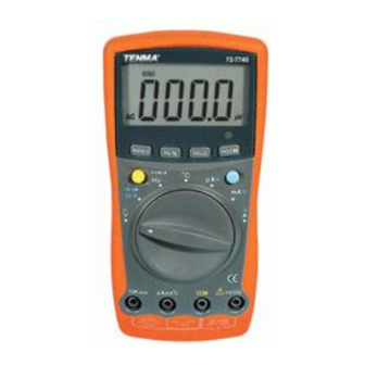
72-7740
Operating manual
Tenma 72-7740 Operating Manual
Hide thumbs
1
2
3
4
5
6
7
8
9
10
11
12
13
14
15
16
17
18
19
20
21
22
23
24
25
26
27
28
29
30
31
32
33
34
35
page
of
35
Go
/
35
Contents
Table of Contents
Bookmarks
Table of Contents
Table of Contents
Overview
Unpacking Inspection
Safety Information
Rules for Safe Operation
International Electrical Symbols
The Meter Structure
Rotary Switch
Functional Buttons
Display Symbols
Measurement Ranges
Manual Ranging and Autoranging
Measurement Operation A. DC Voltage Measurement
AC Voltage Measurement
Measuring Resistance
Testing for Continuity
Testing Diodes
Capacitance Measurement
Frequency Measurement
Measuring Duty Cycle
Temperature Measurement
DC or AC Current Measurement
The Use of Relative Value Mode
Operation of Hold Mode
The BLUE Button
Turning on the Display Backlight
The POWER Button
Sleep Mode (Model 72-7740 Only)
General Specifications
Accuracy Specifications
AC Voltage
Resistance
Continuity Test
Diode Test
Capacitance
Frequency & Duty Cycle
Temperature
DC Current
AC Current
Maintenance
Testing the Fuses
Replacing the Battery
Replacing the Fuses
RS232C Port Cable
Setting of RS232C Serial Ports
Advertisement
Quick Links
1
Capacitance Measurement
2
Accuracy Specifications
3
Replacing the Battery
Download this manual
Table of Contents
Title
Overview
Unpacking Inspection
Safety Information
Rules For Safe Operation
International Electrical Symbols
The Meter Structure
Rotary Switch
Functional Buttons
Display Symbols
Measurement Ranges
A.
Selecting a Measurement Range
B.
Manual Ranging and Autoranging
Measurement Operation
A.
DC Voltage Measurement
B.
AC Voltage Measurement
C.
Measuring Resistance
D.
Testing for Continuity
E.
Testing Diodes
F.
Capacitance Measurement
G.
Frequency Measurement
H.
Measuring Duty Cycle
I.
Temperature Measurement
J.
DC or AC Current Measurement
Operation of Hold Mode
The Use of Relative Value Mode
The POWER Button
The BLUE Button
Turning on the Display Backlight
Sleep Mode (Model 72-7740 only)
General Specifications
Accuracy Specifications
A.
DC Voltage
B.
AC Voltage
C.
Resistance
D.
Continuity Test
Model 72-7740/72-7745: OPERATING MANUAL
1
Page
3
4
4
5
6
7
8
9
11
12
12
14
15
16
17
18
19
20
21
22
22
24
24
25
25
25
25
26
27
27
27
28
Previous
Page
Next
Page
1
2
3
4
5
Advertisement
Table of Contents
Need help?
Do you have a question about the 72-7740 and is the answer not in the manual?
Ask a question
Questions and answers
Related Manuals for Tenma 72-7740
Multimeter Tenma 72-7720 Operating Manual
(34 pages)
Multimeter Tenma 72-7745 Operating Manual
(35 pages)
Multimeter Tenma 72-7765 Operating Manual
(41 pages)
Multimeter Tenma 72-7930 Operating Manual
(36 pages)
Multimeter Tenma 72-7780 User Manual
True rms digital multimeter (13 pages)
Multimeter Tenma 72-7780 Manual
True rms digital multimeter (13 pages)
Multimeter Tenma 72-7765A User Manual
Palm size digital multimeter (12 pages)
Multimeter Tenma 72-7770A User Manual
Palm size digital multimeter (12 pages)
Multimeter Tenma 72-7730A Operating Manual
Intelligent (69 pages)
Multimeter Tenma 72-7228 Operating Manual
Digital clamp multimeter (52 pages)
Multimeter Tenma 72-7224 Operating Manual
Digital clamp multimeters (47 pages)
Multimeter Tenma 72-8720 Manual
Digital bench multimeter (21 pages)
Multimeter Tenma 72-10395 Manual
Pocket size digital multimeter (9 pages)
Multimeter Tenma 72-2600 Manual
(9 pages)
Multimeter Tenma 72-1015 User Manual
Bench digital multimeter (26 pages)
Multimeter Tenma 72-9380A Manual
Pocket size digital multimeter (21 pages)
This manual is also suitable for:
72-7745
Table of Contents
Print
Rename the bookmark
Delete bookmark?
Delete from my manuals?
Login
Sign In
OR
Sign in with Facebook
Sign in with Google
Upload manual
Upload from disk
Upload from URL


Need help?
Do you have a question about the 72-7740 and is the answer not in the manual?
Questions and answers