Table of Contents
Advertisement
Quick Links
INSTALLATION AND OPERATION MANUAL
ValueLine
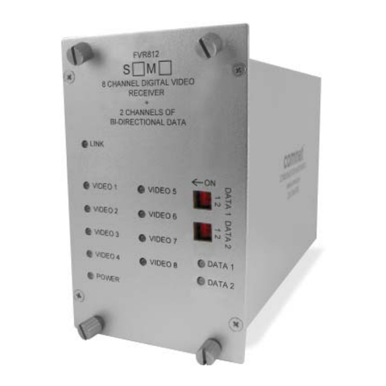
FVT/FVR812
8-CHANNEL DIGITALLY ENCODED VIDEO
+ 2 BI-DIRECTIONAL DATA CHANNELS
+ 1 BI-DIRECTIONAL CONTACT CLOSURE
The FVT/FVR812(M)(S)1 Series transmits eight (8) channels of video
utilizing state of the art digital encoding and decoding for high-quality video
transmission, along with two (2) channels of bi-directional data and one (1)
bi-directional contact closure over one single mode or multimode optical fiber.
This equipment is environmentally hardened and suitable for use in
unconditioned roadside or out-of plant installations.
The FVT/FVR812 is compatible with NTSC, PAL and SECAM video transmission
protocols and supports bi-directional RS232, 422 and 485 (2 & 4 Wire) data.
See Figure 4 on Page 3 for data selection.
See Figure 6 on Page 5 for contact switch positions.
Bi-Color LED indicators are provided to indicate the status of the system, video
and data. See Figure 7 on Page 5 for LED indication explanations.
These units may be directly plugged into the ComNet Rack (Part C1) or they
can operate as standalone modules. See Figure A on Page 6 for mounting
instructions.
See Figures 1 – 7 for complete installation details. No additional parts or
power supplies are required.
INS_FVT/FVR812_REV–
05/27/10
PAGE 1
Advertisement
Table of Contents

Related Manuals for Comnet ValueLine FVT812


Summary of Contents for Comnet ValueLine FVT812
- Page 1 Bi-Color LED indicators are provided to indicate the status of the system, video and data. See Figure 7 on Page 5 for LED indication explanations. These units may be directly plugged into the ComNet Rack (Part C1) or they can operate as standalone modules. See Figure A on Page 6 for mounting instructions.
- Page 2 INSTALLATION AND OPERATION MANUAL FVT/FVR812 FIGURE 1 – FVT/FVR812 TRANSMITTER AND RECEIVER MULTIMODE OR SINGLE MODE OPTICAL FIBER BLACK BLACK WITH WHITE STRIPE FIGURE 2 – FVT812 TRANSMITTER FIGURE 3 – FVR812 RECEIVER FRONT PANEL REAR PANEL FRONT PANEL REAR PANEL NOTE: Remove Electrical Connector for Rack Mount Units INS_FVT/FVR812_REV–...
- Page 3 INSTALLATION AND OPERATION MANUAL FVT/FVR812 FIGURE 4 – DATA SWITCH POSITIONS The mode for each data channel is configured using a pair switches on the front panel of the unit. 1) RS232 2) RS422, Bi-Phase or Manchester Switch 3) RS485 2-Wire, 4) RS485 4-Wire Sensornet 2) RS422,...
- Page 4 INSTALLATION AND OPERATION MANUAL FVT/FVR812 FIGURE 5 – DATA CONNECTIONS See Page 3 for Switch Settings Customer Customer Equipment FVT812 Equipment FVR812 Data Transmit DIN(-) Data Receive DOUT(-) RS-232 Data Receive DOUT(-) DIN(-) Data Transmit Signal Ground Signal Ground Data Out (+) DIN(+) Data In (+) DOUT(+)
- Page 5 INSTALLATION AND OPERATION MANUAL FVT/FVR812 FIGURE 6 – CONTACT SWITCH POSITIONS The four CONTACT switches on the front of the unit set the operating mode of the CONTACT OUT terminal pair. It can either function as an alarm to indicate fault conditions, or it can function as a contact closure to indicate the state of the CONTACT IN terminal pair on the rear of the unit at the other end of the fiber.
- Page 6 8 TURNBERRY PARK ROAD | GILDERSOME | MORLEY | LEEDS, UK LS27 7LE T: +44 (0)113 307 6400 | F: +44 (0)113 253 7462 | INFO-EUROPE@COMNET.NET INS_FVT/FVR812_REV– 05/27/10 © 2010 Communications Networks Corporation. All Rights Reserved. “ComNet” and the “ComNet Logo” are registered trademarks of Communication Networks, LLC. PAGE 6...
Need help?
Do you have a question about the ValueLine FVT812 and is the answer not in the manual?
Questions and answers