Advertisement
Table of Contents
INSTALLATION AND OPERATION MANUAL
FVT/FVR10D2I1C4E
10-BIT DIGITALLY ENCODED VIDEO
+ 2 BI-DIRECTIONAL DATA + AIPHONE
INTERCOM
™
+ 4 CONTACT CLOSURE
+ 100MB ETHERNET
+ REDUNDANT POINT-TO-POINT DUAL SFP OPTICAL PORTS
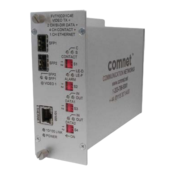
The FVT/FVR10D2I1C4E series utilize 10-bit digital video encoding and decoding
for high-quality video transmission that meets the requirements of EIA RS-250C
for short-haul video transmission. These environmentally hardened units provide
transmission of one video channel and two bi-directional data channels. They also
provide transmission of one Aiphone
intercom channel and four contact closure
™
channels with tamper supervision in addition to one 10/100Mb Ethernet channel.
The ComNet
FVT/FVR10D2I1C4E has dual optical (SFP) ports to provide a redundant
™
point-to-point fail safe topology in the event of loss of one fiber or one optical module.
Operational status can be monitored by using the web management interface
through the addition of the ComNet network managed chassis and network
management interface module.
Bi-color (red/green) LED indicators are provided for confirming operating status in
addition to alarm contacts for fault monitoring. See Figure 15 on Page 9 for LED
explanations.
Packaged in the exclusive ComNet ComFit housing, these units may be either wall
or rack-mounted (using ComNet C2 network-managed rack), or may be DIN-rail
mounted by the addition of ComNet model DINBKT1 adaptor plate. See Figure A on
Page 10 for mounting instructions.
INS_FVT/FVR20D2I1C4E_REV- 06/22/12 PAGE 1
Advertisement
Table of Contents

Summary of Contents for Comnet FVT10D2I1C4E
- Page 1 Packaged in the exclusive ComNet ComFit housing, these units may be either wall or rack-mounted (using ComNet C2 network-managed rack), or may be DIN-rail mounted by the addition of ComNet model DINBKT1 adaptor plate. See Figure A on Page 10 for mounting instructions.
-
Page 2: Front Panel
* One SFP required for point-to-point operation. Two SFPs required for redundant operation. NOTE: Remove PWR1 Electrical Consult factory for compatible SFP Modules. Connector for Rack Mount Units FIGURE 2 – FVT10D2I1C4E TRANSMITTER FIGURE 3 – FVR10D2I1C4E RECEIVER FRONT PANEL REAR PANEL... - Page 3 INSTALLATION AND OPERATION MANUAL FVT/FVR20D2I1C4E FIGURE 4 – RJ45 BREAK-OUT – FVT10D2I1C4E TRANSMITTER 4 pc. Factory Supplied RJ-45 PORTS D (DATA PORTS) Located on Rear Panel PIN # Wire Color Data Connections Blue DATA OUT – Orange DATA OUT +...
-
Page 4: Contact Input
INSTALLATION AND OPERATION MANUAL FVT/FVR20D2I1C4E FIGURE 5 – RJ45 BREAK-OUT – FVR10D2I1C4E RECEIVER 4 pc. Factory Supplied RJ-45 PORTS D (DATA PORTS) Located on Rear Panel PIN # Wire Color Data Connections Blue DATA OUT – Orange DATA OUT + Black DATA IN + RELAY OUT... - Page 5 INSTALLATION AND OPERATION MANUAL FVT/FVR20D2I1C4E FIGURE 6 – DATA SWITCH POSITIONS The mode for each data channel is configured using a set of two switches labeled DATA1 (S3) and DATA2 (S4), located on the front panel of the unit. DATA1 (S3) DATA2 (S4) Resulting Mode RS232...
- Page 6 INSTALLATION AND OPERATION MANUAL FVT/FVR20D2I1C4E FIGURE 8 – DATA CONNECTIONS See Page 5 for Switch Settings Customer Customer Equipment FVT10D2I1C4E Equipment FVR10D2I1C4E Data Transmit DIN(-) Data Receive DOUT(+) RS232 Data Receive DOUT(+) Data Transmit DIN(-) Signal Ground Signal Ground Data Out (+)
-
Page 7: Intercom Connections
Number of fibers and type of fiber connectors will be determined by selected SFP modules and if point-to-point or redundant modes are required. FIGURE 11 – AIPHONE INTERCOM CONNECTIONS ™ The units are designed to operate with the Aiphone LE-D and LEF intercom system. ™ FVT10D2I1C4E FVR10D2I1C4E PIN # Wire Color Aiphone Connections PIN # Wire Color Aiphone Connections Blue LE-D ‘-’... - Page 8 NOTE: These switch settings refer to the trans- inputs can be detected but open circuits cannot be detected. mitter (FVT10D2I1C4E). On the receiver Parallel Supervision – When a 1K resistor is connected in parallel (FVR10D2I1C4E), S1 SWITCH 1 inverts the across the contact closure input.
- Page 9 INSTALLATION AND OPERATION MANUAL FVT/FVR20D2I1C4E FIGURE 14 – ALARM SWITCH POSITIONS The mode for alarm operation is configured using a set of two switches labeled ALARM (S2) located on the front panel of the unit. There are two alarm out- puts on each unit.
- Page 10 8 TURNBERRY PARK ROAD | GILDERSOME | MORLEY | LEEDS, UK LS27 7LE T: +44 (0)113 307 6400 | F: +44 (0)113 253 7462 | INFO-EUROPE@COMNET.NET © 2013 Communications Networks Corporation. All Rights Reserved. “ComNet” and the “ComNet Logo” are registered trademarks of Communication Networks, LLC. INS_FVT/FVR20D2I1C4E_REV- 06/22/12 PAGE 10...


Need help?
Do you have a question about the FVT10D2I1C4E and is the answer not in the manual?
Questions and answers