Table of Contents
Advertisement
Quick Links
Advertisement
Table of Contents

Subscribe to Our Youtube Channel
Related Manuals for Texas Instruments LM8365EVM


Summary of Contents for Texas Instruments LM8365EVM
- Page 1 LM8365EVM User Guide User's Guide Literature Number: SNVU493 October 2015...
- Page 2 SNVU493 – October 2015 Introduction The Texas Instruments LM8365EVM evaluation module (EVM) helps designers evaluate the operation and performance of the LM8365 Micropower Undervoltage Supervisor with Programmable Output Delay. For this EVM, the 2.7 V reset threshold LM8365 will be used. The EVM demonstrates proper functionality of the LM8365 via selection of 3 distinct capacitors corresponding to programmable delay times.
-
Page 3: Input/Output Connector Description
Multiple capacitors can also be connected in parallel by placing multiple jumpers. Once all the connections to the LM8365EVM have been verified, power can be applied to VIN, and evaluation can begin. SNVU493 – October 2015... - Page 4 RESET pin outputting high. The LM8365 provides proper voltage supervision in critical situations like undervoltage input to a microprocessor. Figure 1. RST Response to Low VIN Applications SNVU493 – October 2015 Submit Documentation Feedback Copyright © 2015, Texas Instruments Incorporated...
- Page 5 Figure 2. RST Response to Threshold VIN SNVU493 – October 2015 Applications Submit Documentation Feedback Copyright © 2015, Texas Instruments Incorporated...
- Page 6 VCC has stabilized above the minimum operating voltage. Figure 3. 0.1 µF Capacitor Programmed Delay Applications SNVU493 – October 2015 Submit Documentation Feedback Copyright © 2015, Texas Instruments Incorporated...
- Page 7 Section 3 Programmed Delay with 0.1 µF Capacitor, we populate J3 instead. This corresponds to a CD capacitor of 1 µF. Figure 4. 1 µF Capacitor Programmed Delay SNVU493 – October 2015 Applications Submit Documentation Feedback Copyright © 2015, Texas Instruments Incorporated...
- Page 8 CD Voltage Behavior Aside from observing the programmed output delay, the LM8365EVM provides the option to observe the behavior of the selected capacitor(s). For this example, we use the same setup as Section 4 Programmed Delay with 1 µF Capacitor. The behavior of the 1 µF CD capacitor is shown in...
- Page 9 Figure 6 shows the reaction time of the RESET output when VIN falls below the RESET threshold. Figure 6. RST Output Low Response SNVU493 – October 2015 Applications Submit Documentation Feedback Copyright © 2015, Texas Instruments Incorporated...
-
Page 10: Board Layout
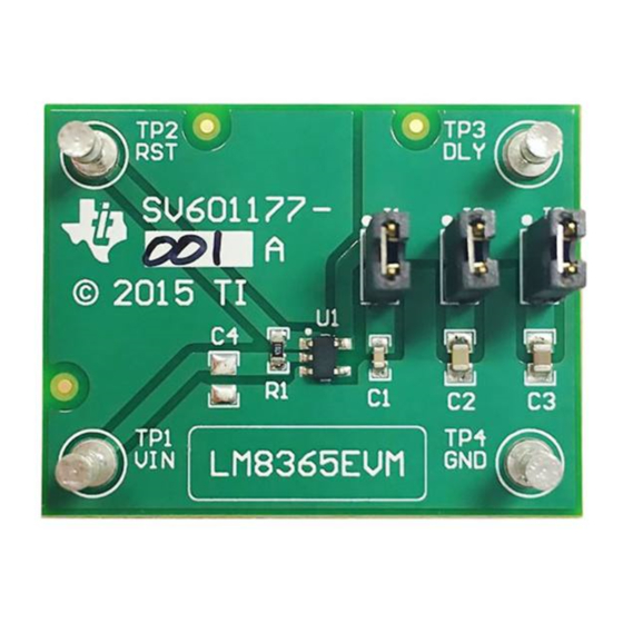
SNVU493 – October 2015 Board Layout Figure 7 shows the board layout for the LM8365EVM. Please note that we have provided an unpopulated footprint for C4 which allows room for an input capacitor. Figure 7. Top Layer Layout Board Layout SNVU493 –... - Page 11 SNVU493 – October 2015 Schematic Figure 8. LM8365EVM Schematic SNVU493 – October 2015 Schematic Submit Documentation Feedback Copyright © 2015, Texas Instruments Incorporated...
-
Page 12: Bill Of Materials
SNVU493 – October 2015 Bill of Materials Table 2. LM8365EVM Bill of Materials COUNT REF DES DESCRIPTION PACKAGE REF PART NUMBER Printed Circuit Board SV601177 CAP, CERM, 0.01µF, 16V, +/- 10%, MuRata GRM188R71C103KA01 X7R, 0603 CAP, CERM, 0.1µF, 16V, +/- 10%,... -
Page 13: Related Documentation
SNVU493 – October 2015 Related Documentation LM8365 Micropower Undervoltage Sensing Circuits with Programmable Output Delay datasheet (SNVS233). Revision History DATE REVISION NOTES October 2015 Initial release. SNVU493 – October 2015 Related Documentation Submit Documentation Feedback Copyright © 2015, Texas Instruments Incorporated... - Page 14 STANDARD TERMS AND CONDITIONS FOR EVALUATION MODULES Delivery: TI delivers TI evaluation boards, kits, or modules, including any accompanying demonstration software, components, or documentation (collectively, an “EVM” or “EVMs”) to the User (“User”) in accordance with the terms and conditions set forth herein. Acceptance of the EVM is expressly subject to the following terms and conditions.
- Page 15 FCC Interference Statement for Class B EVM devices NOTE: This equipment has been tested and found to comply with the limits for a Class B digital device, pursuant to part 15 of the FCC Rules. These limits are designed to provide reasonable protection against harmful interference in a residential installation.
- Page 16 【無線電波を送信する製品の開発キットをお使いになる際の注意事項】 開発キットの中には技術基準適合証明を受けて いないものがあります。 技術適合証明を受けていないもののご使用に際しては、電波法遵守のため、以下のいずれかの 措置を取っていただく必要がありますのでご注意ください。 1. 電波法施行規則第6条第1項第1号に基づく平成18年3月28日総務省告示第173号で定められた電波暗室等の試験設備でご使用 いただく。 2. 実験局の免許を取得後ご使用いただく。 3. 技術基準適合証明を取得後ご使用いただく。 なお、本製品は、上記の「ご使用にあたっての注意」を譲渡先、移転先に通知しない限り、譲渡、移転できないものとします。 上記を遵守頂けない場合は、電波法の罰則が適用される可能性があることをご留意ください。 日本テキサス・イ ンスツルメンツ株式会社 東京都新宿区西新宿6丁目24番1号 西新宿三井ビル 3.3.3 Notice for EVMs for Power Line Communication: Please see http://www.tij.co.jp/lsds/ti_ja/general/eStore/notice_02.page 電力線搬送波通信についての開発キットをお使いになる際の注意事項については、次のところをご覧くださ い。http://www.tij.co.jp/lsds/ti_ja/general/eStore/notice_02.page SPACER EVM Use Restrictions and Warnings: 4.1 EVMS ARE NOT FOR USE IN FUNCTIONAL SAFETY AND/OR SAFETY CRITICAL EVALUATIONS, INCLUDING BUT NOT LIMITED TO EVALUATIONS OF LIFE SUPPORT APPLICATIONS.
- Page 17 Notwithstanding the foregoing, any judgment may be enforced in any United States or foreign court, and TI may seek injunctive relief in any United States or foreign court. Mailing Address: Texas Instruments, Post Office Box 655303, Dallas, Texas 75265 Copyright © 2015, Texas Instruments Incorporated...
-
Page 18: Important Notice
IMPORTANT NOTICE Texas Instruments Incorporated and its subsidiaries (TI) reserve the right to make corrections, enhancements, improvements and other changes to its semiconductor products and services per JESD46, latest issue, and to discontinue any product or service per JESD48, latest issue.
Need help?
Do you have a question about the LM8365EVM and is the answer not in the manual?
Questions and answers