Advertisement
www.ti.com
EVM User's Guide: LM65645EVM
LM65645EVM Evaluation Module
Description
The Texas Instruments LM65645EVM evaluation
module (EVM) helps designers evaluate the operation
and performance of the LM65645 family of wide
input voltage buck converters. The LM65645 family
are easy to use, synchronous, step-down converters
capable of supplying up to 2.5A, 3.5A, or 4.5A of load
current from an input voltage as high as 65V.
SNVU914 – JULY 2024
Submit Document Feedback
Features
•
3V to 65V wide input voltage range
•
5V, 3.3V, and adjustable output voltage options
•
Up to 4.5A output current
•
300kHz to 2.2MHz switching frequency
•
Minimized switch node ringing to reduce
Electromagnetic Interference (EMI)
•
Input transient capability up to 70V
LM65645EVM
Copyright © 2024 Texas Instruments Incorporated
Description
LM65645EVM Evaluation Module
1
Advertisement
Table of Contents

Related Manuals for Texas Instruments LM65645EVM


Summary of Contents for Texas Instruments LM65645EVM
- Page 1 Description EVM User's Guide: LM65645EVM LM65645EVM Evaluation Module Description Features The Texas Instruments LM65645EVM evaluation • 3V to 65V wide input voltage range module (EVM) helps designers evaluate the operation • 5V, 3.3V, and adjustable output voltage options and performance of the LM65645 family of wide •...
-
Page 2: Kit Contents
1 Evaluation Module Overview 1.1 Introduction The LM65645EVM is configured to deliver a 5V output to a load requiring 4.5A or less. The LM65645EVM can be used in many different configurations by substituting other versions of the LM656x5 and re-configuring the board components. -
Page 3: Power Requirements
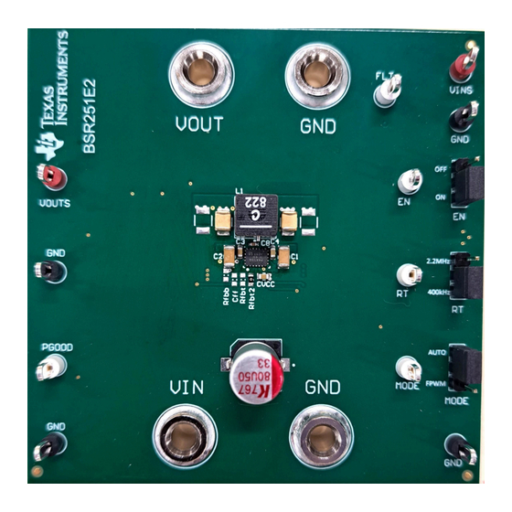
2 Hardware 2.1 Additional Images Figure 2-1 Figure 2-2 show the front and back of the LM65645EVM respectively. Figure 2-1. LM65645EVM Top Side Figure 2-2. LM65645EVM Bottom Side 2.2 Power Requirements Any power source in the range of 6V to 63V, and capable of delivering 3A, can be used to evaluate the LM65645EVM, under normal conditions. -
Page 4: Setup And Operation
2.3 Setup and Operation This section describes the connectors, test points, and jumpers on the EVM and how to properly connect, set up, and use the LM65645EVM See Figure 2-3 for location of connectors and jumpers and typical setup. - Page 5 Table 4-1. Load EN jumper = ON VOUT RT jumper = 400kHz MODE jumper = AUTO Input Supply Figure 2-3. LM65645EVM Setup SNVU914 – JULY 2024 LM65645EVM Evaluation Module Submit Document Feedback Copyright © 2024 Texas Instruments Incorporated...
- Page 6 Hardware www.ti.com Source T = B/A Frequency Response Analyzer Figure 2-4. LM65645EVM Loop Response Connections LM65645EVM Evaluation Module SNVU914 – JULY 2024 Submit Document Feedback Copyright © 2024 Texas Instruments Incorporated...
- Page 7 = 5V = 0A to = 24V FPWM Mode = 5V 4.5A (1μs) 4.5A (1μs) Figure 3-6. Load Transient (AUTO) Figure 3-5. Load Transient (FPWM) SNVU914 – JULY 2024 LM65645EVM Evaluation Module Submit Document Feedback Copyright © 2024 Texas Instruments Incorporated...
- Page 8 2V/div 20ms/div = 1A = 24V = 5V Figure 3-9. Short Circuit = 4.5A 400kHz = 24V = 5V LM65645EVM Figure 3-10. Thermal Image LM65645EVM Evaluation Module SNVU914 – JULY 2024 Submit Document Feedback Copyright © 2024 Texas Instruments Incorporated...
- Page 9 Hardware Design Files 4 Hardware Design Files 4.1 Schematics Figure 4-1. LM65645EVM Schematic SNVU914 – JULY 2024 LM65645EVM Evaluation Module Submit Document Feedback Copyright © 2024 Texas Instruments Incorporated...
-
Page 10: Pcb Layouts
Hardware Design Files www.ti.com 4.2 PCB Layouts Figure 4-2. PCB Top Layer Figure 4-3. PCB Ground Layer (Directly Below Top Layer) LM65645EVM Evaluation Module SNVU914 – JULY 2024 Submit Document Feedback Copyright © 2024 Texas Instruments Incorporated... - Page 11 Hardware Design Files Figure 4-4. PCB Signal Layer Figure 4-5. PCB Bottom Layer SNVU914 – JULY 2024 LM65645EVM Evaluation Module Submit Document Feedback Copyright © 2024 Texas Instruments Incorporated...
-
Page 12: Bill Of Materials (Bom)
Hardware Design Files www.ti.com 4.3 Bill of Materials (BOM) Table 4-1. LM65645EVM BOM (With Options) Designator Alias Quantity Value Description Part Number Chip Multilayer Ceramic Capacitor for General C3, C4 2.2µF GRM21BD72A225ME01K Purpose 2.2uF ±20% 100V X7T SMD 0805 CAP, AL, 100uF, 63V, +/– 20%, 0.35 ohm,... -
Page 13: Additional Information
Additional Information 5 Additional Information 5.1 Trademarks All trademarks are the property of their respective owners. SNVU914 – JULY 2024 LM65645EVM Evaluation Module Submit Document Feedback Copyright © 2024 Texas Instruments Incorporated... - Page 14 STANDARD TERMS FOR EVALUATION MODULES Delivery: TI delivers TI evaluation boards, kits, or modules, including any accompanying demonstration software, components, and/or documentation which may be provided together or separately (collectively, an “EVM” or “EVMs”) to the User (“User”) in accordance with the terms set forth herein.
- Page 15 www.ti.com Regulatory Notices: 3.1 United States 3.1.1 Notice applicable to EVMs not FCC-Approved: FCC NOTICE: This kit is designed to allow product developers to evaluate electronic components, circuitry, or software associated with the kit to determine whether to incorporate such items in a finished product and software developers to write software applications for use with the end product.
- Page 16 www.ti.com Concernant les EVMs avec antennes détachables Conformément à la réglementation d'Industrie Canada, le présent émetteur radio peut fonctionner avec une antenne d'un type et d'un gain maximal (ou inférieur) approuvé pour l'émetteur par Industrie Canada. Dans le but de réduire les risques de brouillage radioélectrique à...
- Page 17 www.ti.com EVM Use Restrictions and Warnings: 4.1 EVMS ARE NOT FOR USE IN FUNCTIONAL SAFETY AND/OR SAFETY CRITICAL EVALUATIONS, INCLUDING BUT NOT LIMITED TO EVALUATIONS OF LIFE SUPPORT APPLICATIONS. 4.2 User must read and apply the user guide and other available documentation provided by TI regarding the EVM prior to handling or using the EVM, including without limitation any warning or restriction notices.
- Page 18 Notwithstanding the foregoing, any judgment may be enforced in any United States or foreign court, and TI may seek injunctive relief in any United States or foreign court. Mailing Address: Texas Instruments, Post Office Box 655303, Dallas, Texas 75265 Copyright © 2023, Texas Instruments Incorporated...
- Page 19 TI products. TI’s provision of these resources does not expand or otherwise alter TI’s applicable warranties or warranty disclaimers for TI products. TI objects to and rejects any additional or different terms you may have proposed. IMPORTANT NOTICE Mailing Address: Texas Instruments, Post Office Box 655303, Dallas, Texas 75265 Copyright © 2024, Texas Instruments Incorporated...
Need help?
Do you have a question about the LM65645EVM and is the answer not in the manual?
Questions and answers