Table of Contents
Advertisement
Quick Links
CONTENTS
1
INTRODUCTION ................................................................................................... 1
2
SETUP .................................................................................................................. 2
3
OPERATION ......................................................................................................... 5
4
INSTALLING THE SENSOR AFE SOFTWARE ................................................... 10
5
BOARD LAYOUT ................................................................................................ 11
6
SCHEMATIC ....................................................................................................... 12
7
BOM .................................................................................................................... 13
1
Connection Diagram ............................................................................................... 2
2
Jumper Setting (Default) for voltage reading ........................................................... 3
3
LMP91051EVM to SPIO-4 Board Connection ......................................................... 4
4
Sensor AFE Items of Interest .................................................................................. 5
5
Recommended LMP91051 Configuration for a voltage Reading ............................. 7
6
Sensor Database Window ..................................................................................... 8
7
Reults of DC Reading ............................................................................................. 9
8
LMP91051EVM's J3 for SPI Signals ..................................................................... 10
9
LMP91051EVM Layout ......................................................................................... 11
8
LMP91051EVM Schematic ................................................................................... 12
1
Jumpers for Voltage Measurement ......................................................................... 3
2
LMP91051EVM Bill of Materials............................................................................ 13
1.
Introduction
The LMP91051 Design Kit (consisting of the LMP91051 Evaluation Module, the SPIO-4 Digital Controller
Board, the Sensor AFE software, and this user's guide) is designed to ease evaluation and design-in of Texas
Instrument's LMP91051 Configurable AFE for Nondispersive Infrared (NDIR).
Data capturing and evaluations are simplified by connecting the SPIO-4 Digital Controller Board (SPIO-4 board)
to a PC via USB and running the Sensor AFE software. The data capture board will generate the SPI signals
to communicate to and capture data from the LMP91051. The user will also have the option to evaluate the
LMP91051 without using the SPIO-4 board or the Sensor AFE software.
The on board data converter will digitize the LMP91051's analog output, and the software will display these
results in time domain and histogram. The software also allows customers to write to and read from registers,
to configure the device's gain, output offset, and common mode voltage, and most importantly, to configure and
learn about the LMP91051.
October 2012
LMP91051EVM User's Guide
LIST OF FIGURES
LIST OF TABLES
User's Guide
October 2012
LMP91051EVM User's Guide
Advertisement
Table of Contents

Related Manuals for Texas Instruments LMP91051EVM


Summary of Contents for Texas Instruments LMP91051EVM
-
Page 1: Table Of Contents
LIST OF FIGURES Connection Diagram ....................2 Jumper Setting (Default) for voltage reading ............3 LMP91051EVM to SPIO-4 Board Connection ............4 Sensor AFE Items of Interest .................. 5 Recommended LMP91051 Configuration for a voltage Reading ......7 Sensor Database Window ..................8 Reults of DC Reading ..................... -
Page 2: Setup
LMP91051EVM. 2.1. Connection Diagram Figure 1 shows the connection between the LMP91051 Evaluation Module (LMP91051EVM), SPIO-4 board, and a personal computer with the Sensor AFE software. LMP91051 can be powered using external power supplies or from the SPIO-4 board. -
Page 3: Jumper Setting (Default) For Voltage Reading
IN to CMOUT for easy evaluation. J2: IN2 to CMOUT Open Connect LMP91051 IN2 to CMOUT. Note: Board is provided with this jumper open. Use provided jumper to short IN to CMOUT for easy evaluation. LMP91051EVM User’s Guide October 2012... -
Page 4: Lmp91051Evm To Spio-4 Board Connection
2. Connect SPIO-4 board to a PC via USB. 3. Use a multimeter to measure LMP91051EVM’s +5V test point; it should be approximately 5V. If it is not, check your power supplies and jumpers. Measure test point VREF_ADC; it should be approximately 4.1V. -
Page 5: Operation
Registers will not be updated until this step is done. g. Zoom In/Out Diagram Image: Zoom in and out of the virtual device image. h. Show Tutorial: Takes you to the interactive Software Overview videos. LMP91051EVM User’s Guide October 2012... - Page 6 Follow the step-by-step instructions under the “HelpBar” mini-tab (left hand side of the GUI) to configure the LMP91051 for this example. These step-by-step instructions are discussed in details below, and the recommended configuration should look similar to Figure 5. LMP91051EVM User’s Guide snou034...
-
Page 7: Recommended Lmp91051 Configuration For A Voltage Reading
1. Step 1: Select a Sensor – Sensor Database window opens. See Figure 6. Step 1: Click sensor type (Thermopile) and the sensors will show in the bottom table. Step 2: Click sensor and then click “Select” button on the left to use this sensor. LMP91051EVM User’s Guide October 2012... -
Page 8: Sensor Database Window
10. Step 10: Performance - click on the “Performance” mini-tab. This tab displays the Estimated Device Performance based on device configuration and user input device Supply and IC Temp .This tab also displays the Measured System Performance if you’ve connected a board and ran the LMP91051. LMP91051EVM User’s Guide snou034... -
Page 9: Reults Of Dc Reading
If using the SPIO-4 power to source VDD, then do the following: 1. Jumper pins 1 and 2 of JP1 to connect +3.3V SPIO-4 power to VDD_DUT. The schematic for the LMP91051EVM can be seen in Figure 10. LMP91051EVM User’s Guide... -
Page 10: Installing The Sensor Afe Software
Download the zip file onto your local hard drive. Unzip this folder. 2. Installing the Driver - skip this step if you don’t have the LMP91051EVM and SPIO4 digital controller board. a. See the provided Installation Guide For SensorAFE Drivers.pdf. -
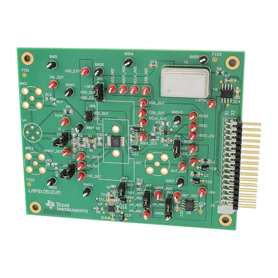
Page 11: Board Layout
See the provided Installation Guide for LMP91050 SensorAFE Software.pdf i. Note: If you run the software without the boards, you’ll get an error message. Ignore that error message and click “Ok” to continue. Board Layout Figure 9: LMP91051EVM Layout LMP91051EVM User’s Guide October 2012... -
Page 12: Schematic
Schematic Figure 10: LMP91051EVM Schematic... -
Page 13: Bom
LMP91051EVM Bill of Materials Item Designator Description Manufacturer PartNumber Quantity +3P3V, +5V, A0_DUT, A1_DUT, CMOUT_DUT, CSB_ADC, Test Point, TH, Compact, Red Keystone Electronics 5005 CSB_DUT, DOUT_ADC, IN1_DUT, IN2_DUT, MISO, MOSI, MOSI_EN, OUT_DUT, REF_ADC, SCLK_ADC, SCLK_DUT, SDIO_DUT, TEMP, VA_ADC, VDD_DUT, VDD_EXT, VIO,... - Page 14 0603 RES, 51.1 ohm, 1%, 0.1W, Vishay-Dale CRCW060351R1FKEA 0603 R11, R12, R13, R14 Vishay-Dale CRCW06031R00JNEA LMP91051 Texas Instruments LMP91051 16-Bit, 50 to 250 kSPS, Texas Instruments ADC141S628QIMMX/NOP Differential Input, MicroPower ADC, 10-pin Mini SOIC, Pb- Free Non-Inverting 3-State Buffer Texas Instruments...
- Page 15 EVALUATION BOARD/KIT/MODULE (EVM) ADDITIONAL TERMS Texas Instruments (TI) provides the enclosed Evaluation Board/Kit/Module (EVM) under the following conditions: The user assumes all responsibility and liability for proper and safe handling of the goods. Further, the user indemnifies TI from all claims arising from the handling or use of the goods.
- Page 16 This equipment has been tested and found to comply with the limits for a Class A digital device, pursuant to part 15 of the FCC Rules. These limits are designed to provide reasonable protection against harmful interference when the equipment is operated in a commercial environment. This equipment generates, uses, and can radiate radio frequency energy and, if not installed and used in accordance with the instruction manual, may cause harmful interference to radio communications.
- Page 17 Please note that if you could not follow the instructions above, you will be subject to penalties of Radio Law of Japan. Texas Instruments Japan Limited (address) 24-1, Nishi-Shinjuku 6 chome, Shinjuku-ku, Tokyo, Japan http://www.tij.co.jp...
- Page 18 FDA Class III or similar classification, then you must specifically notify TI of such intent and enter into a separate Assurance and Indemnity Agreement. Mailing Address: Texas Instruments, Post Office Box 655303, Dallas, Texas 75265 Copyright © 2012, Texas Instruments Incorporated...
- Page 19 IMPORTANT NOTICE Texas Instruments Incorporated and its subsidiaries (TI) reserve the right to make corrections, enhancements, improvements and other changes to its semiconductor products and services per JESD46, latest issue, and to discontinue any product or service per JESD48, latest issue.
- Page 20 Authorized Distribution Brand: Website: Welcome to visit www.ameya360.com Contact Us: Address: 401 Building No.5, JiuGe Business Center, Lane 2301, Yishan Rd Minhang District, Shanghai , China Sales: Direct +86 (21) 6401-6692 Email amall@ameya360.com 800077892 Skype ameyasales1 ameyasales2 Customer Service: Email service@ameya360.com Partnership:...
Need help?
Do you have a question about the LMP91051EVM and is the answer not in the manual?
Questions and answers