Table of Contents
Advertisement
Quick Links
1
Introduction
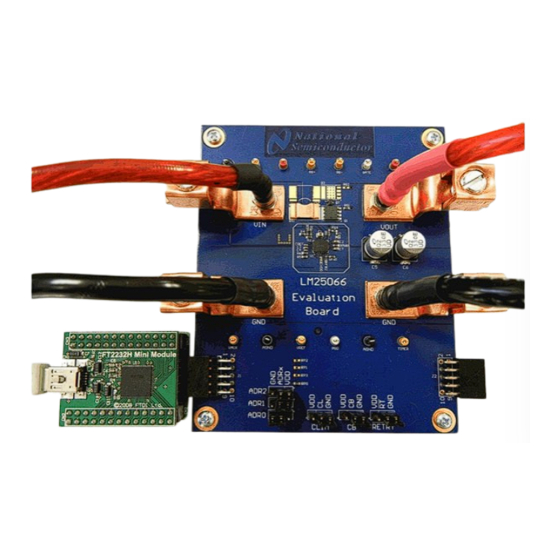
The LM25066EVK evaluation kit provides the design engineer with a fully functional, intelligent monitoring
and hot-swap protection board designed for positive voltage systems. This application note describes the
various functions of the evaluation board, how to test and evaluate it, and how to use the companion GUI.
The GUI is used to collect telemetry, configure warning and fault thresholds, and assist the designer with
selection of the external components for a specific application. Use of the advanced telemetry and
monitoring capabilities of the LM25066 requires external control via the Power Management Bus (PMBus)
interface. However, the LM25066 is capable of acting as a hot-swap and protection circuit without any
PMBus intervention. Please check the LM25066 System Power Management & Protection IC with PMBus
(SNVS654) data sheet for the latest software and data sheet information.
2
PCB Features
•
Input voltage range: 2.9V to 16V (limited by input clamp D1)
•
Programmable current limit: set to 50A (±8%)
•
Q1 power limit: 80W (typical)
•
UVLO thresholds: 2.9V and 3.1V
•
PGD thresholds: 10.8V and 10.25V
•
Insertion delay: 147 ms (typical)
•
Fault time-out period: 8.9 ms
•
Restart time: 1.1 seconds
•
PCB size: 3.5" x 4.2"
•
Solution size: 0.7" x 0.7"
Panduit is a registered trademark of Panduit Corp.
All other trademarks are the property of their respective owners.
SNVA464C – December 2010 – Revised April 2013
Submit Documentation Feedback
AN-2100 LM25066 Evaluation Board
Copyright © 2010–2013, Texas Instruments Incorporated
SNVA464C – December 2010 – Revised April 2013
AN-2100 LM25066 Evaluation Board
User's Guide
1
Advertisement
Table of Contents

Related Manuals for Texas Instruments LM25066EVK


Summary of Contents for Texas Instruments LM25066EVK
- Page 1 AN-2100 LM25066 Evaluation Board Introduction The LM25066EVK evaluation kit provides the design engineer with a fully functional, intelligent monitoring and hot-swap protection board designed for positive voltage systems. This application note describes the various functions of the evaluation board, how to test and evaluate it, and how to use the companion GUI.
-
Page 2: Simplified Schematic
Footprints for components RS2 and Q2 are not populated and are provided to accommodate evaluation of hot-swap designs with current levels greater than 50A. The LM25066EVK is supplied with the PMBus slave address set to 0x16 as dictated by the configuration of the ADR0, ADR1, and ADR2 jumper connections. -
Page 3: Hardware Setup Steps
The LM25066 should be detected on the PMBus and an initial screen should appear as shown in Figure SNVA464C – December 2010 – Revised April 2013 AN-2100 LM25066 Evaluation Board Submit Documentation Feedback Copyright © 2010–2013, Texas Instruments Incorporated... - Page 4 Power button located at the top right of the LM25066 block representation. AN-2100 LM25066 Evaluation Board SNVA464C – December 2010 – Revised April 2013 Submit Documentation Feedback Copyright © 2010–2013, Texas Instruments Incorporated...
- Page 5 The plotting tool allows the user to select the desired data to be plotted. Up to two different parameters may be plotted simultaneously, as shown in Figure SNVA464C – December 2010 – Revised April 2013 AN-2100 LM25066 Evaluation Board Submit Documentation Feedback Copyright © 2010–2013, Texas Instruments Incorporated...
- Page 6 Device Configuration panel. This panel, shown in Figure 7, is enabled by clicking the Gear button shown in the LM25066 block representation. AN-2100 LM25066 Evaluation Board SNVA464C – December 2010 – Revised April 2013 Submit Documentation Feedback Copyright © 2010–2013, Texas Instruments Incorporated...
- Page 7 1.8 times (CB = GND) or 3.6 times (CB = VDD) the current limit threshold. Fault SNVA464C – December 2010 – Revised April 2013 AN-2100 LM25066 Evaluation Board Submit Documentation Feedback Copyright © 2010–2013, Texas Instruments Incorporated...
- Page 8 Design Tool section. To open the design tool, click the Wrench button located in the LM25066 block representation which will display the window as shown in Figure AN-2100 LM25066 Evaluation Board SNVA464C – December 2010 – Revised April 2013 Submit Documentation Feedback Copyright © 2010–2013, Texas Instruments Incorporated...
- Page 9 Make sure to change the RETRY jumper to match the design tool schematic when changing the default retry setting. SNVA464C – December 2010 – Revised April 2013 AN-2100 LM25066 Evaluation Board Submit Documentation Feedback Copyright © 2010–2013, Texas Instruments Incorporated...
- Page 10 SMBus Alert and PGOOD interrupts, and to turn the output on and off with the OPERATION button. AN-2100 LM25066 Evaluation Board SNVA464C – December 2010 – Revised April 2013 Submit Documentation Feedback Copyright © 2010–2013, Texas Instruments Incorporated...
- Page 11 CLEAR_FAULTS command was issued. SNVA464C – December 2010 – Revised April 2013 AN-2100 LM25066 Evaluation Board Submit Documentation Feedback Copyright © 2010–2013, Texas Instruments Incorporated...
-
Page 12: Theory Of Operation
PGD thresholds are set by resistors RFB1 and RFB2. Internal current sources at the UVLO, OVLO, and FB pins provide hysteresis for these thresholds. AN-2100 LM25066 Evaluation Board SNVA464C – December 2010 – Revised April 2013 Submit Documentation Feedback Copyright © 2010–2013, Texas Instruments Incorporated... - Page 13 R1. The UVLO thresholds are set with two resistors (R1, R2) as shown in Figure SNVA464C – December 2010 – Revised April 2013 AN-2100 LM25066 Evaluation Board Submit Documentation Feedback Copyright © 2010–2013, Texas Instruments Incorporated...
- Page 14 With the circuit in normal operation, the LM25066 can be shutdown by grounding the UVLO/EN pin or by clicking the Power button on the LM25066 block representation in the GUI. AN-2100 LM25066 Evaluation Board SNVA464C – December 2010 – Revised April 2013 Submit Documentation Feedback Copyright © 2010–2013, Texas Instruments Incorporated...
- Page 15 Note that it has been verified, assuming correct TVS placement, that operation of the LM25066 without C1 is feasible. SNVA464C – December 2010 – Revised April 2013 AN-2100 LM25066 Evaluation Board Submit Documentation Feedback Copyright © 2010–2013, Texas Instruments Incorporated...
-
Page 16: Performance Characteristics
5V/DIV VOUT VOUT 10V/DIV 40 ms/DIV 400 ms/DIV Figure 19. PGD Power up/Power down Behavior Figure 20. Restart Timing AN-2100 LM25066 Evaluation Board SNVA464C – December 2010 – Revised April 2013 Submit Documentation Feedback Copyright © 2010–2013, Texas Instruments Incorporated... - Page 17 5 15 25 35 45 55 65 75 85 TEMPERATURE (° C) TEMPERATURE (° C) Figure 21. IIN Error vs Temperature Figure 22. PIN Error vs Temperature SNVA464C – December 2010 – Revised April 2013 AN-2100 LM25066 Evaluation Board Submit Documentation Feedback Copyright © 2010–2013, Texas Instruments Incorporated...
- Page 18 Schematic www.ti.com Schematic Figure 23. LM25066 Evaluation Board Schematic AN-2100 LM25066 Evaluation Board SNVA464C – December 2010 – Revised April 2013 Submit Documentation Feedback Copyright © 2010–2013, Texas Instruments Incorporated...
-
Page 19: Bill Of Materials
System Power Managment and Texas Instruments LM25066 Protection IC VIN_TP, Test Point, TH, Miniature, Red Keystone Electronics 5000 VOUT_TP SNVA464C – December 2010 – Revised April 2013 AN-2100 LM25066 Evaluation Board Submit Documentation Feedback Copyright © 2010–2013, Texas Instruments Incorporated... -
Page 20: Pc Board Layout
PC Board Layout www.ti.com PC Board Layout Figure 24. Board Top Layer Figure 25. Board Mid Layer 1 AN-2100 LM25066 Evaluation Board SNVA464C – December 2010 – Revised April 2013 Submit Documentation Feedback Copyright © 2010–2013, Texas Instruments Incorporated... - Page 21 PC Board Layout www.ti.com Figure 26. Board Mid Layer 2 Figure 27. Board Bottom Layer (viewed From Top) SNVA464C – December 2010 – Revised April 2013 AN-2100 LM25066 Evaluation Board Submit Documentation Feedback Copyright © 2010–2013, Texas Instruments Incorporated...
-
Page 22: Important Notice
IMPORTANT NOTICE Texas Instruments Incorporated and its subsidiaries (TI) reserve the right to make corrections, enhancements, improvements and other changes to its semiconductor products and services per JESD46, latest issue, and to discontinue any product or service per JESD48, latest issue. -
Page 23: Texas Instruments
Mouser Electronics Authorized Distributor Click to View Pricing, Inventory, Delivery & Lifecycle Information: Texas Instruments LM25066EVK/NOPB...
Need help?
Do you have a question about the LM25066EVK and is the answer not in the manual?
Questions and answers