Table of Contents
Advertisement
Quick Links
Advertisement
Table of Contents

Related Manuals for ATEN CS724KM-AT


Summary of Contents for ATEN CS724KM-AT
- Page 1 4-Port USB KM Switch CS724KM User Manual www.aten.com...
-
Page 2: Emc Information
CS724KM User Manual EMC Information FEDERAL COMMUNICATIONS COMMISSION INTERFERENCE STATEMENT: This equipment has been tested and found to comply with the limits for a Class A digital device, pursuant to Part 15 of the FCC Rules. These limits are designed to provide reasonable protection against harmful interference when the equipment is operated in a commercial environment. -
Page 3: User Information
Japan 81-3-5615-5811 Korea 82-2-467-6789 North America 1-888-999-ATEN ext 4988 1-949-428-1111 User Notice All information, documentation, and specifications contained in this manual are subject to change without prior notification by the manufacturer. The manufacturer makes no representations or warranties, either expressed or implied, with respect to the contents hereof and specifically disclaims any warranties as to merchantability or fitness for any particular purpose. -
Page 4: Package Contents
Copyright © 2018 ATEN® International Co., Ltd. Manual Date: 2018-07-03 The ATEN logo are registered trademarks of ATEN International Co., Ltd. All rights reserved. All other brand names and trademarks are the registered property of their respective owners. -
Page 5: Table Of Contents
CS724KM User Manual Contents EMC Information ..........ii RoHS. - Page 6 CS724KM User Manual 4. Hotkey Operation Port Switching..........15 Cycling Through the Ports.
- Page 7 CS724KM User Manual Firmware Upgrade........51 KM Status .
-
Page 8: About This Manual
CS724KM User Manual About this Manual This user manual is provided to help you get the most from your CS724KM unit. It covers all aspects of installation, configuration and operation. An overview of the information found in the manual is provided below. Chapter 1, Introduction, introduces you to the CS724KM. -
Page 9: Conventions
For information about all ATEN products and how they can help you connect without limits, visit ATEN on the Web or contact an ATEN Authorized Reseller. Visit ATEN on the Web for a list of locations and telephone numbers: International http://www.aten.com... - Page 10 CS724KM User Manual This Page Intentionally Left Blank...
-
Page 11: Introduction
RS-232 commands. The mouse cursor method adopts ATEN’s exclusive Boundless Switching technology, which enables users to switch between multiple computers in multi-monitor extended desktops by simply moving the mouse cursor across any of the display borders in any direction to instantly select the target computer and take full control. -
Page 12: Features
CS724KM User Manual Features Single USB keyboard and mouse controls up to 4 computers Daisy-chain two CS724KM units to control up to 8 computers with a single keyboard and mouse Boundless Switching – simply move the mouse cursor across the display border and onto the corresponding display of the target computer to switch the keyboard/mouse operations from one computer to the next Boundless Switching Configuration Utility –... -
Page 13: Requirements
Chapter 1. Introduction Requirements Console A USB mouse A USB keyboard Speakers Computers The following equipment must be available on each computer: Video Display USB Type A port Audio ports Operating Systems Version Windows 2K / XP / 2003 / 2008 / Vista (x64 / x86) / 7 / 10 and higher... -
Page 14: Components
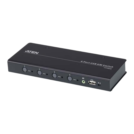
CS724KM User Manual Components CS724KM Front View Component Description Port For manual port selection, press a port selection pushbutton Selection to bring the KM focus to the computer attached to its Pushbuttons corresponding port. Audio Port The cables from your speakers plug in here. The speakers plugged in here have priority over those on the rear panel. - Page 15 Chapter 1. Introduction Component Description Port LEDs The four Port LEDs are built into the front panel. Lights green to indicate that the computer attached to its corresponding port is the one that has the keyboard/ mouse, USB hub and audio focus.
-
Page 16: Cs724Km Rear View
CS724KM User Manual CS724KM Rear View Component Description Power Jack The power adapter cable (not included in the package) plugs into this jack. USB peripherals (printers, scanners, drives etc.) plug into Peripheral this port. Port Serial Port This RJ-45 port is used to send serial commands (see RS- 232 Commands, page 41) and setup daisy chain installations (see Daisy Chain Installation, page 10). -
Page 17: Hardware Setup
Chapter 2 Hardware Setup 1. Important safety information regarding the placement of this device is provided on page 55. Please review it before proceeding. 2. Make sure that power to all the devices you will be installing has been turned off. You must unplug the power cords of any computers that have the Keyboard Power On function. - Page 18 CS724KM User Manual 9. Power on the computers.
-
Page 19: Installation Diagram
Chapter 2. Hardware Setup Installation Diagram CS724KM (Front) CS724KM (Rear) -
Page 20: Daisy Chain Installation
CS724KM User Manual Daisy Chain Installation To control even more computers, one additional CS724KM unit can be daisy chained from the First Stage unit. To set up a daisy chain installation, refer to the installation diagram on page 11 (the numbers in the diagram correspond to the steps below), and do the following: 1. -
Page 21: Installation Diagram
Chapter 2. Hardware Setup Installation Diagram CS724KM (Front) CS724KM (Rear) RJ-45 Cable... - Page 22 CS724KM User Manual This Page Intentionally Left Blank...
-
Page 23: Basic Operation
Chapter 3 Basic Operation Port Selection There are five methods to switch between the computers: Manual – by pressing the port selection pushbuttons on the front panel; Mouse – by double-clicking the scroll wheel; Hotkey – by entering key combinations on the keyboard; Boundless Switching–... -
Page 24: Rs-232 Commands Switching
CS724KM User Manual RS-232 Commands Switching For RS-232 Serial Command port switching, see RS-232 Commands, page 41. Port ID Numbering Each KM port section on the switch is assigned a port number 1 to 4. The port numbers are marked (CPU 1, CPU 2, CPU 3, and CPU 4) on the rear panel of the switch. -
Page 25: Hotkey Operation
Chapter 4 Hotkey Operation The switch provides an extensive, easy-to-use, hotkey function that makes it convenient to control and configure your KM installation from the keyboard. Hotkeys also provide asynchronous independent switching of the keyboard/ mouse, USB hub, and audio focus. Therefore, you can give one computer the keyboard/mouse focus, another the USB hub focus, while a third has the audio focus. -
Page 26: Going Directly To A Port
CS724KM User Manual Going Directly to a Port Hotkey Action [Scroll Lock] [Scroll Lock] Brings the KM, USB hub, and audio focus to the [n] [Enter] computer attached to the port corresponding to the specified Port ID. The KM, USB hub, and audio focus all go to this port even if they were on different ports to begin with. -
Page 27: Hotkey Setting Mode
Chapter 4. Hotkey Operation Hotkey Setting Mode Hotkey Setting Mode is used to configure the CS724KM. All operations begin with invoking Hotkey Setting Mode (HSM). Invoking HSM To invoke HSM, do the following: 1. Press and hold down the [Num Lock] key. 2. -
Page 28: Alternate Hsm Invocation Keys
CS724KM User Manual Alternate HSM Invocation Keys An alternate set of HSM invocation keys is provided in case the default set conflicts with programs running on the computers. To switch to the alternate HSM invocation set, do the following: 1. Invoke HSM (see page 17). 2. -
Page 29: Keyboard Operating Platform
Chapter 4. Hotkey Operation Keyboard Operating Platform The switches’ default port configuration is for a PC-compatible keyboard operating platform. To enable / disable windows keyboard emulation: 1. Bring the KM focus to the port you want to set. 2. Invoke HSM (see page 17). 3. - Page 30 CS724KM User Manual Port Switching Keys To disable the Port Switching Keys ([Scroll Lock] [Scroll Lock] / [Ctrl] [Ctrl]), do the following: 1. Invoke HSM (see page 17). 2. Press [X] [Enter]. This procedure is a toggle. Repeat to revert to the original setting. Firmware Upgrade Mode To set the switch to Firmware Upgrade Mode, do the following: 1.
-
Page 31: Keyboard Emulation
Chapter 4. Hotkey Operation Mouse Port Switching Mouse Port Switching allows you to use the mouse wheel button (clicked twice) to switch ports. For Mouse Port Switching to work, Mouse Emulation (above) must be enabled. To toggle between mouse port switching enabled and disabled, do the following: 1. -
Page 32: Power On Detection
CS724KM User Manual Power on Detection With Power on Detection, if the focus computer is powered off, the switch will automatically switch to the next powered-on computer. Power on Detection can be enabled or disabled. The default setting is enabled. To disable Power on Detection, do the following: 1. -
Page 33: Monitor Layout
Chapter 4. Hotkey Operation Monitor Layout Sets the physical layout of the monitors allowing the CS724KM to switch to the correct computer when the mouse cursor moves off a screen to the right, left, up, down or diagonally (see page 29). Before using Boundless Switching you must first configure the screen size of each display via hotkey (Screen Size, page 22), or via the Boundless Switching Configuration Utility (Resolution, page 34). - Page 34 CS724KM User Manual Example 1 To key in a layout, enter "P" followed by "A" and a number for each display. If you have four displays in one row, type: PA1234 [Enter]. 1 x 4 Monitor Layout Monitor # Press: PA1234 [Enter] Example 2 Additional rows use the next letter (B, C, D) and continue adding displays by number.
-
Page 35: Example 1
Chapter 4. Hotkey Operation Example 3 2 x 2 Monitor Layout Monitor # Press: PA12B34 [Enter] Example 4: 4 x 1 Monitor Layout Monitor # Press: PA1B2C3D4 [Enter]... -
Page 36: Example 2
CS724KM User Manual Example 5: 2 x 3 Monitor Layout No Monitors 1st & 3rd Slot of Row A Monitor # Press: PA010B234 [Enter]... -
Page 37: Hsm Summary Table
Chapter 4. Hotkey Operation HSM Summary Table After invoking HSM (see page 17), key in one of the following keys to perform the corresponding function: Function Toggles the beeper On and Off. Enable/Disable the Power on Detection feature. Toggles between the default and alternate HSM invocation keys. - Page 38 CS724KM User Manual...
-
Page 39: Boundless Switching Utility
Chapter 5 Boundless Switching Utility Boundless Switching Boundless Switching allows the CS724KM to switch computers by sliding the mouse cursor across the screen borders. Just move the mouse cursor over the screen border of one computer to access the desktop of another. The mouse cursor can be moved up, down, left, right, or diagonal –... -
Page 40: Download
CS724KM User Manual Download You can download the Boundless Switching Configuration Utility software for free from the ATEN website. To download the software, do the following: 1. Visit our website and click Support & Downloads → Downloads. 2. Under Download materials for other products, type CS724KM. -
Page 41: Configuration Utility
Configuration Utility can operate on a computer not connected to the CS724KM, but profiles cannot be uploaded for use unless the computer is physically connected to the CS724KM. Double-click the Aten CS724KM Boundless Switching Configuration Utility.exe application to open the Main page: Item Description Click to create a new Layout. -
Page 42: Adding/Applying A Layout
CS724KM User Manual Adding/Applying a Layout To add and apply a layout, do the following: 1. On a computer connected to the CS724KM, open the Boundless Switching Configuration Utility. 2. On the Main page, click a Template that matches your physical monitor setup or click New to create your own. - Page 43 Chapter 5. Boundless Switching Utility Item Description File Click to open the File menu: New: clears all Displays allowing you to create a new layout. Load File: opens a browse window to select and load a previously created Layout (*.KM) file. Save as: opens a browse window to save the current layout (*.KM) file.
- Page 44 CS724KM User Manual Item Description Resolution Select a Display in the left panel and use the drop-down menu to configure the screen size. This setting must be configured correctly for each display so that the CS724KM knows when to switch computers. You must reconfigure this setting whenever the resolution of the display changes.
-
Page 45: The Firmware Upgrade Utility
Firmware Upgrade Package that is specific for each device. Check the web site regularly to find the latest packages and information relating to them: http://www.aten.com/download/download_fw.php Before you Begin 1. From a computer that is not part of your KM installation, go to our Support &... - Page 46 CS724KM User Manual 4. Connect the USB Type A connector to a USB Type A port on the computer. 5. Press and hold Port Selection Pushbutton 1. 6. While holding Port Selection Pushbutton 1, connect the USB Type B connector into PC Port 1. The four front panel LEDs all flash together to indicate Firmware Upgrade Mode is in effect.
-
Page 47: Starting The Upgrade
6. The Firmware Upgrade Utility Starting the Upgrade 1. Run the downloaded Firmware Upgrade Package file – either by double clicking the file icon, or using a command line to enter the full path. The Firmware Upgrade Utility Welcome screen appears: 2. - Page 48 CS724KM User Manual 4. As you select a device in the list, its description appears in the Device Description panel.After you have made your device selection(s), click Next to perform the upgrade. If you enabled Check Firmware Version, the Utility compares the device’s firmware level with that of the upgrade files.
-
Page 49: Upgrade Successful
6. The Firmware Upgrade Utility Upgrade Successful After the upgrade has completed, a screen appears to inform you that the procedure was successful: Click Finish to close the Firmware Upgrade Utility. After a successful completion, the CS724KM exits Firmware Upgrade Mode, and resets itself. - Page 50 CS724KM User Manual This Page Intentionally Left Blank...
-
Page 51: Serial Control
Chapter 7 RS-232 Commands Serial Control The CS724KM’s built-in bi-directional RS-232 serial interface allows system control through a high-end controller or PC. This control feature can be accessed via HyperTerminal connection through a computer connected to the CS724KM. Console Login - HyperTerminal Once a physical connection from the computer to the CS724KM has been made and the Station Switch on the front panel is set to the S position (see Station Switch, page 4), you can establish a HyperTerminal session using the... - Page 52 CS724KM User Manual Formula: Command + Input Command + [Enter] Parameters: Command Description open Open the serial command line close Close the serial command line Enter Description [Enter] Send the command 3. When configured correctly a login prompt like the one below appears: 4.
-
Page 53: Rs-232 Commands
Chapter 7. RS-232 Commands RS-232 Commands After you login via HyperTerminal (see Console Login - HyperTerminal, page 41), you can use the instructions below to send RS-232 commands to control the CS724KM from a remote system. When the RS-232 link is opened, the CS724KM will no longer accept commands from front panel buttons and most hotkey functions (excluding mouse cursor shift and monitor layout). -
Page 54: Set Baud Rate
CS724KM User Manual Set Baud Rate The Set Baud Rate command allows you to set the baud rate. The formula for Set Baud Rate commands is as follows: Command + Input Command + [Enter] To set the baud rate to 38400, type the following: baud 38400 [Enter] To set the baud rate to 57600, type the following: baud 57600 [Enter]... -
Page 55: Switch Port
Chapter 7. RS-232 Commands Switch Port The Switch Port command allows you to switch ports. The formula for Switch Port commands is as follows: Command + Input Command + [Enter] To switch to the computer connected to port 04, type the following: sw i04 [Enter] To switch to the computer connected to port 01, type the following: sw i01 [Enter]... -
Page 56: Keyboard Language Layout
CS724KM User Manual Keyboard Language Layout The Keyboard Language Layout command allows you to set the language layout of the keyboard. The formula for Keyboard Language Layout commands is as follows: Command + Input Command + [Enter] To change the keyboard language layout to French, type the following: layout fr [Enter] To change the keyboard language layout to Japanese, type the following: layout jp [Enter]... -
Page 57: Hotkey Settings
Chapter 7. RS-232 Commands Hotkey Settings The Hotkey Settings command allows you to change the hotkey used to invoke the HSM (Hotkey Settings Mode). The formula for Hotkey Settings commands is as follows: Command + Input Command + [Enter] To change the HSM hotkey to [Ctrl] + [F12], type the following: hotkey f12 [Enter] To change the HSM hotkey to [Num Lock] + [-], type the following: hotkey num [Enter]... -
Page 58: Hotkey Switching
CS724KM User Manual Hotkey Switching The Hotkey Switching command allows you to change the hotkey switching mode. The formula for Hotkey Switching commands is as follows: Command + Input Command + [Enter] To change the hotkey switching mode to [Ctrl] + [Ctrl], type the following: switch scroll [Enter] To change the hotkey switching mode to [Num Lock] + [-], type the following: switch ctrl [Enter]... -
Page 59: Usb Reset
Chapter 7. RS-232 Commands USB Reset The USB Reset command allows you to reset the USB connections. The formula for USB Reset commands is as follows: Command + Input Command + [Enter] To reset the USB connections, type the following: usbreset on [Enter] The tables show the values for the USB Reset commands. -
Page 60: Restore Default Settings
CS724KM User Manual Restore Default Settings The Restore Default Settings command resets the CS724KM back to the factory default settings. The formula for Restore Default Settings commands is as follows: Command + Input Command + [Enter] To restore the CS724KM back to the factory default settings, type the following: reset on [Enter] The tables show the values for the Restore Default Settings commands. -
Page 61: Firmware Upgrade
Chapter 7. RS-232 Commands Firmware Upgrade The Firmware Upgrade command allows you to enable firmware upgrade mode. The formula for Firmware Upgrade commands is as follows: Command + Input Command + [Enter] To enable firmware upgrade mode, type the following: upgrade on [Enter] The tables show the values for the Firmware Upgrade commands. -
Page 62: Km Status
CS724KM User Manual KM Status The KM Status command allows you to display read-only information about the CS724KM’s current status. The formula for KM Status commands is as follows: Command + Input Command + [Enter] To view the KM status information, type the following: status on [Enter] The tables show the values for the KM Status commands. -
Page 63: Monitor Layout
Chapter 7. RS-232 Commands Monitor Layout The Monitor Layout command allows you to configure the layout of displays. The formula for Monitor Layout commands is as follows: Command + Input Command + [Enter] To configure a 1x4 monitor layout, type the following: monitor a1234 [Enter] To configure a 4x1 monitor layout, type the following: monitor a1b2c3d4 [Enter]... - Page 64 CS724KM User Manual This Page Intentionally Left Blank...
-
Page 65: Appendix
Appendix Safety Instructions Read all of these instructions. Save them for future reference. This device is for indoor use only. Follow all warnings and instructions marked on the device. Do not place the device on any unstable surface (cart, stand, table, etc.). If the device falls, serious damage will result. - Page 66 CS724KM User Manual If an extension cord is used with this device make sure that the total of the ampere ratings of all products used on this cord does not exceed the extension cord ampere rating. Make sure that the total of all products plugged into the wall outlet does not exceed 15 amperes.
-
Page 67: Technical Support
Appendix Technical Support International For online technical support – including troubleshooting, documentation, and software updates: http://eservice.aten.com For telephone support, see Telephone Support on page iii. North America Email Support support@aten-usa.com Online Troubleshooting http://eservice.aten.com Technical Documentation Support Software Updates Telephone Support... -
Page 68: Specifications
CS724KM User Manual Specifications Function CS724KM Computer Direct Connections 8 via Daisy Chain Port Selection Pushbuttons, Hotkeys, Mouse Wheel*, Mouse Cursor, RS-232 Commands Connectors Console Keyboard 1 x USB Type A Female (Black) Ports Mouse 1 x USB Type A Female (Black) Speakers 1 x 3.5 mm Audio Jack Female (Green;... -
Page 69: Troubleshooting
Appendix Troubleshooting Operation problems can be due to a variety of causes. The first step in solving them is to make sure that all cables are securely attached and seated completely in their sockets. In addition, updating the product’s firmware may solve problems that have been discovered and resolved since the prior version was released. -
Page 70: Hotkey Default Settings
CS724KM User Manual Hotkey Default Settings The hotkey factory default settings are as follows: Setting Default Port Switching [Scroll Lock] [Scroll Lock] Invoking HSM [Num Lock] [-] Keyboard Emulation Enabled Mouse Emulation Enabled Keyboard Language English Keyboard Mapping Auto Detect Beeper Mouse Wheel Switching Disabled... -
Page 71: Limited Warranty
ATEN will provide a repair service, without charge, during the Warranty Period. If a product is detective, ATEN will, at its discretion, have the option to (1) repair said product with new or repaired components, or (2) replace the entire product with an identical product or with a similar product which fulfills the same function as the defective product.
Need help?
Do you have a question about the CS724KM-AT and is the answer not in the manual?
Questions and answers