Table of Contents
Advertisement
Quick Links
Advertisement
Table of Contents

Related Manuals for Zebex Z-5652


Summary of Contents for Zebex Z-5652
- Page 1 Z-5652 2D Image Hands-Free Scanner...
- Page 3 ’ ANUAL Revision History Changes to the original manual are listed below: Version Date Description of Version 08/19/2016 Initial release 2D Image Scan Module...
- Page 4 All trademarks mentioned herein, registered or otherwise, are the properties of their various respective owners. Copyright @ 2017 ZEBEX INDUSTRIES INC. All rights reserved. Guidance for Printing This manual is in A5 size. Please double check your printer setting before printing it out.
-
Page 5: Table Of Contents
’ ANUAL Table of Contents Introduction .........................1 Unpacking........................2 Outline .........................3 Installing the Device .....................4 Using Mounting Screw ..................4 Connection........................5 Power Connection....................5 Scanner Operation .......................7 Setting Up the Scanner....................8 Scan Test........................8 Programming the Scanner ...................9 How to Scan in Different Mode..................10 Presentation Mode ....................10 Continue Scan Mode ..................10 Manual Scan.......................11... -
Page 7: Introduction
’ ANUAL Introduction Lighting speed without compromising performance, the scanner features a powerful 2D engine that easily decodes most 1D and 2D barcodes with intuitive aiming accuracy. It also excels at reading barcodes on smart phone screens and barcodes that are poorly printed. -
Page 8: Unpacking
’ ANUAL Unpacking The hands-free scanner package contains: 2D image scan module with selected interface cable Power adapter (only for specific RS-232 cables as optional accessory) Quick Guide Please leave this user’s manual within easy access for persons using the scanner. ... -
Page 9: Outline
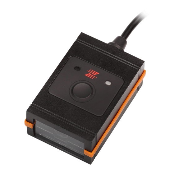
’ ANUAL Outline # Description Function 1 Trigger Button Push to scan 2 Speaker Exit For beep tone indication 3 LED Indicator For status indication 4 Scan Window Read barcodes 5 Tripod Socket For mounting the device on camera tripod 6 Mounting holes For mounting the device 2D Image Scan Module... -
Page 10: Installing The Device
’ ANUAL Installing the Device Using Mounting Screw The device is reserved with 3 mounting holes for permanent fixture if required. Refer to the figure below for detailed information. Unit: mm(inch) Mounting screw holes 2D Image Scan Module... -
Page 11: Connection
’ ANUAL Connection Power Connection The scanner turns on when power is supplied, and turns off when power is removed. There is no on/off switch on the scanner itself. The scanner requires a minimum of 2W at 5VDC power. The interface cable that comes with the scanner supports both direct power (where the scanner takes power from the host machine) and external power (that’s what the supplied power adapter is for). - Page 12 ’ ANUAL Follow the steps below when you need an external power connection to the scanner: Connect the interface cable to the bottom of the scanner. Connect the other end of the interface cable to the host (refer to your host manual to locate the correct port).
-
Page 13: Scanner Operation
’ ANUAL Scanner Operation Please follow the procedure below to verify scanning operation. If necessary, plug the power adapter into the jack on the interface cable. Plug the AC end of the power adapter into an AC outlet, or plug the other end of cable into host if power adapter is not needed. -
Page 14: Setting Up The Scanner
’ ANUAL Setting Up the Scanner In certain cases no setup is required. The scanner is either pre-programmed to suit the situation, or it automatically detects and is ready to go. In other cases the scanner must be informed about what kind of system it is connected to. This can be done in a few moments using the programming barcodes in the Programming Guide. -
Page 15: Programming The Scanner
’ ANUAL Programming the Scanner When the scanner is powered on (blue LED lights), find the <Set> barcode in the Programming Guide and present this barcode to the scanner. When the scanner gives two beeps, it means the scanner is in programming mode. Decide which parameters are required and find their barcodes in the Programming Guide. -
Page 16: How To Scan In Different Mode
’ ANUAL How to Scan in Different Mode Presentation Mode In this mode, the front scan window is in automatic mode and reads barcodes as the barcode approaches with the scanning field. Continue Scan Mode In this mode, the scan LED light stays active and continues to decode. If no barcode is present in the scanning field for 5 minutes, the scanner goes to standby with indicator LED continues to flash. -
Page 17: Manual Scan
’ ANUAL Manual Scan The scanner can also be used as a handheld scanner by simply pressing the button. Press down the trigger button and a light pattern would appear. It allows you to aim at the barcode. Trigger button Press the button to decode the barcode. -
Page 18: Sleep Mode
’ ANUAL Sleep Mode After the scanner has been inactive for a period of time, the scanner would enter the sleep mode. After 30 seconds inaction, the scanner would enter the sleep mode from presentation mode. After 5 minutes inaction, the scanner would enter the sleep mode from continue scan mode. -
Page 19: Beeper Indication
’ ANUAL Beeper Indication Beeps Indication 3 beeps in a series from low to high pitch Power up 1 short beep A barcode has been successfully decoded 2 short beeps The scanner has entered program mode 1 long beep A setting has been programmed 3 beeps in a series from low to high pitch The scanner has exited program mode 3 short beeps... -
Page 20: Usb Virtual Com
’ ANUAL USB Virtual COM If you use virtual COM port emulation, follow the steps below to start using the scanner. Execute the driver (VCOM-Driver-Installation.exe). Connect the scanner USB cable to the host computer. Set the interface to USB Virtual COM Port. Enable USB virtual COM 2D Image Scan Module... -
Page 21: Trouble Shooting
’ ANUAL On the computer, check Device Manager to see if the computer successfully detects the scanner as “Barcode Scanner USB-COM device.” (The COM port number would vary depending on different hardware environment). Trouble Shooting This section contains information about how to solve problems that you may encounter when operating the scanner. -
Page 22: Maintaining The Scanner
’ ANUAL Maintaining the Scanner Cleaning the Scan Window The scanner is designed for long-term trouble-free operation and rarely requires any maintenance. Only an occasional cleaning of the scanner window is necessary in order to remove dirt and fingerprints. Wipe the scan window with a soft lint-free cloth and a non-abrasive cleaner to avoid scratching and damaging the scan window. -
Page 23: Dimension
’ ANUAL Dimension Unit: mm 2D Image Scan Module... - Page 24 ’ ANUAL Specification Sensor Resolution 1280H × 800V pixels Light Source 2* 617nm LED (Red) Image Field of View (Scan Zone) 38.2°H x 24.3°V Roll/ Pitch/ Yaw 360°/ ± 65°/ ± 60° Scan Rate 60 fps Optical Print Contrast Ratio (Minimum) 30% @ UPC/EAN 100% Code 39 (5 mil): 55 - 150 mm UPC/EAN (13 mil): 55 - 265 mm Minimal Element Resolution...
-
Page 25: Connector And Pin Out
’ ANUAL Connector and Pin Out RS-232 interface (DTE Pinout) – Power adapter required if host can not provide sufficient power PIN-OUT CONFIGURATION PIN FUNCTION PIN FUNCTION N.C. N.C. +5V Input Inner of DC-Jack: +5V DC Outer of DC-Jack: GND USB /USB virtual COM / OPOS USB interface FUNCTION VBUS...
Need help?
Do you have a question about the Z-5652 and is the answer not in the manual?
Questions and answers