Table of Contents
Advertisement
Quick Links
Advertisement
Table of Contents

Related Manuals for FAAC J275 HA 2K20


Summary of Contents for FAAC J275 HA 2K20
- Page 1 J275 HA 2K20 Translation of the original instructions...
- Page 2 Nessuna parte di questo manuale può essere riprodotta, archiviata, distribuita a terzi né altrimenti copiata, in qualsiasi formato e con qualsiasi mezzo, sia esso elettronico, meccanico o tramite fotocopia, senza il preventivo consenso scritto di FAAC S.p.A. Tutti i nomi e i marchi citati sono di proprietà dei rispettivi fabbricanti.
-
Page 3: Table Of Contents
3. J275 HA 2K20 ........ -
Page 4: The Manufacturer
When drafting the manual, the results of the risk assessment con- WARNING ELECTRIC SHOCK HAZARD - The operation or stage described ducted by FAAC S.p.A. on the entire product life cycle have been taken must be performed following the supplied instructions and applicable into account in order to implement effective risk reduction measures. -
Page 5: Safety Recommendations
Use work instruments in good conditions. Use the transport and lifting equipment recommended in the instruc- tions manual. Use safety-compliant portable ladders of adequate size, fitted with anti-slip devices at the top and bottom, equipped with retainer hooks. J275 HA 2K20 532270 - Rev.A... -
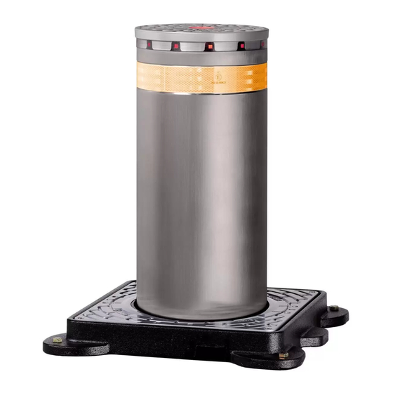
Page 6: J275 Ha 2K20
Sale code specified in the Technical Data and Installation Requirements Product name sections. MM/YY PROG IDENTIFICATION NUMBER - It is prohibited to use the J275 HA 2K20 in a configuration other •••••• •••• •••• Month/year of production + progressive •••• ••••... -
Page 7: Technical Characteristics
The cylinder is moved by an internal hydraulic unit. A release device, protected by a security lock, to lower the cylinder can be accessed from the top. The thrust capacitor is pre-wired and housed in the internal junction box. Certifications The J275 HA 2K20 bollard is certified according to the following standards and relative performance levels: - PAS 68:2013 V/7500 (N2)/48/90:1.7/0.0... -
Page 8: Optional Accessories
Hydraulic control unit protection rating IP67 See 4 Dimensions Thrust capacitor (pre-wired) 16 μF - 400V Continuous use time (ROT) 110 min at 23°C Load class (EN124) C250 (25 t) 3.8 DIMENSIONAL DRAWING Cover 3 4 J275 HA 2K20 532270 - Rev.A... -
Page 9: Installation Requirements
The foundation diagram is supplied with the pit and shows a double unit installation. For information about the foundation diagram for a multiple bollard configuration, please contact FAAC technical support. 4.2 ELECTRICAL SYSTEM Always shut off the power supply before performing any work. If the disconnect switch is not in view, apply a warning sign stating “WARN-... -
Page 10: Installation
Use belts or chains and a lifting device that are suitable for the weight of the bollard. Take care not to damage the electrical cable by pinching it between the frame and the pit. 8 J275 HA 2K20 532270 - Rev.A... -
Page 11: Manual Operation
To reposition or lift the cover, prise one of the two slots upwards using a screwdriver. 11 3. 12 Insert the key 1 and turn it anticlockwise until it stops 2. 1 0 12 J275 HA 2K20 532270 - Rev.A... -
Page 12: Restoring Automatic Operation
5. Actuate the release device by turning the knob anticlockwise. 16 5. 17 Put back the screws 2 and the plug 3. 6. Replace the plugs 1. 1 4 17 J275 HA 2K20 532270 - Rev.A... -
Page 13: Connections
LOWER limit switch UPPER limit switch Solenoid valve* Solenoid valve* +24V Lights Buzzer Pressure Switch Common* 12 13 11 Pressure Switch Signal* UPPER limit switch LOWER limit switch Communal limit switch * optional accessories 18 J275 HA 2K20 532270 - Rev.A... -
Page 14: Board Programming
After connecting and switching on the power to the control board as per the previous chapter, select the work pre-setting for the bollard J275 HA 2K20 by performing the following operation: 1. Access level 1 programming by holding down the F button on the board (1 9). - Page 15 10 s LAMP OUT 4 4 5 6 OUT 3 OUT 3 OUT 2 OUT 1 +24 V +24 V EMERGENCY STOP CLOSE OPEN A LOOP 2 LOOP 2 LOOP 1 LOOP 1 2 1 J275 HA 2K20 532270 - Rev.A...
-
Page 16: Troubleshooting
5 on the JE275 board (§ 5.4) The flashing LED light is not working Make sure that the power supply connector located under the head is plugged in correctly. Check the accessories fuse on the JE275 board. J275 HA 2K20 532270 - Rev.A... -
Page 17: Maintenance
2 3 Do not modify the original components in any way. FAAC S.p.A. disclaims any liability for damage caused by components 5. Completely remove the hydraulic unit from the bollard. that are modified or tampered with. ... -
Page 18: Topping Up The Oil Level
Check the drainage. Clean the sliding guides Make sure that there are no oil leaks Top up the oil level, if necessary. Only use FAAC oil Check the condition of the actuator cables, the cable glands and junc- tion boxes. -
Page 19: Installing Optional Equipment
OUT 4 OUT 3 OUT 3 OUT 2 OUT 1 +24 V +24 V Master JE275 board 35 Nm EMERGENCY STOP Violet Brown CLOSE 3 0 Blue Blue 28 J275 HA 2K20 532270 - Rev.A... -
Page 20: Installing The Solenoid Valve
Follow the connection diagrams below. MOT2 Rapid lowering MOT1 3 2 5. Install the control coil onto the solenoid valve. LAMP Standard lowering Mains voltage (230V) 3 5 3 3 J275 HA 2K20 532270 - Rev.A... -
Page 21: Multiple Connections
JE275 boards in a master / slave configuration, connect the coils to the inputs of the relative control board (master or slave) as indicated in the following diagram. Master JE275 board MOT2 MOT1 3 8 LAMP Slave JE275 board MOT2 MOT1 LAMP 3 7 J275 HA 2K20 532270 - Rev.A... -
Page 22: Faac S.p.a. Soc. Unipersonale
FAAC S.p.A. Soc. Unipersonale Via Calari, 10 - 40069 Zola Predosa - BOLOGNA - ITALY Tel. +39 051 61724 - Fax +39 051 09 57 820 www.faac.it - www.faacgroup.com J275 HA 2K20 532270 - Rev.A...
Need help?
Do you have a question about the J275 HA 2K20 and is the answer not in the manual?
Questions and answers