Table of Contents
Advertisement
Quick Links
Advertisement
Table of Contents

Related Manuals for FAAC J355 HA M50 EFO


Summary of Contents for FAAC J355 HA M50 EFO
- Page 1 J355HA M50 www.FastGateOpeners.com | (800) 878-7829 | Sales@FastGateOpeners.com...
-
Page 2: Table Of Contents
2.5 Insertion into the pit ..........11 6. FAAC declines all liability deriving from misuse or any use other than that for which the automated system is intended. -
Page 3: Bollard J355Ha M50
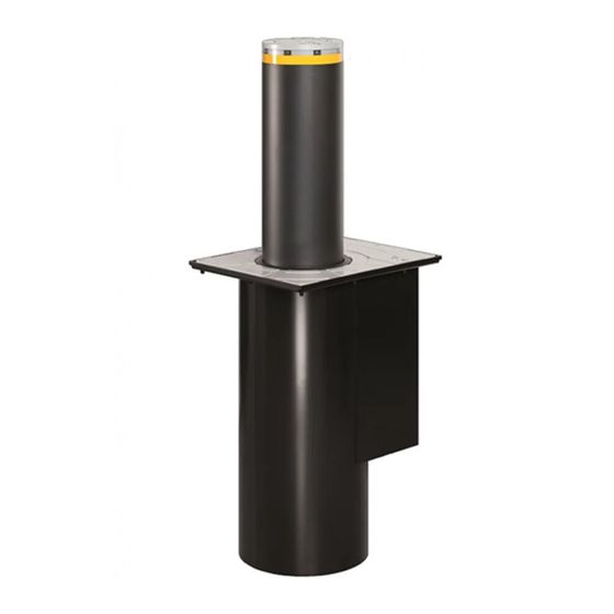
1. BOLLARD J355HA M50 Please read this manual carefully. It accompanies the product, providing important information regarding safety, installation and use. 1.1 GENERAL INSTRUCTIONS These instructions apply to the model J355HA M50 This model refers to automatic hydraulic counter-terrorism traffic bollards. The cylinder is moved by a hydraulic unit inside the structure. 1.2 TECHNICAL DESCRIPTIONS AND SPECIFICATIONS 1 Flashing LED 10 Cable guides... -
Page 4: Dimensions
1 Table A - Technical specifications (1) Check the oil level using the dipstick positioned under the filler cap (1-7) with the piston rod fully inside and the EFO MODEL J355HA M50 system under pressure. Power supply 230 V~ (+6% -10%) 50 (60) Hz (2) The starting capacitor (70μF - 400v) is pre-wired inside the junc-... -
Page 5: Installation
2. INSTALLATION 2.1 CONFIGURATION A flexible hose with a diameter of Ø100 mm should be fitted for drainage. Dig the hole to a depth of approximately 1.85 m IMPACT DIRECTION UNPROTECTED AREA PROTECTED AREA 3100 Excavation Ground Dimensions in mm 3 www.FastGateOpeners.com | (800) 878-7829 | Sales@FastGateOpeners.com... -
Page 6: Construction Of The Foundation Cage
2.2 CONSTRUCTION OF THE FOUNDATION CAGE Build the foundation cage (not supplied by FAAC) as shown in 4 using the Ø 12mm and Ø 20 mm iron rods - CLASS B450C 4 www.FastGateOpeners.com | (800) 878-7829 | Sales@FastGateOpeners.com... -
Page 7: Fixing The Pit In Place
2.3 FIXING THE PIT IN PLACE Once the foundation cage has been constructed, secure the counter- frame to the pit plate with the M10x25 screws (5). Then, position the pit inside the cage (6), and weld four 900 mm - Ø20mm (6-1) rods to the cage 5 Weld the rods (900mm - Ø... - Page 8 Whilst the concrete is curing, insert one or more of contrast supports inside the pit, to prevent the walls from bowing inwards due to the load of the fresh concrete. IMPACT DIRECTION UNPROTECTED AREA PROTECTED AREA Dimensions in mm 3100 Road surface Ground Flexible sheath Ø...
-
Page 9: Electrical Wiring
2.4 ELECTRICAL WIRING Any additional accessories (e.g. Open/close buttons, etc.) that are connected to the control board must be double insulated. To connect the bollard, use a multi-pole cable such as FG7OR-0.6/1kV- 16G1.5 (16 wires of 1.5mm2) between bollard and control board and a FG7OR-0.6/1kV-3G4 cable (3 wires of 4 mm2) for the motor power supply, both measuring a maximum of 50 metres in length. -
Page 10: Insertion Into The Pit
2.5 INSERTION INTO THE PIT After you have fully inserted the bollard, resting it against the coun- terframe, remove the two eye bolts 11-1 and fix the bollard in place Before inserting the bollard into the pit, complete the electrical using the 24 TCEI M24x50 screws supplied with the pit. -
Page 11: Efo (Emergency Fast Operation - Optional)
2.7 EFO (EMERGENCY FAST OPERATION - 2.10 MAINTENANCE OPTIONAL) The standard sequence of routine maintenance is as follows: The bollard J355HA M50 can be equipped with an EFO (Emergency Fast Operation) emergency activation system, which can be activated 1. Clean the pit by sucking out any deposited material at any time to raise the cylinder immediately. -
Page 12: Electronic Device Je275
3. ELECTRONIC EQUIPMENT JE275 Before performing any work on the electronic equipment (connections, maintenance), always turn the power off. Install a differential thermal breaker upstream with adequate tripping threshold (0.03A). Connect the ground cable to the terminal on the J9 connector on the equipment (14). Check that the mains switch is equipped with a locking key, unless this is fitted under the supervision of the operator/maintainer ... -
Page 13: Board Programming
3.2 BOARD PROGRAMMING After connecting and switching on the power to the control board as per the previous chapter, select the work pre-setting for the bollard J355HA M50 by performing the following operation: 1. Access level 1 programming by holding down the F button on the control board (15). -
Page 14: Connecting Several Bollards (Master/Slave)
3.4 CONNECTING SEVERAL BOLLARDS (MASTER/SLAVE) You can operatemore than one bollard simultaneously, and these can be interconnected using the corresponding JE275 device in the MASTER- SLAVE configuration. Follow the following guidelines for proper wiring and operation of the devices. JE275 MASTER JE275 SLAVE 10 s 10 s...
Need help?
Do you have a question about the J355 HA M50 EFO and is the answer not in the manual?
Questions and answers