Table of Contents
Advertisement
Quick Links
Lantech
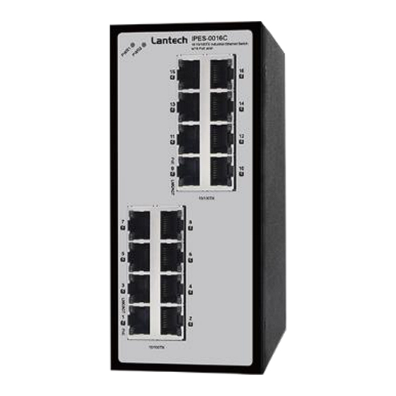
I(P)ES-0016C
16 10/100TX (PoE at/af) Industrial Unmanaged
Ethernet Switch
User Manual
V1.00
AUG. 2024
Notice
Only 24VDC input system is applicable for E-mark approval.
The unmanaged PoE Ethernet switch is equipped with P.S.E capacity. It is
designed for data communication within vehicles, to facilitate data transfer and
Ethernet connectivity as well as expandability. It's important to note that these
features have no impact on the safety of driving and passenger well-being and
the device does not possess any immunity-related functionalities.
Advertisement
Table of Contents

Related Manuals for Lantech IES-0016C


Summary of Contents for Lantech IES-0016C
- Page 1 Lantech I(P)ES-0016C 16 10/100TX (PoE at/af) Industrial Unmanaged Ethernet Switch User Manual V1.00 AUG. 2024 Notice Only 24VDC input system is applicable for E-mark approval. The unmanaged PoE Ethernet switch is equipped with P.S.E capacity. It is designed for data communication within vehicles, to facilitate data transfer and Ethernet connectivity as well as expandability.
-
Page 2: Approval Information
Approval Information Version 1.00 Name Title Date Author Greg Tsai Marketing 2024.08.08 Verifier Jacky Chou HW QA 2024.08.08 Approver Thomas Lee RD head 2024.08.08 Version Date Content of Modification Author(s) V1.00 2024.08.08 Greg Tsai... - Page 3 Recommendation for Shielded network cables STP cables have additional shielding material that is used to reduce external interference. The shield also reduces the emission at any point in the path of the cable. Our recommendation is to deploy an STP network cable in demanding electrical environments. Examples of demanding indoor environments are where the network cable is located in parallel with electrical mains supply cables or where large inductive loads such as motors or contactors are in close vicinity to the camera or its cable.
-
Page 4: Important Notice
Lantech Communications Global Inc. Products offered may contain software which is proprietary to Lantech Communications Global Inc. The offer or supply of these products and services does not include or infer any transfer of ownership. -
Page 5: Fcc Warning
FCC Warning This Equipment has been tested and found to comply with the limits for a Class-A digital device, pursuant to Part 15 of the FCC rules. These limits are designed to provide reasonable protection against harmful interference in a residential installation. This equipment generates, uses, and can radiate radio frequency energy. -
Page 6: Table Of Contents
Content Overview ............1 Introduction .............. 1 Model Lists ............... 1 Packing List .............. 2 Safety Precaution ............. 2 Hardware Description ......... 3 Front Panel ............... 4 Top View ..............5 Dimensions .............. 5 Wiring the Power Inputs ........... 6 Wiring the Ignition ............ - Page 7 DIN-Rail Mounting ..........12 Wall-Mount Plate Mounting ........14 Hardware Installation ........16 Installation Steps ............ 17 Troubleshooting ..........18...
-
Page 8: Overview
Overview Introduction The unmanaged industrial switch is a cost-effective solution and meets the high reliability requirements demanded by industrial applications. Model Lists Model name 10/100TX PoE ports ports IPES-0016C IES-0016C For latest product specifications, please refer to Lantech official site. -
Page 9: Packing List
Packing List ◼ 1 x 16-port Industrial Ethernet Switch ◼ 1 x Terminal Block Safety Precaution Attention If DC voltage is supplied by an external circuit, please use a protection device on the power supply input. -
Page 10: Hardware Description
For POE models: Do not use units' POE ports to uplink to another POE switch in vehicle applications. (May Cause Damage) Lantech strongly advise the installation of a Galvanic isolated DC/DC converter between the power supply and the Ethernet switch on all Non-Isolated models. -
Page 11: Front Panel
Front Panel The Front Panel of the IPES-0016C/IES-0016C is shown as below. Front Panel of the Industrial Switch... -
Page 12: Top View
Top View The top panel of the Industrial Switch is equipped one terminal block connector of two DC power inputs. Top panel of the Industrial Switch Converter Dimensions . The dimensions of the switch is 40 x 152 x 105 mm (W x H x D). The figure below gives the dimensions and views of each side of the 8-port Industrial Switch. -
Page 13: Wiring The Power Inputs
When the vehicle has been stalled by the driver, some equipment in the car may still need to run for a while. With Lantech ignition switch, even if the engine of the vehicle has been turned off by driver, the switch can still... -
Page 14: Ignition Poe Off Timer (Poe Model With Ignition)
Insert the wires into the ignition pin (No. 4) Note The wire gauge for the terminal block should be in the range between 12~ 24 AWG. Ignition PoE Off Timer (PoE model with ignition) The switch supports optional PoE feeding OFF timer (1/5/10mins or others) when vehicle main key is off to prevent car battery drain-out. -
Page 15: Grounding
Grounding Correctly connecting the grounding cable is crucial to surge, EST and EMI protection. -
Page 16: Led Indicators
LED Indicators The LED indicators located on the front panel display the power status and network status of the Industrial switch; each has their own specific meaning as the table shown below. Color Description Power input 1 is active Green Power input 1 is inactive Power input 2 is active Green... -
Page 17: Rj-45 Pin Assignments
RJ-45 Pin Assignments The UTP/STP ports will automatically sense for Fast Ethernet (10Base-T/100Base-TX) or Gigabit Ethernet (10Base-T/100Base-TX/1000Base-T) connection. Auto MDI/MDIX means that the switch can connect to another switch or workstation without changing straight through or crossover cabling. See the figures below for straight through and crossover cable schema. -
Page 18: Cabling
◼ 10/100Base-TX Cable Schema Straight Through Cable Schema Crossover Cable Schema Cabling Use unshielded twisted-pair (UTP) or shielded twisted-pair (STP) cable for RJ-45 connections: 100Ω Category 3, 4 or 5 cable for 10Mbps connections, or 100Ω Category 5 cable for 100Mbps connections. The cable between the switch and the link partner (switch, hub, workstation, etc.) must be less than 100 meters (328 ft.) long. -
Page 19: Mounting Installation
Mounting Installation DIN-Rail Mounting Assembling the DIN-Rail Clip The DIN-rail clip is screwed on the industrial switch when out of factory. If not, please refer to the following steps and figure to secure the DIN-rail clip on the switch. 1, Use the screws to screw on the DIN-rail clip on the industrial switch. 2, To remove the DIN-rail clip, reverse step 1. - Page 20 Hanging the Industrial Switch Follow the steps below to hang the industrial switch on the DIN rail. 1, First, position the rear side of the switch directly in front of the DIN rail. Make sure the top of the clip hooks over the top of the DIN rail. 2, Push the unit downward.
-
Page 21: Wall-Mount Plate Mounting
4, To remove the industrial switch from the track, reverse the steps above. Wall-Mount Plate Mounting Follow the steps below to mount the industrial switch with wall mount plate. 1. Remove the DIN-Rail from the industrial switch; loose the screws to remove the DIN-Rail. -
Page 23: Hardware Installation
Hardware Installation In this paragraph, we will describe how to install the 8-port 10/100TX Industrial Switch and the installation points for the attention. -
Page 24: Installation Steps
Installation Steps Unpacked the Industrial switch. Check the DIN-Rail is screwed on the Industrial switch. If the DIN-Rail is not screwed on the Industrial switch. Please refer to DIN-Rail Mounting section for DIN-Rail installation. If you want to wall mount the Industrial switch, then please refer to Wall-Mount Plate Mounting section for wall mount plate installation. -
Page 25: Troubleshooting
Troubleshooting ◼ Verify that you are using the included or appropriate power cord/adapter. Don’t use the power adapter with DC output higher than the power rating of the device. Otherwise, the device will burn down. ◼ Select the proper UTP/STP cable to construct your network. Please check that you are using the right cable.
Need help?
Do you have a question about the IES-0016C and is the answer not in the manual?
Questions and answers