
Subscribe to Our Youtube Channel
Related Manuals for Lantech IES-22812F-2P


Summary of Contents for Lantech IES-22812F-2P
- Page 1 Lantech IES-22812F-2P 12 100FX + 8 10/100TX + 2 1000 SFP Industrial Power Station L2 Plus Managed Switch User Manual V1.01 Nov-2010...
- Page 2 FCC Warning This Equipment has been tested and found to comply with the limits for a Class-A digital device, pursuant to Part 15 of the FCC rules. These limits are designed to provide reasonable protection against harmful interference in a residential installation. This equipment generates, uses, and can radiate radio frequency energy.
-
Page 3: Table Of Contents
Content Chapter 1 Introduction..........1 Hardware Features ...........1 Software Features .............2 Package Contents .............4 Chapter 2 Hardware Description ......5 Physical Dimensions ..........5 Front (LED) Panel .............5 Rear Panel ..............6 LED Indicators............7 Chapter 3 Hardware Installation ......9 Rack-mounted Installation.........9 Cabling ..............11 Wiring the Power Inputs ..........14 Wiring the P-Fail Alarm Contact ......15... - Page 4 Commands Level ............22 Chapter 6 Web-Based Management ..... 24 About Web-based Management ......24 Preparing for Web Management ......24 System Login............25 System Information ..........26 IP Configuration ............27 DHCP Server ............28 6.6.1 System configuration ..........29 6.6.2 Client Entries............30 6.6.3 Port and IP Bindings ..........31 TFTP ...............32 6.7.1 Update Firmware ............32...
- Page 5 6.13.3 Jumbo Frame ............52 6.14 Port Statistics ............53 6.15 Port Counters ............55 6.16 Port Control .............58 6.17 Port Trunk..............60 6.17.1. Aggregator setting ..........60 6.17.2. Aggregator Information..........62 6.17.3. State Activity............66 6.18 Port Mirroring............68 6.19 Rate Limiting ............69 6.20 VLAN configuration ..........70 6.20.1.
- Page 6 6.27.3. Misc Configuration..........98 6.28 MAC Address Table ..........100 6.28.1. Static MAC Address ..........100 6.28.2. MAC Filtering............102 6.28.3. All MAC Addresses ..........103 6.28.4. MAC Address Table—Multicast Filtering.....104 6.29 Access Control List ..........106 6.30 Factory Default ............107 6.31 Save Configuration..........108 6.32 System Reboot............109 Troubleshooting ...........
- Page 7 SNTP Commands Set ............142 Pro-Ring Commands Set...........144 LLDP Command Set ............145 Access Control List Command Set........146...
-
Page 8: Chapter 1 Introduction
Chapter 1 Introduction The 8 10/100TX + 12 100FX + 2 Gigabit Mini-GBIC Managed Industrial Switch is a cost-effective solution and meets the high reliability requirements demanded by industrial applications. The 8 10/100TX + 12 100FX + 2 Gigabit Mini-GBIC Managed Industrial Switch can be easily managed through the Web GUI. -
Page 9: Software Features
R.Master (Green) Port1~22 : Link/Activity (Green), Port13~20: Full-duplex (Amber) Reverse Polarity Present Protection Overload Current Present Protection IES-22812F-2P: 100~240V Power Supply AC/DC Power IES-22812F-2P: 27.6 Watts max. @ 110 V Consumption 26.2 Watts max. @ 110 V 5% to 95% (Non-condensing) - Page 10 Spanning Tree Support IEEE802.1w Rapid Spanning Tree Pro-Ring Support X-Ring, Dual Homing, Couple Ring Topology. Provide redundant backup feature and the recovery time below 10ms. Quality of Service The quality of service determined by port, Tag and IPv4 Type of service, IPv4 Different Service Class of Service Support IEEE802.1p class of service, per port provides 4 priority queues...
-
Page 11: Package Contents
Download ifAlias Each port allows an alphabetic string of 128-byte assigned as its own unique name via the CLI or SNMP interface. 1.3 Package Contents Please refer to the package content list below to verify them against the checklist. 12 100FX + 8 10/100TX + 2 1000 SFP Industrial Power Station L2+ Managed Switch x 1 User manual x 1 Mounting plate x 2 RJ-45 to DB9-Female cable x 1... -
Page 12: Chapter 2 Hardware Description
Chapter 2 Hardware Description In this paragraph, we will describe the Industrial switch’s hardware spec, port, cabling information, and wiring installation. 2.1 Physical Dimensions 12 100FX + 8 10/100TX + 2 1000 SFP Industrial Power Station L2+ Managed Switch dimensions (W x H x D) are 440mm x 44mm x 280mm as the figure shown below. Mechanical Dimensions 2.2 Front (LED) Panel The figure below illustrates the front panel of the 12 100FX + 8 10/100TX + 2 1000 SFP... -
Page 13: Rear Panel
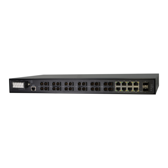
2.3 Rear Panel The 12 fiber ports, 8 copper ports, 2 SFP ports, console port and terminal block are located on the rear panel of the Managed Industrial Switch. Front Panel of the industrial switch... -
Page 14: Led Indicators
2.4 LED Indicators The diagnostic LED indicators located on the front panel & rear panel of the industrial switch provide real-time information of the system and optional status. The following table provides description of the LED status and their meanings for the switch. Front Panel Color Status... - Page 15 Rear Panel Color Status Meaning The switch is the MASTER device of the X-Ring group R.M. Green The switch is not the MASTER device of the X-Ring group Power1 is inactive Power2 is inactive Port Link-down P-Fail Port Link-broken No failure occurs Power 1 is active Green Power 1 is inactive...
-
Page 16: Chapter 3 Hardware Installation
Chapter 3 Hardware Installation 3.1 Rack-mounted Installation The 12 100FX + 8 10/100TX + 2 1000 SFP Industrial Power Station L2+ Managed Switch comes with a rack-mounted kit and can be mounted in an EIA standard size, 19-inch Rack. The Switch can be placed in a wiring closet with other equipment. Perform the following steps to rack mount the switch: Position one bracket to align with the holes on one side of the switch and secure it with the smaller bracket screws. - Page 17 Figure 2-5. Mount the Switch in 19” Rack Note: For proper ventilation, allows about at least 4 inches (10 cm) of clearance on the front and 3.4 inches (8 cm) on the back of the Switch. This is especially important for enclosed rack installation.
-
Page 18: Cabling
3.2 Cabling Twisted-pair segment can be established by using unshielded twisted pair (UTP) or shielded twisted pair (STP) cabling. The cable between the link partner (switch, hub, workstation, etc.) and the switch must be less than 100 meters (328 ft.) long and comply with the IEEE 802.3ab 1000Base-T standard for Category 5e or above. - Page 19 Transceiver Inserted Second, insert the fiber cable of LC connector into the transceiver. LC connector to the transceiver...
- Page 20 To remove the LC connector from the transceiver, please follow the steps shown below: First, press the upper side of the LC connector from the transceiver and pull it out to release. Remove LC connector Second, push down the metal loop and pull the transceiver out by the plastic part. Transceiver pulled out from the SFP slot...
-
Page 21: Wiring The Power Inputs
3.3 Wiring the Power Inputs Please follow the steps below to insert the power wires. IES-22812F-2P power inputs wiring 1. Attach AC or DC power wires to the contacts. Power 1: Pin 1 (-), Pin 3 (+) for DC power source... -
Page 22: Wiring The P-Fail Alarm Contact
3.4 Wiring the P-Fail Alarm Contact Attach the wires to form a Normally Close circuit. When power or network linking failure occurs, the system will break the circuit to Open status. Please refer to the figure illustrated below. IES-22812F-2P P-Fail Alarm connectors... -
Page 23: Chapter 4 Network Application
Chapter 4 Network Application This chapter provides some sample applications to help the user to have more actual idea of industrial switch function application. A sample application of the industrial switch is shown as below:... -
Page 24: X-Ring Application
4.1 X-Ring Application The industrial switch supports the X-Ring protocol that can help the network system to recover from network connection failure within 20ms or less, and make the network system more reliable. The X-Ring algorithm is similar to Spanning Tree Protocol (STP) and Rapid STP (RSTP) algorithm but its recovery time is less than STP/RSTP. -
Page 25: Coupling Ring Application
4.2 Coupling Ring Application In the network, it may have more than one X-Ring group. Using the coupling ring function can connect each X-Ring for the redundant backup. It can ensure the transmissions between two ring groups not to fail. The following figure is a sample of coupling ring application. -
Page 26: Dual Homing Application
4.3 Dual Homing Application Dual Homing function is to prevent the connection loss from between X-Ring group and upper level/core switch. Assign two ports to be the Dual Homing port that is backup port in the X-Ring group. The Dual Homing function only works when the X- Ring function is active. -
Page 27: Chapter 5 Console Management
Chapter 5 Console Management 5.1 Connecting to the Console Port The supplied cable which one end is RS-232 connector and the other end is RJ-45 connector. Attach the end of RS-232 connector to PC or terminal and the other end of RJ-45 connector to the console port of the switch. -
Page 28: Login In The Console Interface
5.3 Login in the Console Interface When the connection between Switch and PC is ready, turn on the PC and run a terminal emulation program or Hyper Terminal and configure its communication parameters to match the following default characteristics of the console port: Baud Rate: 9600 bps Data Bits: 8 Parity: none... -
Page 29: Cli Management
Console login interface 5.4 CLI Management The system supports the console management—CLI command. After you log in on to the system, you will see a command prompt. To enter CLI management interface, type in “enable” command. CLI command interface The following table lists the CLI commands and description. 5.5 Commands Level Access Exit... - Page 30 information. The privileged Enter the command is the enable Enter advanced mode. Privileged command switch# disable to Use this mode to EXEC while in User exit. • Display advanced EXEC mode. function status • Save configuration Enter the To exit to Use this mode to configure privileged...
-
Page 31: Chapter 6 Web-Based Management
Chapter 6 Web-Based Management This section introduces the configuration and functions of the Web-Based management. 6.1 About Web-based Management There is an embedded HTML web site residing in flash memory on CPU board of the switch, which offers advanced management features and allows users to manage the switch from anywhere on the network through a standard browser such as Microsoft Internet Explorer. -
Page 32: System Login
6.3 System Login Launch the Internet Explorer on the PC Key in “http:// “+” the IP address of the switch”, and then Press “Enter”. The login screen will appear right after Key in the user name and password. The default user name and password are the same as ‘root’. -
Page 33: System Information
6.4 System Information User can assign the system name, description, location and contact personnel to identify the switch. The version table below is a read-only field to show the basic information of the switch. System Name: Assign the system name of the switch (The maximum length is 64 bytes) System Description: Describes the switch. -
Page 34: Ip Configuration
6.5 IP Configuration The switch is a network device which needs to be assigned an IP address for being identified on the network. Users have to decide a means of assigning IP address to the switch. DHCP Client: Enable or disable the DHCP client function. When DHCP client function is enabled, the switch will be assigned an IP address from the network DHCP server. -
Page 35: Dhcp Server
IP configuration interface 6.6 DHCP Server DHCP is the abbreviation of Dynamic Host Configuration Protocol that is a protocol for assigning dynamic IP addresses to devices on a network. With dynamic addressing, a device can have a different IP address every time it connects to the network. In some systems, the device's IP address can even change while it is still connected. -
Page 36: System Configuration
6.6.1 System configuration DHCP Server: Enable or Disable the DHCP Server function. Enable—the switch will be the DHCP server on your local network. Low IP Address: Type in an IP address. Low IP address is the beginning of the dynamic IP range. For example, dynamic IP is in the range between 192.168.16.100 ~ 192.168.16.200. -
Page 37: Client Entries
6.6.2 Client Entries When the DHCP server function is enabled, the system will collect the DHCP client information including the assigned IP address, the MAC address of the client device, the IP assigning type, status and lease time. DHCP Client Entries interface... -
Page 38: Port And Ip Bindings
6.6.3 Port and IP Bindings Assign the dynamic IP address bound with the port to the connected client. The user is allowed to fill each port column with one particular IP address. When the device is connecting to the port and asks for IP assigning, the system will assign the IP address bound with the port. -
Page 39: Tftp
6.7 TFTP It provides the functions allowing the user to update the switch firmware via the Trivial File Transfer Protocol (TFTP) server. Before updating, make sure the TFTP server is ready and the firmware image is located on the TFTP server. 6.7.1 Update Firmware TFTP Server IP Address: Type in your TFTP server IP. -
Page 40: Restore Configuration
6.7.2 Restore Configuration You can restore a previous backup configuration from the TFTP server to recover the settings. Before doing that, you must locate the image file on the TFTP server first and the switch will download back the flash image. TFTP Server IP Address: Type in the TFTP server IP. -
Page 41: Backup Configuration
6.7.3 Backup Configuration You can back up the current configuration from flash ROM to the TFTP server for the purpose of recovering the configuration later. It helps you to avoid wasting time on configuring the settings by backing up the configuration. TFTP Server IP Address: Type in the TFTP server IP. -
Page 42: System Event Log
6.8 System Event Log This page allows the user to decide whether to send the system event log, and select the mode which the system event log will be sent to client only, server only, or both client and server. What kind of event log will be issued to the client/server depends on the selection on the Event Configuration tab. - Page 43 Syslog Configuration interface...
-
Page 44: System Event Log-Smtp Configuration
6.8.2 System Event Log—SMTP Configuration Simple Mail Transfer Protocol (SMTP) is the standard for email transmissions across the network. You can configure the SMTP server IP, mail subject, sender, mail account, password, and the recipient email addresses which the e-mail alert will send to. - Page 45 SMTP Configuration interface...
-
Page 46: System Event Log-Event Configuration
6.8.3 System Event Log—Event Configuration Having ticked the Syslog/SMTP checkboxes, the event log/email alert will be sent to the system log server and the SMTP server respectively. Also, Port event log/alert (link up, link down, and both) can be sent to the system log server/SMTP server respectively by setting the trigger condition. - Page 47 event of port occurs. Link UP & Link Down: The system will issue a log message at the time when port connection is link-up and link-down. Event Configuration interface...
-
Page 48: Fault Relay Alarm
6.9 Fault Relay Alarm The Fault Relay Alarm function provides the Power Failure and Port Link Down/Broken detection. With both power input 1 and power input 2 installed and the checkboxes of power 1/power 2 ticked, the P-Fail LED indicator will then be possible to light up when any one of the power failures occurs. -
Page 49: Sntp Configuration
6.10 SNTP Configuration SNTP (Simple Network Time Protocol) is a simplified version of NTP which is an Internet protocol used to synchronize the clocks of computers to some time reference. Because time usually just advances, the time on different node stations will be different. - Page 50 AST - Atlantic Standard -4 hours 8 am EDT - Eastern Daylight EST - Eastern Standard -5 hours 7 am CDT - Central Daylight CST - Central Standard -6 hours 6 am MDT - Mountain Daylight MST - Mountain Standard -7 hours 5 am PDT - Pacific Daylight...
- Page 51 WAST - West Australian +7 hours 7 pm Standard CCT - China Coast, +8 hours 8 pm USSR Zone 7 JST - Japan Standard, +9 hours 9 pm USSR Zone 8 EAST - East Australian Standard GST +10 hours 10 pm Guam Standard, USSR Zone 9 IDLE - International Date...
- Page 52 Click to have the configuration take effect. Apply SNTP Configuration interface...
-
Page 53: Ip Security
6.11 IP Security IP security function allows the user to assign 10 specific IP addresses that have permission to manage the switch through the http and telnet services for the securing switch management. The purpose of giving the limited IP addresses permission is to allow only the authorized personnel/device can do the management task on the switch. - Page 54 IP Security interface...
-
Page 55: User Authentication
6.12 User Authentication Change web management login user name and password for the management security issue. User name: Type in the new user name (The default is ‘root’) Password: Type in the new password (The default is ‘root’) Confirm password: Re-type the new password And then, click Apply User Authentication interface... -
Page 56: Advanced Configuration
6.13 Advanced Configuration This page enables the user to select the filter packet type including Flooded Unicast/Multicast Packets, Control Packets, IP Multicast Packets, and Broadcast Packets for the purpose of limiting the network bandwidth not being occupied by those storm-like packets. All the packet type filtering conditions can be active at the same time. - Page 57 Broadcast Packets: Having ticked this checkbox, the switch will filter the broadcast packets in accordance with the filter rate set in the Broadcast Storm Rate selection item. Broadcast Storm Filter interface...
-
Page 58: Aging Time
6.13.2 Aging Time When the MAC address table is full, it won’t learn the MAC address any more. Therefore, the aging time function allows users to set aging time in seconds for each record. Once the aging time of the record matches the setting, the record (dynamic MAC address) will be removed from the MAC table. -
Page 59: Jumbo Frame
6.13.3 Jumbo Frame Jumbo Frames are Ethernet frames with more than 1522 bytes of payload. Conventionally, jumbo frames can carry up to 9022 bytes of payload. Many, but not all, gigabit Ethernet switches and gigabit Ethernet network interface cards support jumbo frames, but all fast Ethernet switches/network interface cards support only standard- sized frames. -
Page 60: Port Statistics
6.14 Port Statistics The following chart provides the current statistic information which displays the real- time packet transfer status for each port. The user might use the information to plan and implement the network, or check and find the problem when the collision or heavy traffic occurs. - Page 61 Port Statistics interface...
-
Page 62: Port Counters
6.15 Port Counters This chart displays the transmitted and received traffic of single port. Select Port: Pull down the menu bar to select a particular port, and then the counters for the port will be displayed. RxBcastPkt: The number of good broadcast packets received. RxOctel: The number of octels of data received (including those in bad packet, excluding framing bits but including FCS octels, excluding RxPausePkt). - Page 63 RxFragment: The number of packets received that were less than 64 octels long and had a bad FCS or RX_ER asserted. RxUndersizePkt: The number of packets received that were less than 64 octels long and were otherwise well formed. RxPkt64: The number of packets received that were 64 octels in length including bad packets but excluding RxPausePkt.
- Page 64 TxUnderrun: The number of packets dropped because the output FIFO underrun. Click Clear to reset the figures.
-
Page 65: Port Control
6.16 Port Control In Port control you can configure the settings of each port to control the connection parameters, and the status of each port is listed beneath. Port: Use the scroll bar and click on the port number to choose the port to be configured. - Page 66 Port Control interface...
-
Page 67: Port Trunk
6.17 Port Trunk Port trunking is the combination of several ports or network cables to expand the connection speed beyond the limits of any one single port or network cable. Link Aggregation Control Protocol (LACP), which is a protocol running on layer 2, provides a standardized means in accordance with IEEE 802.3ad to bundle several physical ports together to form a single logical channel. - Page 68 the right side will be shifted to the left side. To remove unwanted ports, select the ports and click Remove When LACP enabled, you can configure LACP Active/Passive status for each port on the State Activity tab. Click Apply Delete to delete Trunk Group.
-
Page 69: Aggregator Information
6.17.2. Aggregator Information LACP disabled Having set up the aggregator setting with LACP disabled, you will see the local static trunk group information on the tab of Aggregator Information. Assigning 2 ports to a trunk group with LACP disabled Static Trunking Group information Group Key: This is a read-only column field that displays the trunk group ID. - Page 70 LACP enabled Having set up the aggregator setting with LACP enabled, you will see the trunking group information between two switches on the tab of Aggregator Information. Switch 1 configuration Set System Priority of the trunk group. The default is 1. Select a trunk group ID by pull down the drop-down menu bar.
- Page 71 Aggregation Information of Switch 1 Click on the tab of Aggregator Information to check the trunked group information as the illustration shown above after the two switches configured.
- Page 72 Switch 2 configuration Switch 2 configuration interface Set System Priority of the trunk group. The default is 1. Select a trunk group ID by pull down the drop-down menu bar. Enable LACP. Include the member ports by clicking the Add button after selecting the port number and the column field of Work Ports changes automatically.
-
Page 73: State Activity
6.17.3. State Activity Having set up the LACP aggregator on the tab of Aggregator Setting, you can configure the state activity for the members of the LACP trunk group. You can tick or cancel the checkbox beside the state label. When you remove the tick mark of the port and click , the port state activity will change to Passive. - Page 74 State Activity of Switch 2...
-
Page 75: Port Mirroring
6.18 Port Mirroring The Port mirroring is a method for monitoring traffic in switched networks. Traffic through ports can be monitored by one specific port, which means traffic goes in or out Monitored (source) port will be duplicated into Analysis (destination) port. Port Trunk –... -
Page 76: Rate Limiting
6.19 Rate Limiting All the ports support port ingress and egress rate control. The switch performs the ingress/egress rate by packet counter to meet the specified rate. When the traffic exceeds the limited transfer rate, the packets will be delayed or dropped. Rate Limiting interface Ingress: Assign the port effective ingress rate (The default value is “0”). -
Page 77: Vlan Configuration
6.20 VLAN configuration A Virtual LAN (VLAN) is a logical network grouping that limits the broadcast domain, which would allow you to isolate network traffic, so only the members of the same VLAN will receive traffic from the ones of the same VLAN. Basically, creating a VLAN on a switch is logically equivalent of reconnecting a group of network devices to another Layer 2 switch. - Page 78 VLAN – Port Based interface Pull down the selection item and focus on Port Based then press Apply to set the VLAN Operation Mode in Port Based mode. Click to add a new VLAN group (The maximum VLAN groups are up to 64).
- Page 79 VLAN—Port Based Add interface Enter the group name and VLAN ID. Add the selected port number into the right field to group these members to be a VLAN group, or remove any of them listed in the right field from the VLAN. And then, click to have the configuration take effect.
- Page 80 VLAN—Port Based Edit/Delete interface to delete the VLAN. Delete to modify group name, VLAN ID, or add/remove the members of the Edit existing VLAN group. [NOTE] Remember to execute the “Save Configuration” action, otherwise the new configuration will lose when switch power off.
-
Page 81: Q Vlan
6.20.2. 802.1Q VLAN Virtual Local Area Network (VLAN) can be implemented on the switch to logically create different broadcast domain. When the 802.1Q VLAN function is enabled, all ports on the switch belong to default VLAN of VID 1, which means they logically are regarded as members of the same broadcast domain. - Page 82 802.1Q Configuration Pull down the selection item and focus on 802.1Q then press Apply to set the VLAN Operation Mode in 802.1Q mode. Enable GVRP Protocol: GVRP (GARP VLAN Registration Protocol) is a protocol that facilitates control of virtual local area networks (VLANs) within a larger network.
- Page 83 Trunk Link: A segment which provides the link path for one or more VLAN- aware devices (switches). A Trunk Port, connected to the trunk link, has an understanding of tagged frame, which is used for the communication among VLANs across switches. Which frames of the specified VIDs will be forwarded depends on the values filled in the Tagged VID column field.
- Page 84 802.1Q VLAN interface Group Configuration Edit the existing VLAN Group. Select the VLAN group in the table list. Click Edit...
- Page 85 Group Configuration interface You can modify the VLAN group name and VLAN ID. Group Configuration interface Click Apply...
-
Page 86: Rapid Spanning Tree
6.21 Rapid Spanning Tree The Rapid Spanning Tree Protocol (RSTP) is an evolution of the Spanning Tree Protocol and provides for faster spanning tree convergence after a topology change. The system also supports STP and the system will auto-detect the connected device that is running STP or RSTP protocol. - Page 87 RSTP System Configuration interface...
-
Page 88: Port Configuration
6.21.2. Port Configuration This web page provides the port configuration interface for RSTP. You can assign higher or lower priority to each port. Rapid spanning tree will have the port with the higher priority in forwarding state and block other ports to make certain that there is no loop in the LAN. - Page 89 RSTP Port Configuration interface...
-
Page 90: Snmp Configuration
6.22 SNMP Configuration Simple Network Management Protocol (SNMP) is the protocol developed to manage nodes (servers, workstations, routers, switches and hubs etc.) on an IP network. SNMP enables network administrators to manage network performance, find and solve network problems, and plan for network growth. Network management systems learn of problems by receiving traps or change notices from network devices implementing SNMP. - Page 91 SNMP System Configuration interface...
-
Page 92: Trap Configuration
6.22.2. Trap Configuration A trap manager is a management station that receives the trap messages generated by the switch. If no trap manager is defined, no traps will be issued. To define a management station as a trap manager, assign an IP address, enter the SNMP community strings, and select the SNMP trap version. -
Page 93: Snmpv3 Configuration
6.22.3. SNMPV3 Configuration Configure the SNMP V3 function. Context Table Configure SNMP v3 context table. Assign the context name of context table. Click to add context name. Click to remove the unwanted context name. Remove User Table Configure SNMP v3 user table.. User ID: Set up the user name. - Page 94 SNMP V3 configuration interface Group Table Configure SNMP v3 group table. Security Name (User ID): Assign the user name that you have set up in user table. Group Name: Set up the group name. Click to add the context name. Click Remove to remove the unwanted context name.
- Page 95 Access Table Configure SNMP v3 access table. Context Prefix: Set up the context name. Group Name: Set up the group. Security Level: Set up the access level. Context Match Rule: Select the context match rule. Read View Name: Set up the read view. Write View Name: Set up the write view.
-
Page 96: Qos Configuration
6.23 QoS Configuration Quality of Service (QoS) is the ability to provide different priority to different applications, users or data flows, or to guarantee a certain level of performance to a data flow. QoS guarantees are important if the network capacity is insufficient, especially for real-time streaming multimedia applications such as voice over IP or Video Teleconferencing, since these often require fixed bit rate and are delay sensitive, and in networks where the capacity is a limited resource, for example in... - Page 97 TOS level 25 is set as 0 and each port only follows the TOS priority policy. When the packet received through all the ports on the switch, the system will check the TOS value of the received IP packet. If the TOS value of received IP packet is 25 (priority = 0), the packet priority has the highest priority.
-
Page 98: Igmp Configuration
6.24 IGMP Configuration The Internet Group Management Protocol (IGMP) is an internal protocol of the Internet Protocol (IP) suite. IP manages multicast traffic by using switches, routers, and hosts that support IGMP. Enabling IGMP allows the ports to detect IGMP queries, report packets, and manage IP multicast traffic through the switch. - Page 99 time. Click Apply IGMP Configuration interface...
-
Page 100: Pro-Ring
6.25 Pro-Ring X-Ring provides a faster redundant recovery than Spanning Tree topology. The action is similar to STP or RSTP, but the algorithms between them are not the same. In the X-Ring topology, every switch should be enabled with X-Ring function and two ports should be assigned as the member ports in the ring. - Page 101 the 2 Ring Port to be the working port. Enable Couple Ring: To enable the coupe ring function, tick the checkbox beside the Enable Couple Ring string label. Couple Port: Assign the member port which is connected to the other ring group.
-
Page 102: Lldp Configuration
6.26 LLDP Configuration ink Layer Discovery Protocol (LLDP) is defined in the IEEE 802.1AB, it is an emerging standard which provides a solution for the configuration issues caused by expanding LANs. LLDP specifically defines a standard method for Ethernet network devices such as switches, routers and wireless LAN access points to advertise information about themselves to other nodes on the network and store the information they discover. -
Page 103: Security-802.1X/Radius Configuration
6.27 Security—802.1X/Radius Configuration 802.1x is an IEEE authentication specification which prevents the client from accessing a wireless access point or wired switch until it provides authority, like the user name and password that are verified by an authentication server (such as RADIUS server). -
Page 104: Port Configuration
6.27.2. Port Configuration You can configure the 802.1x authentication state for each port. The state provides Disable, Accept, Reject, and Authorize. Reject: The specified port is required to be held in the unauthorized state. Accept: The specified port is required to be held in the authorized state. Authorize: The specified port is set to the Authorized or Unauthorized state in accordance with the outcome of an authentication exchange between the Supplicant and the authentication server. -
Page 105: Misc Configuration
802.1x Per Port Setting interface 6.27.3. Misc Configuration Quiet Period: Set the period which the port doesn’t try to acquire a supplicant. TX Period: Set the period the port waits for retransmit next EAPOL PDU during an authentication session. Supplicant Timeout: Set the period of time the switch waits for a supplicant response to an EAP request. - Page 106 an authentication request. Max Requests: Set the number of authentication that must time-out before authentication fails and the authentication session ends. Reauth period: Set the period of time which clients connected must be re- authenticated. Click Apply 802.1x Misc Configuration interface...
-
Page 107: Mac Address Table
6.28 MAC Address Table Use the MAC address table to ensure the port security. 6.28.1. Static MAC Address You can add a static MAC address that remains in the switch's address table regardless of whether the device is physically connected to the switch. This saves the switch from having to re-learn a device's MAC address when the disconnected or powered-off device is active on the network again. - Page 108 Static MAC Addresses interface...
-
Page 109: Mac Filtering
6.28.2. MAC Filtering By filtering MAC address with VLAN ID, the switch will drop the packet when both its destination MAC address and VLAN ID meet the condition configured in the MAC Filtering table. You can add and delete the MAC filters. MAC Filtering interface MAC Address: Enter the MAC address that you want to filter. -
Page 110: All Mac Addresses
6.28.3. All MAC Addresses You can view all of the MAC addresses learned by the selected port. This interface shows the MAC addresses information group by port. Port No.: Select the port number to view its MAC address. Current MAC Address: The static & dynamic MAC address information of the selected port will be displayed in here. -
Page 111: Mac Address Table-Multicast Filtering
6.28.4. MAC Address Table—Multicast Filtering Multicasts are similar to broadcasts, they are sent to all end stations on a LAN or VLAN. Multicast filtering is the function, which end stations can receive the multicast traffic if the connected ports had been included in the specific multicast groups. With multicast filtering, network devices only forward multicast traffic to the ports that are connected to the registered end stations. - Page 112 Multicast Filtering interface...
-
Page 113: Access Control List
6.29 Access Control List Group Id: Type in the Group ID from 1 to 255. Action: Permit and Deny. VLAN: Select any or a particular VID. Packet type: Select packet type—IPv4 or Non-IPv4 Src IP Address: Select any or assign an IP address with Subnet Mask for source IP address. -
Page 114: Factory Default
6.30 Factory Default Reset switch to default configuration. Click Reset to reset all configurations to the default value. Factory Default interface... -
Page 115: Save Configuration
6.31 Save Configuration Save all configurations that you have made in the system. To ensure the all configuration will be saved. Click to save the all configuration to the flash Save memory. Save Configuration interface... -
Page 116: System Reboot
6.32 System Reboot Reboot the switch in software reset. Click Reboot to reboot the system. System Reboot interface... -
Page 117: Troubleshooting
Troubleshooting Verify that you are using the right power cord/adapter. The power output of the adapter can’t be higher than the power rating of the equipment. Otherwise, the equipment will burn down. Select the proper UTP/STP cable to construct the user network. Use unshielded twisted-pair (UTP) or shield twisted-pair (STP) cable for RJ-45 connections that depend on the connector type the switch equipped: 100Ω... -
Page 118: Appendix A - Rj-45 Pin Assignment
Appendix A — RJ-45 Pin Assignment RJ-45 ports The UTP/STP ports will automatically sense for Fast Ethernet (10Base-T/100Base-TX connections), or Gigabit Ethernet (10Base-T/100Base-TX/1000Base-T connections). Auto MDI/MDIX means that the switch can connect to another switch or workstation without changing straight through or crossover cabling. See the figures below for straight through and crossover cable schematic. - Page 119 10/100Base-TX Cable Schematic The following two figures show the 10/100Base-TX cable schematic. Straight-through cable schematic Cross over cable schematic 10/100/1000Base-TX Pin outs The following figure shows the 10/100/1000 Ethernet RJ-45 pin outs.
- Page 120 10/100/1000Base-TX Cable Schematic Straight through cables schematic Cross over cables schematic...
-
Page 121: Appendix B - Command Sets
Appendix B — Command Sets Commands Set List User EXEC Privileged EXEC Global configuration VLAN database Interface configuration System Commands Set Commands Level Description Example show config Show switch switch>show config configuration show terminal Show console switch#show terminal information write memory Save user switch#write memory configuration into... - Page 122 [Ip-address] [Subnet- address of switch 192.168.1.1 255.255.255.0 mask] [Gateway] 192.168.1.254 ip dhcp Enable DHCP client switch(config)#ip dhcp function of switch show ip Show IP information of switch#show ip switch no ip dhcp Disable DHCP client switch(config)#no ip dhcp function of switch reload Halt and perform a cold switch(config)#reload...
- Page 123 dhcpserver ipbinding Set static IP for DHCP switch(config)#interface [IP address] clients by port fastEthernet 2 switch(config-if)#dhcpserver ipbinding 192.168.1.1 show dhcpserver Show configuration of switch#show dhcpserver configuration DHCP server configuration show dhcpserver Show client entries of switch#show dhcpserver clinets clients DHCP server show dhcpserver ip- Show IP-Binding switch#show dhcpserver ip-...
- Page 124 multicast Unicast/Multicast unicast-multicast Packets BSF bsf control Enable Control switch(config)#bsf control Packets BSF bsf ip-multicast Enable IP Multicast switch(config)#bsf ip-multicast Packets BSF bsf broadcast Packets BSF switch(config)#bsf broadcast no bsf flooded-unicast- Disable Flooded switch(config)#no bsf flooded- multicast Unicast/Multicast unicast-multicast Packets BSF no bsf control Disable Control switch(config)#no bsf control...
-
Page 125: Port Commands Set
Port Commands Set Commands Level Description Example interface fastEthernet Choose the port for switch(config)#interface [Portid] modification. fastEthernet 2 duplex Use the duplex switch(config)#interface [full | half] configuration command fastEthernet 2 to specify the duplex switch(config-if)#duplex full mode of operation for Fast Ethernet. - Page 126 ratelimit out Set interface output switch(config)#interface [Value] rate limiting fastEthernet 2 switch(config-if)#ratelimit out 100 show ratelimit Show interfaces rate switch(config)#interface limiting fastEthernet 2 switch(config-if)#show ratelimit state Use the state interface switch(config)#interface [Enable | Disable] configuration command fastEthernet 2 to specify the state switch(config-if)#state Disable mode of operation for Ethernet ports.
-
Page 127: Trunk Commands Set
Trunk Commands Set Commands Level Description Example aggregator priority Set port group system switch(config)#aggregator priority [1~65535] priority aggregator activityport Set activity port switch(config)#aggregator [Group ID][Port activityport 2 2 Numbers] aggregator group Assign a trunk group switch(config)#aggregator group [GroupID] [Port-list] with LACP active. 1 1-4 lacp workp 2 lacp [GroupID] :1~3... - Page 128 show aggregator Show the information switch#show aggregator 1 [Group-number] of trunk group no aggregator lacp Disable the LACP switch(config)#no aggreator lacp [GroupID] function of trunk group no aggregator group Remove a trunk group switch(config)#no aggreator [GroupID] group 2...
-
Page 129: Vlan Commands Set
VLAN Commands Set Commands Level Description Example vlan database Enter VLAN configure switch#vlan database mode vlanmode To set switch VLAN switch(vlan)#vlanmode portbase [portbase| 802.1q | mode. gvrp] switch(vlan)#vlanmode 802.1q switch(vlan)#vlanmode gvrp no vlan Disable VLAN Switch(vlan)#no vlan Ported based VLAN configuration vlan port-based Add new port based switch(vlan)#vlan port-based... - Page 130 vlan 8021q port Assign a trunk link for switch(vlan)#vlan 8021q port 3 [PortNumber] VLAN by port. If the trunk-link tag 2,3,6,99 trunk-link tag port belongs to a trunk [TaggedVID List] group, this command switch(vlan)#vlan 8021q port 3 can’t be applied. trunk-link tag 3-20 vlan 8021q port Assign a hybrid link for...
-
Page 131: Spanning Tree Commands Set
Spanning Tree Commands Set Commands Level Description Example spanning-tree enable Enable spanning tree switch(config)#spanning-tree enable spanning-tree priority Configure spanning switch(config)#spanning-tree [0~61440] tree priority parameter priority 32768 spanning-tree max-age Use the spanning-tree switch(config)#spanning-tree [seconds] max-age global max-age 15 configuration command to change the interval between messages the spanning tree receives from the root switch. - Page 132 to set the forwarding- time for the specified spanning-tree instances. The forwarding time determines how long each of the listening learning states last before the port begins forwarding. stp-path-cost Use the spanning-tree switch(config)#interface [1~200000000] cost interface fastEthernet 2 configuration command switch(config-if)#stp-path-cost 20 to set the path cost for Spanning Tree...
- Page 133 [Auto|True|False] priority on this fastEthernet 2 interface. switch(config-if)#stp-admin-p2p Auto stp-admin-edge Admin Edge of STP switch(config)#interface [True|False] priority on this fastEthernet 2 interface. switch(config-if)#stp-admin-edge True stp-admin-non-stp Admin NonSTP of STP switch(config)#interface [True|False] priority on this fastEthernet 2 interface. switch(config-if)#stp-admin-non- stp False show spanning-tree Display a summary of switch>show spanning-tree...
-
Page 134: Qos Commands Set
QOS Commands Set Commands Level Description Example qos priority-tos Configure TOS Priority switch(config)#qos priority-tos 9 [TosNum][Priority] qos mode Configure QOS mode switch(config)#qos mode sp [SP|WRR|WRR1|WRR2] qos 8021p-priority Configure 8021p switch(config)#qos 8021p-Priority [Index][Lowest|SecLow Priority 1 lowest |SecHigh|Highest] qos priority-portbased Configure COS Priority switch(config)#interface [Priority] fastEthernet 2 switch(config-if)#qos priority-... -
Page 135: Igmp Commands Set
IGMP Commands Set Commands Level Description Example igmp enable Enable IGMP snooping switch(config)#igmp enable function Igmp-query auto Set IGMP query to switch(config)#igmp-query auto auto mode Igmp-query force Set IGMP query to switch(config)#igmp-query force mode igmp last-query-count Configure last member switch(config)#igmp last-query- [1~2] query count count 1... -
Page 136: Mac / Filter Table Commands Set
Mac / Filter Table Commands Set Commands Level Description Example mac-address-table Configure MAC switch(config)#interface static hwaddr address table of fastEthernet 2 [HW-Addr][VID] interface (static). switch(config-if)#mac-address- table static hwaddr 000012345678 1 mac-address-table Configure MAC switch(config)#mac-address-table filter hwaddr address table(filter) filter hwaddr 000012348678 1 [HW-Addr][VID] show mac-address- Show all MAC address... - Page 137 of MAC table auto-flush Enable auto flush MAC switch(config)#auto-flush Table when link down no auto-flush Disable auto flush switch(config)#no auto-flush MAC Table when link down show auto-flush Disable auto flush switch#show auto-flush function of MAC table multicast-filtering Configure multicast switch(config)#interface [IP-Addr][VID] filtering entry of fastEthernet 2...
-
Page 138: Snmp Commands Set
SNMP Commands Set Commands Level Description Example snmp system-name Set SNMP agent switch(config)#snmp system- [System Name] system name name l2switch snmp system-location Set SNMP agent switch(config)#snmp system- [System Location] system location location lab snmp system-contact Set SNMP agent switch(config)#snmp system- [System Contact] system contact contact where... - Page 139 group match-rule Exact views V1 V1 V1 [Group Name ] security-level [NoAuthNoPriv|AuthNo Priv|AuthPriv] match-rule [Exact|Prifix] views [Read View Name] [Write View Name] [Notify View Name] snmpv3 mibview view Configure the mibview switch(config)#snmpv3 mibview [View Name] table of SNMPV3 view V1 type Excluded sub-oid type agent 1.3.6.1...
- Page 140 match-rule [Exact|Prifix] views [Read View Name] [Write View Name] [Notify View Name] no snmpv3 mibview Remove specified switch(config)#no snmpv3 mibview table of view mibview view V1 type Excluded [View Name] SNMPV3 agent. sub-oid 1.3.6.1 type [Excluded|Included] sub-oid [OID]...
-
Page 141: Port Mirroring Commands Set
Port Mirroring Commands Set Commands Level Description Example monitor destination Set destination port switch(config)#monitor [Port ID] destination 1 monitor source Set source port switch(config)#monitor source 2 [Port ID] monitor mode Configure mode of switch(config)#monitor mode rx [RX|TX|Both|Disabled] monitor function show monitor Show port monitor switch#show monitor information... -
Page 142: Commands Set
802.1x Commands Set Commands Level Description Example 8021x enable Use the 802.1x global switch(config)#8021x enable configuration command to enable 802.1x protocols. 8021x system Use the 802.1x system switch(config)#8021x system radiousip [IP address] radious IP global radiousip 192.168.1.1 configuration command to change the radious server IP. - Page 143 8021x misc quietperiod Use the 802.1x misc switch(config)#8021x misc [sec.] quiet period global quietperiod 10 configuration command to specify the quiet period value of the switch. 8021x misc txperiod Use the 802.1x misc switch(config)#8021x misc TX period global [sec.] txperiod 5 configuration command to set the TX period.
- Page 144 8021x portstate Use the 802.1x port switch(config)#interface [disable | reject | state interface fastethernet 2 accept | authorize] configuration command switch(config-if)#8021x portstate to set the state of the accept selected port. show 8021x Display a summary of switch>show 8021x the 802.1x properties and also the port sates.
-
Page 145: Tftp Commands Set
TFTP Commands Set Commands Level Description Example backup Save configuration to switch(config)#backup flash:backup_cfg TFTP and need to flash:backup_cfg specify the IP of TFTP server and the file name of image. restore Get configuration from switch(config)#restore flash:restore_cfg TFTP server and need flash:restore_cfg to specify the IP of TFTP server and the... -
Page 146: Systemlog, Smtp And Event Commands Set
SystemLog, SMTP and Event Commands Set Commands Level Description Example systemlog ip Set System log server switch(config)#systemlog ip [IP address] IP address. 192.168.1.100 systemlog mode Specified the log mode switch(config)#systemlog mode [client|server|both] both show systemlog Display system log. Switch>show systemlog show systemlog Show system log client switch#show systemlog... - Page 147 event device-warm- Set warm start event switch(config)#event device- start type warm-start both [Disable|Systemlog|SM TP|Both] event authentication- Set Authentication switch(config)#event failure failure event type authentication-failure both [Disable|Systemlog|SM TP|Both] event ring-topology- Set X-ring topology switch(config)#event ring- change changed event type topology-change both [Systemlog|SMTP|Both Set port event for switch(config)#interface...
- Page 148 no event smtp Disable port event for switch(config)#interface SMTP fastethernet 2 switch(config-if)#no event smtp show systemlog Show system log client switch#show systemlog & server information...
-
Page 149: Sntp Commands Set
SNTP Commands Set Commands Level Description Example sntp enable Enable SNTP function switch(config)#sntp enable sntp daylight Enable daylight saving switch(config)#sntp daylight time, if SNTP function is inactive, this command can’t be applied. sntp daylight-period Set period of daylight switch(config)#sntp daylight- [Start time] [End time] saving time, if SNTP period 20060101-01:01... - Page 150 time zone list no sntp Disable SNTP function switch(config)#no sntp no sntp daylight Disable daylight saving switch(config)#no sntp daylight time...
-
Page 151: Pro-Ring Commands Set
Pro-Ring Commands Set Commands Level Description Example ring enable Enable X-ring switch(config)#ring enable ring master Enable ring master switch(config)#ring master Configure 1st/2nd Ring switch(config)#ring ringport 7 8 ring ringport [1st Ring Port] [2nd Port Ring Port] ring couplering Enable couple ring switch(config)#ring couplering ring couplingport Configure Coupling... -
Page 152: Lldp Command Set
LLDP Command Set Commands Level Description Example lldp enable Enable LLDP function switch(config)#lldp enable lldp interval [TIME sec] Configure LLDP switch(config)#lldp interval 10 interval no lldp Disable LLDP function switch(config)#no lldp show lldp Show LLDP function switch#show lldp... -
Page 153: Access Control List Command Set
Access Control List Command Set Commands Level Description Example acl gid Configure ACL group switch(config)#acl gid 1 [Group ID] acl action Configure ACL action switch(config)#acl action permit [Permit|Deny] acl vid Configure ACL VLAN switch(config)#acl vid any [Any|VLAN ID] acl pktype Configure ACL packet switch(config)#acl pktype ipv4 [IPv4|Non-IPv4]... - Page 154 current configured ACL group. acl test Debug command for switch(config)#acl test 0 [number] ACL. no acl Delete ACL group. switch(config)#no acl 1 Show ACL list. switch#show acl show acl...
Need help?
Do you have a question about the IES-22812F-2P and is the answer not in the manual?
Questions and answers