
Related Manuals for Lantech IGS-0016


Summary of Contents for Lantech IGS-0016
- Page 1 Lantech IGS-0016 16 10/100/1000T Industrial Unmanaged Ethernet Switch IES-0016 16 10/100TX Industrial Unmanaged Ethernet Switch User Manual V1.0 Sep-2019...
- Page 2 Recommendation for Shielded network cables STP cables have additional shielding material that is used to reduce external interference. The shield also reduces the emission at any point in the path of the cable. Our recommendation is to deploy an STP network cable in demanding electrical environments. Examples of demanding indoor environments are where the network cable is located in parallel with electrical mains supply cables or where large inductive loads such as motors or contactors are in close vicinity to the camera or its cable.
-
Page 3: Table Of Contents
Content Overview ............1 Introduction ............. 1 Model Lists ............. 1 Packing List ............2 Safety Precaution ........... 2 Hardware Description ......... 3 Front Panel ............. 3 Top View ..............3 Dimensions ............. 4 Wiring the Power Inputs .......... 5 Wiring the Fault Alarm Contact ....... - Page 4 Hardware Installation ........14 Installation Steps ..........15 Troubleshooting ..........16...
-
Page 5: Overview
The unmanaged industrial switch is a cost-effective solution and meets the high reliability requirements demanded by industrial applications. Model Lists Model name 10/100/1000T 10/100TX PoE ports ports ports IGS-0016 IES-0016 For latest product specifications, please refer to Lantech official site. -
Page 6: Packing List
Packing List 1 x 16-port Industrial Ethernet Switch 1 x Terminal Block Safety Precaution Attention If DC voltage is supplied by an external circuit, please use a protection device on the power supply input. -
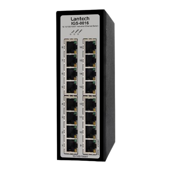
Page 7: Hardware Description
In this paragraph, we will introduce the Industrial switch’s dimensions, port, cabling information, and wiring installation. Front Panel The Front Panel of the IGS-0016/ IES-0016 are shown as below. Front Panel of the Industrial Switch Top View The top panel of the Industrial Switch is equipped one terminal block... -
Page 8: Dimensions
Top panel of the Industrial Switch Converter Dimensions . The dimensions of IGS-0016/IES-0016 are 49 x 152 x 105 mm (W x H x D). The figure below gives the dimensions and views of each side of the 16-port Industrial Ethernet Switch. -
Page 9: Wiring The Power Inputs
Wiring the Power Inputs Please follow the steps below to insert the power wire. 1. Insert the positive and negative wires into the V+ and V- contacts on the terminal block connector. 2. To tighten the wire-clamp screws for preventing the DC wires to loose. Wiring the Fault Alarm Contact The fault alarm contact is in the middle of terminal block connector as the picture shows below. - Page 10 Insert the wires into the fault alarm contact (No. 3 & 4) Note The wire gauge for the terminal block should be in the range between 12~ 24 AWG.
-
Page 11: Led Indicators
1 ~ 16 Green Flashing Networking is active (Upper LED) Not connected to network Connected to network at speed of 1000Mbps (IGS-0016 only) 1 ~ 16 Yellow (Lower LED) Not connected to network or not working at speed of 1000Mbps (IGS-0016 only) -
Page 12: Rj-45 Pin Assignments
RJ-45 Pin Assignments The UTP/STP ports will automatically sense for Fast Ethernet (10Base-T/100Base-TX) or Gigabit Ethernet (10Base-T/100Base-TX/1000Base-T) connection. Auto MDI/MDIX means that the switch can connect to another switch or workstation without changing straight through or crossover cabling. See the figures below for straight through and crossover cable schema. - Page 13 10/100Base-TX Cable Schema Straight Through Cable Schema Crossover Cable Schema 10/100/1000Base-T Pinouts The table below describes the gigabit Ethernet RJ-45 pinouts. Signal name Description BI_DA+ Bi-directional pair A+ BI_DA- Bi-directional pair A- BI_DB+ Bi-directional pair B+ BI_DC+ Bi-directional pair C+ BI_DC- Bi-directional pair C- BI_DB-...
-
Page 14: Cabling
10/100/1000Base-T Cable Schema The following two figures illustrate the 10/100/1000Base-T cable schema. Straight Through Cable Schema Crossover Cable Schema Cabling Use unshielded twisted-pair (UTP) or shielded twisted-pair (STP) cable for RJ-45 connections: 100Ω Category 3, 4 or 5 cable for 10Mbps connections, 100Ω... -
Page 15: Mounting Installation
Mounting Installation DIN-Rail Mounting Assembling the DIN-Rail Clip The DIN-rail clip is screwed on the industrial switch when out of factory. If not, please refer to the following steps and figure to secure the DIN-rail clip on the switch. 1, Use the screws to screw on the DIN-rail clip on the industrial switch. 2, To remove the DIN-rail clip, reverse step 1. - Page 16 Hanging the Industrial Switch Follow the steps below to hang the industrial switch on the DIN rail. 1, First, position the rear side of the switch directly in front of the DIN rail. Make sure the top of the clip hooks over the top of the DIN rail. 2, Push the unit downward.
-
Page 17: Wall-Mount Plate Mounting
Wall-Mount Plate Mounting *Optional Wall Mount Kit required Follow the steps below to mount the industrial switch with the wall mount plates included. 1. To remove the DIN-Rail clip from the industrial switch, unscrew the screws to remove the DIN-Rail clip. 2. - Page 18 Hardware Installation In this paragraph, we will describe how to install the 8-port 10/100/1000Base-TX Industrial Switch and the installation points for the attention.
- Page 19 Installation Steps Unpacked the Industrial switch. Check the DIN-Rail is screwed on the Industrial switch. If the DIN-Rail is not screwed on the Industrial switch. Please refer to DIN-Rail Mounting section for DIN-Rail installation. If you want to wall mount the Industrial switch, then please refer to Wall-Mount Plate Mounting section for wall mount plate installation.
- Page 20 Troubleshooting Verify that you are using the included or appropriate power cord/adapter. Don’t use the power adapter with DC output higher than the power rating of the device. Otherwise, the device will burn down. Select the proper UTP/STP cable to construct your network. Please check that you are using the right cable.
Need help?
Do you have a question about the IGS-0016 and is the answer not in the manual?
Questions and answers