
Related Manuals for DAPAudio GIG-124C


Summary of Contents for DAPAudio GIG-124C
- Page 1 MANUAL ENGLISH GIG-124C Order code: D2284 Highlite International B.V. – Vestastraat 2 – 6468 EX – Kerkrade – the Netherlands...
-
Page 2: Table Of Contents
GIG-124C Table of contents Warning ....................................2 Unpacking Instructions ..............................2 Safety Instructions ................................. 2 Operating Determinations ............................4 Return Procedure ................................4 Claims ....................................4 Description of the device ..............................5 Features ..................................5 Overview ..................................5 Installation ................................... 6 Introduction .................................. -
Page 3: Warning
Save the carton and all packing materials. In the event that a fixture must be returned to the factory, it is important that the fixture be returned in the original factory box and packing. Your shipment includes: GIG-124C mixing console 3-pin IEC power cable ... - Page 4 GIG-124C Never use anything to cover the ground contact. Never leave any cables lying around. Do not insert objects into air vents. Do not connect this system to a dimmer pack. Do not switch the system on and off in short intervals, as this would reduce the system’s life.
-
Page 5: Operating Determinations
GIG-124C Operating Determinations This device is not designed for permanent operation. Consistent operation breaks will ensure that the device will serve you for a long time without defects. The minimum distance between light-output and the illuminated surface must be more than 0.5 meter. -
Page 6: Description Of The Device
GIG-124C Description of the device Features Ultra-low noise discrete MIC Preamps with +48V Phantom Power. 4 MIC Input Channels with XLR and balanced Line Input and Insert I/O and Compressor control. Low Cut for each MIC Input. -
Page 7: Installation
PA installations. The GIG-124C Mixing Console is packed with features that cannot be found in other consoles of its size: 4 mono (provided with ultra-low noise microphone pre-amplifiers and Phantom Power at +48 Volt ) and 4... -
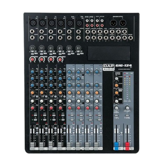
Page 8: Control Elements
GIG-124C Control Elements 1. MIC INPUT JACKS (CHs 1 to 7/8) The balanced XLR input connects to microphones, DI boxes and multicores. 2. LINE INPUT JACKS (CHs 1 to 4) This is a ¼" jack connector which connects to line-level signal sources (for example, keyboards, CD players and wireless microphone receivers). - Page 9 GIG-124C 9. EQUALIZER The high-frequency range is processed with a shelving filter above 12 kHz. You can boost or cut the bands up to 15 dB. When in center position (0 dB), the equalizer has a flat response. The HIGH MID control adjusts the mid frequency range. This is a peak filter which boosts and cuts the frequencies centered at 2,5 kHz.
- Page 10 GIG-124C 17. GR1-2 Each channel is equipped with a GR1-2 switch, which allow you to feed multiple channels to a stereo mixdown. The volume level can be adjusted using the GR1-2 LEVEL fader. 18. MAIN Each channel is equipped with a MAIN switch, pressing this button will send the signal to the MAIN MIX bus.
- Page 11 GIG-124C 28. AUX 1 SEND The Master AUX 1 SEND control adjusts the signals volume level of the respective aux send connector. This way you adjust the sum of the AUX signal on the input channels. 29. ST RETURNS TO AUX This control assigns the ST RETURN signal to their respective AUX SEND outputs.
- Page 12 GIG-124C 41. OPTIONAL MODULES SECTION This section can be selected and installed according to the user's requirements. Open the cover and connect the module to connector CN6. The optional modules are: SMP-R, SMP-S, & Bluetooth-2.1. The signal for module playback can be assigned to Main Mix by 2TK routing.
-
Page 13: Modules
GIG-124C Modules Option One - SMP-S (Order code: D2290) The file system should be FAT16 or FAT32. This player can only decode MP3. It has 7 rank subordinate folders at most. USB port: Allows the connection of any USB memory stick. - Page 14 GIG-124C "Program" mode In Fig. 02, select "Program" to enter into the following interface: "Play list Set ": Set the play list. "Playing List": Play list. Press PRE/ NEXT key to select, press STOP key to return the Fig. 02.
-
Page 15: Option Two - Smp-R (Order Code: D2291)
GIG-124C Option Two - SMP-R (Order code: D2291) The file system of USB memory for USB players is FAT16 and FAT32and these players can only decode MP3. It has 7 rank subordinate folders at most. USB port: Allows the connection of any USB memory stick. -
Page 16: Option Three - Bluetooth Version 2.1 (Order Code: D2292)
GIG-124C Option Three - Bluetooth Version 2.1 (Order code: D2292) Can be paired with mobile phones, tablets or PC Bluetooth adapters to play stereo audio. DISPLAY These two LEDs are used to display different working states: For the first time that the module is powered on, it is in stand-by state and the right LED flashes twice about 2 seconds. -
Page 17: Installation And Connection
Installation and connection At this point you are in a position to successfully operate your GIG-124C Mixing Console. However, we advise you to carefully read the following section to be a real master of your own mixer. Not paying enough attention to the input signal level, to the routing of the signal and the assignment of the signal will result in unwanted distortion, a corrupted signal or no sound at all. -
Page 18: Connection Cables
GIG-124C Connection Cables Take care of your cables, always holding them by the connectors and avoiding knots and twists when coiling them: This gives the advantage of increasing their life and reliability. Periodically check your cables. A great number of problems (faulty contacts, ground hum, discharges, etc.) are caused entirely by using unsuitable or faulty cables. -
Page 19: Block Diagram
GIG-124C Block Diagram Order code: D2284... -
Page 20: Technical Specifications
GIG-124C Technical Specifications MODEL: GIG-124C mixing console Mono channels Microphone input XLR balanced Frequency response 10Hz to 55KHz,+/-3dB Distortion(THD+N) <0.03% at +0dB ,22Hz~22KHz A-weighted Gain range 0dB to 50dB Max. Input +15 dB LOW CUT 100Hz <-100dBr A-weighted Phantom power... - Page 21 GIG-124C Main mix section Max. MAIN MIX output +22dBu XLR balanced (+16dBu un-balanced) AUX range OFF to +15dB Fader range OFF to +10dB PHONES/CONTROL-ROOM range OFF to +15dB <-80dB@20Hz~22KHz A-weighted 1 channel & MAIN level:0dB,the Hum & Noise other :minimum <-80dB@0dB 20Hz~22KHz A-weighted MAIN level:0dB, the other...
-
Page 22: Notes
GIG-124C Notes Order code: D2284... -
Page 23: Dimensions
GIG-124C Dimensions Order code: D2284... - Page 24 ©2013 DAP Audio...
Need help?
Do you have a question about the GIG-124C and is the answer not in the manual?
Questions and answers