
Related Manuals for DAPAudio GIG-202 Tab


Summary of Contents for DAPAudio GIG-202 Tab
- Page 1 MANUAL V1 ENGLISH GIG-202 Tab Ordercode: D2289 Highlite International B.V. – Vestastraat 2 – 6468 EX – Kerkrade – the Netherlands...
-
Page 2: Table Of Contents
GIG-202 Tab Table of contents Warning ....................................2 Unpacking Instructions ..............................2 Safety Instructions ................................. 2 Operating Determinations ............................4 Return Procedure ................................4 Claims ....................................4 Description of the device ..............................5 Features ..................................5 Overview ..................................5 Installation ................................... 6 Introduction .................................. -
Page 3: Warning
Save the carton and all packing materials. In the event that a fixture must be returned to the factory, it is important that the fixture be returned in the original factory box and packing. Your shipment includes: GIG-202 Tab digital mixing console • 19” mounting brackets •... - Page 4 GIG-202 Tab Never leave any cables lying around. • Do not insert objects into air vents. • Do not connect this system to a dimmer pack. • Do not switch the system on and off in short intervals, as this would reduce the system’s life.
-
Page 5: Operating Determinations
You endanger your own safety and the safety of others! The GIG-202 Tab is not intended to be used by persons (including children) with reduced physical and/or mental capabilities or lack of experience and knowledge, unless they have been given supervision or instruction concerning the use of the appliance by a person responsible for their safety. -
Page 6: Description Of The Device
GIG-202 Tab Description of the device Features ● 7” full color LCD touch screen ● Easy to use software interface ● 8 direct access buttons for easy channel control ● Digital Gate/Compressor/4-band full parametric EQ on each input ● 31-band graphical EQ on each output ●... -
Page 7: Installation
Installation Introduction The GIG-202 TAB digital mixing console is the first fully digital mixing console in the GIG range from DAP- Audio. It is a compact digital mixing console that owns all the features of the more advanced digital mixers available on the market. -
Page 8: Control Elements
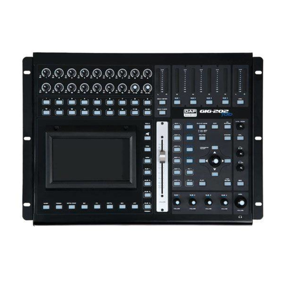
GIG-202 Tab Control Elements Signal / Peak Indicator Green (input detected) / Red color (if the input level is too high, reduce gain) Input Level Control 1-16 Turn the controls 1-16 to set the gain level of the channels’ inputs. - Page 9 GIG-202 Tab Sub1/Aux5 master out control – EQ frequency select Output control Sub1/Aux5 - Sets the EQ frequency value. Sub2/Aux6 master out control – EQ Q-level select Output control Sub2/Aux6 - Sets the EQ Q-level value. Sub3/Aux7 master out control – EQ Gain select Output control Sub 3/Aux7 - Sets the EQ Gain value.
- Page 10 GIG-202 Tab Mixer select button Press this button to see mixer page on the LCD screen, where you can control all the input and output channel levels, solo, mute as well as rename the channel. You can control DCA group level control (see the figure below).
- Page 11 GIG-202 Tab Assign select button Press this button to enter assign page. Signal from a selected input channel can be assigned to Main, AUX1-4, Sub1-4 or AUX5-8 and FX1-2. See the figure below. For detailed information, see page 27. Press once:...
- Page 12 GIG-202 Tab Gate/Comp select button Noise gate attenuates signals which are below the threshold and allows signals to pass through only when they are above a threshold setting. Pressing the button twice will switch to the compressor settings. The compressor reduces the level of an audio signal, if its amplitude exceeds a certain threshold.
- Page 13 GIG-202 Tab EQ select button An equalizer is a filter that allows you to adjust the frequency level in the range of 20Hz-20KHz. See the figure below. For detailed information, see page 35. Press once: Press twice: Ordercode: D2289...
- Page 14 GIG-202 Tab FX select button Press this button to show and edit the settings of internal effects. Each FX owns 12 program effects. See the figure below. For detailed information, see page 37. Press once: Press twice: Ordercode: D2289...
- Page 15 GIG-202 Tab Digital select button Press this button to activate/deactivate the digital channel once you have inserted an optional input/output module. It will light up to indicate that current channel has been selected as digital input or digital output. See the figure below.
- Page 16 GIG-202 Tab LINK select button Input channels, Aux buses and subgroups can be linked as a stereo pair. The button will light up to indicate that the stereo link is active. The stereo pairs are predefined and cannot be changed. They...
- Page 17 GIG-202 Tab Solo/PFL output meter Indicates the output level for a selected channel. If Solo Meter (21) is active, it shows the input Solo/PFL level of the selected channel. Level output indicator Indicates the level output for SUB1-4/Aux 5-8. Main output level indicator Indicates the main level volume output.
- Page 18 GIG-202 Tab DCA 1-6 select buttons Select one of the 6 DCA groups. The channel fader will be activated for the selected DCA group. Main / Sub 1-4 assign buttons Assign outputs to selected channels and FX channels. Subgroups and Auxiliaries can only be routed to main.
- Page 19 GIG-202 Tab Aux 1-4 select buttons Select Aux 1-4. Press these buttons to add DSP settings. FX1/2 select buttons Select FX 1/2. Press these buttons to add DSP settings. Aux send / Aux Out In Aux send mode (button is illuminated), aux 1-4/5-8 (28) can be used to select the corresponding aux on the selected channel.
- Page 20 GIG-202 Tab FX Bypass Press this button to mute the FX return channels. Meters Press this button to get a total overview of all channels. System / Routing Press once to access the system menu. Press again to access the routing menu.
- Page 21 GIG-202 Tab Parameter adjust buttons Navigate through all menus by pressing the up, down, left & right buttons. Encoder This encoder adjusts the parameter values of the selected controls that are shown on the LCD display. Flat EQ button Pressing this button will reset the EQ settings of the selected channel.
- Page 22 GIG-202 Tab Main volume control Controls the main output volume. Solo button Press this button to send the signal of the selected channel(s) to the control room and headphone outputs. Mute button When activated, the selected channel(s) will be muted.
-
Page 23: Rear Panel Connections
GIG-202 Tab Rear panel connections XLR/Jack combo connector 1 - 8 Electronically balanced combo-type input for connecting low impedance microphones. Insert connectors The INS(ert) connector (¼" stereo jack connector) is used for connecting to external signal processors. XLR/Jack combo connector 9 – 16 Electronically balanced combo-type input for connecting low impedance microphones. - Page 24 GIG-202 Tab Power ON / OFF Use the POWER switch to turn on the mixing console. The POWER switch should always be in the “Off” position, when you are about to connect your unit to the mains. AC Inlet with fuse holder Before connecting the unit to the mains, ensure that the voltage setting matches your local voltage.
- Page 25 GIG-202 Tab TRS balanced Main Outputs The MAIN MIX outputs are balanced 1/4" TRS connectors. These outputs are parallel to the XLR Outputs (59). XLR balanced Main Outputs The MAIN MIX outputs are balanced XLR connectors. TRS balanced Inputs 19-20 The 19-20 Line inputs are normally used as effect returns.
-
Page 26: Dsp Control
GIG-202 Tab DSP Control The DSP control is the most important function of the GIG-202 Tab. By using it, you can adjust gate, compressor, EQ, polarity, panning, delay, link, routing, etc. for the selected channels. See the table below for the list of input/output channels and to see which DSP functions are supported. - Page 27 GIG-202 Tab Touch the desired channel. The background will light up. Use the Encoder (36) to adjust the panning. S/Solo and the Solo button (44) will light up simultaneously. “M/Mute” and the Mute button (45) will light up simultaneously. The meter located beside the fader indicates the input signal level.
-
Page 28: Assign Interface
GIG-202 Tab Assign interface Press the Assign button (11) to enter the assign interface. The 20 main inputs, Tape/USB in and internal FX returns can be assigned to any or all of the subgroup outputs, Aux sends and main outputs. - Page 29 GIG-202 Tab Move the fader to adjust the selected channel’s audio input. The fader’s function is the same as that of the Motorized fader (27) on the panel. While adjusting the level, they will both change position synchronously. “Meter“ indicates the signal level activity.
- Page 30 GIG-202 Tab Touch these controls to enter the corresponding page. Press a channel to activate phantom power. Touch “Yes” to activate. Touch this icon to invert the phase of the selected channel's signal (to alter the phase by 180). If the phase reverse is active, the button will light up. The display shows the phase reverse setting in real time.
- Page 31 GIG-202 Tab Aux 1-8 Mode If you switch from Sub1-4 mode to AUX 5-8 mode, you will gain access to more advanced functions. Touch the AUX5-8(SUB1-4) and FX1-2 to assign audio input to these channels or buses. Rotate the Encoder (36) to adjust audio output level. You can also use the Aux 5-8 controls (06-09) on the panel to adjust the volume.
-
Page 32: Channel Interface
GIG-202 Tab Channel interface Touch this icon to invert the phase of the selected channel's signal (to alter the phase by 180). If the phase reverse is active, the button will light up. The display shows the phase reverse setting in real time. The Polarity control can be used for correcting audio signals, which are out of phase, as well as to cancel/reinforce each other. - Page 33 GIG-202 Tab Touch the “OFF” icon to enable the Gate function. Touch the number underneath “Threshold”, then rotate the Encoder (36) or move the long fader on the right-hand side of the LCD display to adjust the Threshold value, which will appear in the central box. While adjusting, the changes will be displayed on the Gate grid.
-
Page 34: Gate Interface
GIG-202 Tab Gate interface Touch this icon to activate/deactivate the Gate for the selected channel. The icon will light up. The display shows the Gate settings in real time. Change the parameters by turning the Threshold, Attack & Release controls and turn the Encoder (36) to set the value. -
Page 35: Compressor Interface
GIG-202 Tab Compressor interface Touch this icon to activate/deactivate the Compressor for the selected channel. It will light up to indicate that the compressor has been enabled. The display shows the compressor setting in real time. Change the parameters by turning the Encoder (36) and set the values of Gain, Threshold, Attack, Release &... -
Page 36: Eq Interface
GIG-202 Tab EQ Interface Touch this icon to activate/deactivate the equalizer for the selected channel. It will light up to indicate that the equalizer has been enabled. The display shows the EQ setting in real time. You can adjust the parameters by sliding the curve on the display or by using the up &... -
Page 37: Routing Interface
GIG-202 Tab Adjust EQ1 to separately set its Frequency, Q and Gain parameters. Touch Type to change the filter to high-pass, low-pass or band-pass filter; the same as EQ2, EQ3 and EQ4. The waveform will be displayed. The rotaries (6-9) on the panel can also be used for setting the frequency, Q-factor, Gain and type of the Low/Low-mid/High-mid/High band. -
Page 38: Fx1-2 Interface
Adjust the effect parameters by rotating the Adjust Parameter control or moving the fader on the right-hand side of the display. Touch this icon to mute current FX effect. The GIG-202 Tab includes 12 kinds of adjustable effects. For the detail operation, see page 47. Ordercode: D2289... - Page 39 GIG-202 Tab List of FX presets Preset Description Parameter Simulate an acoustic space of the Pre Delay; Decay; Room Size; Hi Hall sound Damp; Efx Out; Dry Out Pre Delay; Decay; Room Size; Hi Simulate a studio room with many Room Damp;...
-
Page 40: Dca Set Interface
GIG-202 Tab DCA set interface Press the DCA button (31) located on the panel to enter the page DCA group assignment. The button will flash to indicate that edit mode is active. In order to access this screen, you can also press the DCA icon while operating in the following menus: Mixer, Assign, Channel and System. -
Page 41: Digital In Interface
Note: This feature requires installing the input/output digital card (D2298), being the optional accessory belonging to the GIG-202 Tab. In order to access this page, press the Digital button (15) on the panel or touch the icon on the pages “Assign”... -
Page 42: Digital Out Interface
Note: This feature requires installing the input/output digital card, being the optional accessory belonging to the GIG-202 Tab. In order to access this page, press the Digital button (15) on the panel or touch the icon on pages “Assign” or “System”. Then touch the “Digital Output” button. You can convert digital inputs while operating in all main channels from 1 to 20, AUX1-4, SUB 1-4. -
Page 43: Save Interface
In order to access this page, press the “Save” button on the following pages: Channel, FX1-2 and System. You can save all settings to the internal memory of the GIG-202 Tab. You can save the DSP channels (48 presets), GEQ (48 presets), DFX (104 presets) and Scene (24 presets) which include all adjustments made in the mixer, including the ones mentioned above. -
Page 44: Load Interface
GIG-202 Tab Load interface In order to access this page, press the “Load” button on the following pages: Channel, FX1-2 and System. Now, you can load the presets which you previously saved. You can also load the DSP channels, graphic equalizer GEQ, effects DFX 1-2 or the scenes. -
Page 45: Copy Interface
GIG-202 Tab Copy interface In order to access this page, press the “Copy” button on the following pages: “Assign”, “Channel”, “FX1- 2” and “System”. Select the desired channel or bus which you want to copy settings from, then press the “Copy”... -
Page 46: System Interface
If you touch the Default setting icon, the factory setting will be restored. The GIG-202 Tab is equipped with the safety lock function. Follow the steps below to activate the function. Touch this icon to enter your own password. The system will ask for the previous password. -
Page 47: Geq Interface
In order to access this page, press the GEQ button (42) on the panel or on the “System” page. The GIG-202 Tab mixer has several graphic equalizers: 31 bands 1/3 octave, frequency response 20 Hz - 20 kHz and 24 bit/48 kHz sample rate. This feature is available for: MAIN outputs with stereo equalizer, SUB 1-4 (AUX 5-8) mono and AUX 1-4 mono. - Page 48 GIG-202 Tab Hall The Hall Reverb simulates the reverberation that occurs when sound is recorded in medium to large-sized concert halls. Use the Hall Reverb to give your mix a lush, three-dimensional quality that will make your performance sound larger than life.
- Page 49 GIG-202 Tab Delay This Delay provides the control of the delay (echo) time. The delayed signal is fed back into the Delay line by the Decay rotary, thus creating Delay repeats. Tap the [TAP]Enter (38) button, or touch the Time wheel and turn the Encoder (36) to change the basic Delay time.
- Page 50 GIG-202 Tab Tremolo Stereo Tremolo creates an up and down volume change at a constant and even. The Feedback function adjusts the number of repeats. Depth sets the amount of modulation and Mod Freq adjusts the LFO rate. Efx Out controls the proportion of the processed (Efx) signal sent to the outputs.
- Page 51 GIG-202 Tab Delay Rev Here we have combined Delay and Room reverb, so that a single device can provide a variety of delay settings, plus add just the right type and amount of reverb to the selected signal. The PreDelay rotary controls the amount of time before the reverberation is heard following the source signal.
- Page 52 GIG-202 Tab Flanger Rev Here we have combined Flanger and Room reverb, so that a single device can provide a variety of delay settings, plus add just the right type and amount of reverb to the selected signal. The PreDelay rotary controls the amount of time before the reverberation is heard following the source signal.
-
Page 53: How To
GIG-202 Tab How to: Assign to a DCA group DCA groups are useful in situations where you have a collection of similar signals, and you want to be able to quickly adjust their overall level, but also easily adjust the individual levels of the individual channels assigned to the DCA group. -
Page 54: Change To Mode Aux 1-8 Or Aux 1-4/Bus 1-4
GIG-202 Tab Change to mode AUX 1-8 or AUX 1-4/BUS 1-4 The GIG202-Tab can be used in 2 different modes: 01) 8 auxiliary sends 02) 4 auxiliary sends & 4 busses Switch to 4 AUX / 4 SUB mode: Press the SYSTEM button (34). -
Page 55: Saving And Recalling
GIG-202 Tab Saving and recalling The scenes screen allows setup for saving and recalling different memory scenes of the console (excluding gain settings for the analog mic preamps). Press the SYSTEM button (34). In the Scene part there are 3 options: Load –... - Page 56 GIG-202 Tab Save a scene: Touch the save button. Select an empty preset or an already saved position by touching it. To enter a preset name, touch the preset name. A keyboard screen appears. Enter a name and confirm with Enter.
-
Page 57: Copy Channel Settings
GIG-202 Tab Copy channel settings The settings of one channel can be copied to other channels. Touch the copy button. Select the source channel by touching the Previous and Next Channel buttons. Select the destination channels by touching them. The status of the selected channels changes from OFF to ON. -
Page 58: Pfl A Channel
GIG-202 Tab PFL a channel If Solo is selected on a channel, it is After Fader Listening (AFL). (40), in combination with the solo button (44) to PFL the selected channel(s). Press button (40) is pressed, the master channel will be in PFL mode. -
Page 59: Overall Pre/Post Switching
GIG-202 Tab Overall PRE/POST switching Press the Routing button. Touch the Select button. Touch Aux 1, Aux 2, Aux 3, Aux 4, FX1 or FX2. Touch Enter to confirm your choice. Switch to PRE by touching the PRE button. Switch to POST by touching the POST button. -
Page 60: Installation And Connection
Installation and connection At this point you are in a position to successfully operate your GIG-202 Tab Mixing Console. However, we advise you to carefully read the following section to be a real master of your own mixer. Not paying enough attention to the input signal level, to the routing of the signal and the assignment of the signal will result in unwanted distortion, a corrupted signal or no sound at all. -
Page 61: Connection Cables
GIG-202 Tab Connection Cables Take care of your cables, always holding them by the connectors and avoiding knots and twists when coiling them: This gives the advantage of increasing their life and reliability. Periodically check your cables. A great number of problems (faulty contacts, ground hum, discharges, etc.) are caused entirely by using unsuitable or faulty cables. -
Page 62: Block Diagram
GIG-202 Tab Block Diagram Ordercode: D2289... -
Page 63: Technical Specifications
GIG-202 Tab Technical Specifications Mono channels Mic Inputs: XLR balanced Line Input: TRS balanced Freq Response: 20Hz ~ 20kHz, +/- 1,5dB Distortion (THD-N): <0,01% @ 0dB, 22Hz ~22kHz Max Input Level: +21dBu SNR: < -107dBr Phantom Power: +48V Stereo Channels... - Page 64 ©2016 DAP Audio...
Need help?
Do you have a question about the GIG-202 Tab and is the answer not in the manual?
Questions and answers