Table of Contents
Advertisement
Quick Links
Advertisement
Table of Contents

Subscribe to Our Youtube Channel
Related Manuals for Advantech AIMB-Z51


Summary of Contents for Advantech AIMB-Z51
- Page 1 AIMB-Z51 中国自主化处理器 兆芯KX-6000平台Micro-ATX主板...
- Page 2 Copyright /版权声明 The documentation and the software included with this product are copyrighted 2019 by Advantech Co., Ltd. All rights are reserved. Advantech Co., Ltd. reserves the right to make improvements in the products described in this manual at any time without notice.
- Page 3 Our dealers are well trained and ready to give you the support you need to get the most from your Advantech products. In fact, most problems reported are minor and are able to be easily solved over the phone.
- Page 4 Because of Advantech’s high quality-control standards and rigorous testing, most of our customers never need to use our repair service. If an Advantech product is defective, it will be repaired or replaced at no charge during the warranty period.
- Page 5 销售发票) 。我们对无法提供购买日期证明的产品不提供质量保证服务。 5. 把相关的 RMA 序列号写在外包装上,并将其运送给销售人员。 Initial Inspection/初步检查 Before you begin installing your motherboard, please make sure that the following materials have been shipped: 1 AIMB-Z51 User Manual 1 I/O port bracket 1 CPU Cooler 1 Warranty Card If any of these items are missing or damaged, contact your distributor or sales representative immediately.
- Page 6 在开始安装主板之前,请确保随主板出货的以下材料: 1 AIMB-Z51 用户手册 1 个 I/O 端口支架 1 个 CPU 散热器 1 x 保修卡 如果这些物品丢失或损坏,请立即联系您的经销商或销售代表。装运前,我们仔细检查 了 AIMB-Z51 的机械和电气性能。收到后,应无任何痕迹和划痕,并处于良好的工作状 态。当您打开 AIMB-Z51 的包装时,检查其是否有损坏的迹象。 (例如,箱子损坏、划 痕、凹痕等)如果箱子损坏或不符合规格,请立即通知我们的服务部门或您当地的销售 代表。同时通知承运人。保留装运纸箱和包装材料,供承运人检查。检查后,我们将安 排修理或更换设备。...
-
Page 7: Table Of Contents
目录 Chapter 1 Hardware Configuration/硬件配置..................1 1.1 Introduction/介绍 ..........................2 1.2 Features/特征 ............................2 1.3 Specifications/规格 ..........................3 1.3.1 System/系统 ..........................3 1.3.2 Memory/内存...........................3 1.3.3 Input/Output / 输入/输出 ....................3 1.3.4 Graphics/显示 ........................4 1.3.5 Ethernet LAN/以太局域网 ...................4 1.3.6 Industrial Features/工业特征 ..................4 1.3.7 Mechanical and Environmental Specifications/机械和环境规范 ....5 1.4 Jumpers and Connectors/跳线和连接器... - Page 8 2.5 CPU and System Fan Connector (CPUFAN1, SYSFAN1 ~ SYSFAN2) / CPU 和系统风扇 连接器 ................................. 18 2.6 Front Panel Connector (JFP1) /前面板连接器 ................ 19 2.7Line Out, Mic In Connector (AUDIO1) / Line Out, Mic In 连接器 ........ 20 2.8Case Open Connector (JCASEOP_SW1) / Case Open 连接器 ......... 21 2.9Serial ATA Interface (SATA1 ~ SATA4) / SATA 接口...
- Page 9 Chapter 5 USB3.0 Device Setup/ USB3.0 驱动设置 ................69 5.1 Introduction/介绍 ..........................70 5.2 Windows Driver Setup/ Windows 驱动设置 ................70 Appendix A Programming the Watchdog Timer/看门狗定时器编程 ........71 A.1 Watchdog timer overview/看门狗定时器概述 ..............72 A.2 Programming the Watchdog Timer/看门狗定时器编程............ 72 A.2.1 Example Programs/示例程序...
-
Page 10: Hardware Configuration/硬件配置
Chapter Hardware Configuration 硬件配置... -
Page 11: Introduction/介绍
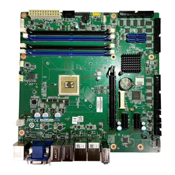
KX-U6780A 2.7GHz/ KX-U6580 2.5GHz/ KX-6640MA 2.2GHz processor and DDR4 2666 memory up to 64 GB. AIMB-Z51 is equipped with one PCIe x16 (Gen3), two PCIe x1 (Gen2) and one Mini PCIe. Triple display interfaces are provided to allow users to connect monitors to the onboard VGA, DVI-D, and HDMI ports at the same time. -
Page 12: Specifications/规格
Supports DDR4 2666 UDIMM up to 64 GB SUSI API: AIMB-Z51 supports SUSI 4.0 API which helps customers to develop their own remote management programs under Windows 10 and Linux. PCIe架构:1个PCIe x16插槽(PCIe x8信号)、2个PCIe x1插槽、1个Mini PCIe插槽 高性能输入/输出能力:通过RJ45的双千兆局域网、4个SATA 3.0、2个USB 3.1、4个... -
Page 13: Graphics/显示
USB port: 2 x USB 3.1, 4 x USB 3.0, 8 x USB 2.0 in LPC: Two LPC connector to support Advantech LPC modules, such as 80 port and GPIO: AIMB-Z51 supports 8-bit GPIO from super I/O for general purpose control application. -
Page 14: Mechanical And Environmental Specifications/机械和环境规范
重量:1kg (2.2 lb) Jumpers and Connectors/跳线和连接器 Connectors on the AIMB-Z51 motherboard link it to external devices such as hard disk drives and a keyboard. In addition, the board has a number of jumpers that are used to configure your system for your application. The tables below list the function of each of the jumpers and connectors. -
Page 15: Board Layout: Jumper And Connector Locations/板卡布局:跳线和连接器位置
JCASEOP_SW1 Caseopen pin header Table 1.2: Connectors/连接器 Label Function COM1 Serial port: RS-232/422/485(pin header) COM2 Serial port: RS-232/422/485(pin header) COM3_6 Serial port: RS-232(pin header),4port COM7_10 Serial port: RS-232(pin header),4port COM11_14 Serial port: RS-232(pin header),4port SYSFAN1 System fan connector (4-pin) SYSFAN2 System fan connector (4-pin) CPUFAN1 CPU fan connector (4-pin) -
Page 16: Block Diagram/框图
USB2H1 TPM1 EATXPWR1 JFP1 COM11-14 GPIO1 SYSFAN1 COM7-11 SYSFAN2 SATA1-4 CPUFAN1 PCIEX16_1 MINIPCIE1 COM3-6 JCASEOP_SW1 COM2 ATX12V2 COM1 LPC1 PCIEX1_1 PCIEX1_2 LAN1_USB3C1 USB3_HDMI1 AUDIO1 USB2_1 USB3_1 LAN2_USB2C1 VGA1+DVI1B Figure 1.1 Jumper and Connector Locations Block Diagram/框图... -
Page 17: Safety Precautions/安全注意事项
Figure 1.2 Block Diagram Safety Precautions/安全注意事项 Warning! Always completely disconnect the power cord from your chassis whenever you work with the hardware. Do not make connections while the power is on. Sensitive electronic components can be damaged by sudden power surges. Only experienced electronics personnel should open the PC chassis. -
Page 18: Jumper Settings/跳线设置
Caution! The computer is provided with a battery-powered Real-time Clock circuit. There is a danger of explosion if battery is incorrectly replaced. Replace only with same or equivalent type recommended by the manufacturer. Discard used batteries according to manufacturer’s instructions. 警告!... -
Page 19: Cmos Clear (Jcmos1) /清除Cmos
1.8.2 CMOS clear (JCMOS1) /清除CMOS The AIMB-Z51 motherboard contains a jumper that can erase CMOS data. Normally this jumper should be set with pins 1-2 closed. If you want to reset the CMOS data, set JCMOS1 to 2-3 closed for just a few seconds, and then move the jumper back to 1-2 closed. -
Page 20: Com1+Com2 Mode Setting By Bios Or Jumper
Table 1.5: Caseopen pin header (JCASEOP_SW1) Function Jumper Setting *Normal 1-2 closed *default setting 1.8.5 COM1+COM2 mode setting by BIOS or jumper (JSETCOM1_V1+ JSETCOM2_V1) /COM1+COM2通过BIOS或跳 线模式设定 Table 1.6: COM1+COM2 mode setting by BIOS or jumper (JCOM1+JCOM2) Function Jumper Setting (1-2,3-4)short,5-6open *RS232(BIOS default ) (1-2,3-4)open,5-6short RS485 with terminal-R... -
Page 21: System Memory/系统内存
System Memory/系统内存 AIMB-Z51 has four 288-pin memory sockets for DDR4 2400/2666 memory modules with maximum capacity of 64 GB (Maximum 16 GB for each DIMM). AIMB-Z51 only supports non-ECC DDR4 memory modules. Please note that AIMB-Z51 does NOT support registered DIMMs (RDIMMs). - Page 22 DIMM module right down into the socket, until you hear a click. This is when the two handles have automatically locked the memory module into the correct position of the DIMM socket. To remove the memory module, just push both handles outward, and the memory module will be ejected by the mechanism in the socket.
-
Page 23: Connecting Peripherals/连接外围设备
Chapter Connecting Peripherals 连接外围设备... -
Page 24: Introduction/介绍
Introduction/介绍 You can access most of the connectors from the top of the board as it is being installed in the chassis. If you have a number of cards installed, you may need to partially remove a card to make all the connections. 当板安装在机箱中时,... -
Page 25: Vga And Dvi Connector (Vga1+Dvi1B) Vga 与 Dvi-D 接口
The AIMB-Z51 is equipped with two high-performance 1000 Mbps Ethernet LANs. They are supported by all major network operating systems. The RJ-45 jacks on the rear plate provide convenient 1000Base-T operation. The AIMB-Z51 provides 16 USB ports. USB2_1, LAN2_USB2C1, USB2H1 and two above of USB3_1 are USB 2.0 ports supporting transmission rate up to 480 Mbps. -
Page 26: Serial Port (Com1 ~ Com14) / 串口
If you are having problems with a serial device, please be sure to check the pin assignments for the connector. AIMB-Z51 提 供 十 四 个 串 口 。 COM1 和 COM2 可 以 通 过 跳 线 设 置 配 置 为 RS- 232/422/485(参见第 1 章),在 BIOS 下为 RS-485 选择正确的设备模式是必要的(参见第... -
Page 27: Cpu And System Fan Connector (Cpufan1, Sysfan1 ~ Sysfan2) / Cpu 和系统风扇
CPU and System Fan Connector (CPUFAN1, SYSFAN1 ~ SYSFAN2) / CPU和系统风扇连接器 SYSFAN2 SYSFAN1 CPUFAN1 If a fan is used, this connector supports cooling fans that draw up to 500 mA (6 W). 如果使用风扇,此连接器支持最高 500 毫安(6 W)的冷却风扇。... -
Page 28: Front Panel Connector (Jfp1) /前面板连接器
Front Panel Connector (JFP1) /前面板连接器 JFP1 There are several external switches and LEDs to monitor and control the AIMB-Z51. You can short-circuit the pin3 and pin4 of JFP1 to turn the motherboard on or off. You can connect a LED to pins 5 and 6 of JFP1 to indicate when the HDD is active. -
Page 29: Line Out, Mic In Connector (Audio1) / Line Out, Mic In 连接器
2.7Line Out, Mic In Connector (AUDIO1) / Line Out, Mic In 连接器 AUDIO1 AUDIO1 Line Out can be connected to external audio devices like speakers or headphones. Mic In can be connected to a microphone. Line Out 可以连接到外部音频设备,如扬声器或耳机。 Mic In 可以连接到麦克风。... -
Page 30: Case Open Connector (Jcaseop_Sw1) / Case Open 连接器
2.8Case Open Connector (JCASEOP_SW1) / Case Open 连接器 JCASEOP_SW1 JCASEOP_SW1 is for chassis with a case open sensor. The buzzer on the motherboard sounds if the case is opened unexpectedly. The default function is disabled and pins 1-2 is bridged by a jumper cap. -
Page 31: Serial Ata Interface (Sata1 ~ Sata4) / Sata 接口
2.9Serial ATA Interface (SATA1 ~ SATA4) / SATA 接口 SATA1 SATA2 SATA3 SATA4 AIMB-Z51 features four high performance serial ATA 3.0 interfaces (up to 600 MB/s) with long, thin, easy-to-run SATA cables. AIMB-Z51 具有四个高性能 SATA 3.0 接口( 最高 600 MB/s ),带有长而细且易于运行的 SATA 线材。... -
Page 32: Pcie X16 Expansion Slot (Pciex16_1) / Pcie X16 扩展槽
2.10PCIe x16 Expansion Slot (PCIEX16_1) / PCIe x16 扩展槽 PCIEX16_1 PCIEX16_1 The AIMB-Z51 provides a PCIe x16 (PCIe x8 signle) slot for users to install an add-on peripheral card for extension requirements. AIMB-Z51 提供了一个 PCIe x16 (PCIe x8 信号) 插槽,供用户安装附加外围卡以满足扩展 需求。... -
Page 33: Pcie X1 Expansion Slot
2.11PCIe x1 Expansion Slot (PCIEX1_1 PCIEX1_2 / PCIe x1 扩展槽 PCIEX1_1 PCIEX1_2 The AIMB-Z51 offers tow PCIe x1 slots for users to install add-on cards for extension requirements. AIMB-Z51 提供两个 PCIe x1 插槽,供用户安装附加卡以满足扩展需求。... -
Page 34: Auxiliary 4-Pin Power Connector (Atx12V2) / 辅助 4-Pin 电源连接器
ATX12V2 To ensure that the enough power is supplied to the CPU, one auxiliary 4-pin power connector is available on the AIMB-Z51. ATX12V2 must be used to provide sufficient 12 V power to ensure the stable operation of the system. -
Page 35: Low Pin Count Connector (Lpc1) / Lpc 连接器
2.13Low Pin Count Connector (LPC1) / LPC连接 器 LPC1 LPC connector on AIMB-Z51 is reserved for Debug AIMB-Z51 上的 LPC 连接器是为 debug 保留的。... -
Page 36: 2.14Trustedplatformmodule (Tpm1) / Tpm连接器
2.14TrustedPlatformModule (TPM1) / TPM连接器 TPM1 TPM Pin Header on AIMB-Z51 is reserved for TPM. AIMB-Z51 上的 TPM 插头是为 TPM 模块保留的。 2.15 GPIO Connector (GPIO1) / GPIO接口 GPIO1... -
Page 37: Mcu Connector (Mcu_Jtag) / Mcu接口
GPIO Pin Header on AIMB-Z51 is reserved for expand GPIO. AIMB-Z51上的GPIO插头是为扩展GPIO保留的。 2.16 MCU Connector (MCU_JTAG) / MCU接口 MCU_JTAG MCU Connector on AIMB-Z51 is reserved for MCU burn.. AIMB-Z51上的MCU连接器是为MCU烧录保留的。... -
Page 38: Micro-Sim Slot (Sim) / Micro-Sim 插槽
Micro-SIM Slot (SIM) / Micro-SIM 插槽 2.17 Micro-SIM slot on AIMB-Z51 is reserved for Micro-SIM expand function,example 4G. AIMB-Z51 上的 Micro-SIM 插槽是为 Micro-SIM 扩展功能保留的,比如 4G。... -
Page 39: Bios Operation/Bios 操作
Chapter BIOS Operation BIOS 操作... -
Page 40: Introduction/介绍
Introduction/介绍 This chapter introduces the basic information of BIOS menu and how to use AIMB-Z51 series BIOS Setup program. With the AMI BIOS Setup program, you can control the specific functions of the computer through the setup BIOS menu. The setup program has multiple menus and submenus. These menu options can be set to control the opening or closing of specific computer functions. -
Page 41: Entering Bios Setup/进入Bios设置
Entering BIOS Setup/进入BIOS设置 Power on the computer, press the < DEL > key on the post interface to enter the AMI BIOS Setup program. In the BIOS main interface, you can enter the submenu through < ENTER > to determine the options. 打开计算机电源,按post界面上的提示信息,按<... - Page 42 Figure 3.3 Main setup screen The Main screen of BIOS program interface is divided into two main frames. The left frame displays all setting options, of which the gray options are not configurable and the blue options can be configured. The right frame will display the description of the corresponding options in the left frame.
-
Page 43: Advanced Bios Features Setup
3.2.2 Advanced BIOS Features Setup Select the Advanced tab from the AIMB-Z51 setup screen to enter the Advanced BIOS setup screen. You can select any of the items in the left frame of the screen, such as CPU configuration, to go to the sub menu for that item. - Page 44 Figure 3.5 TPM Settings Security Device Support Enable/Disable Security Device. NOTE: Your Computer will reboot during restart in order to change State of the Device. 启用/ 禁用BIOS支持安全设备。注意:更改设备状态系统需要重启。 3.2.2.2 ACPI Settings...
- Page 45 Figure 3.6 ACPI Settings Enable ACPI Auto Configuration Enables or Disables BIOS ACPI Auto Configuration. 启用/ 禁用BIOS ACPI自动设置。 Enable Hibernation "Enable or Disable" Hibernation (OS/S4 Sleep State). This option may not be applied in some OS. 启用/ 禁用休眠(OS S4 睡眠状态)。该选项在有些 OS 上不生效。 ...
- Page 46 Figure 3.7 F81216SEC Super IO Configuration Figure 3.8 Serial Port 1 Configuration...
- Page 47 The function like Serial Port 1. 参照串行端口1设置 3.2.2.4 F81216TRD Super IO Configuration Figure 3.13 Second Super IO Configuration AIMB-Z51 supports 2nd super IO F81216TRD COM 1~4. This page of BIOS menu is to set respective serial port configuration. AIMB-Z51支持第二颗 super IO F81216TRD COM 1~4。BIOS菜单的这一页用于设置...
- Page 48 Figure 3.14 Serial Port 1 Configuration Serial Port 1 Configuration – Serial Port "Enable or Disable" Serial Port 1. 开启或关闭串行端口1. Serial Port 2 Configuration Refer to Serial Port 1 Configuration. 参照串行端口1设置 Serial Port 3 Configuration Refer to Serial Port 1 Configuration. 参照串行端口1设置...
- Page 49 Figure 3.13 Third Super IO Configuration AIMB-Z51 supports 3nd super IO NCT6126D COM 1~6. This page of BIOS menu is to set respective serial port configuration. AIMB-Z51支持第二颗 super IO NCT6126D COM 1~6。BIOS菜单的这一页用于设置 NCT6126D的串行端口。...
- Page 50 Figure 3.14 Serial Port 1 Configuration Serial Port 1 Configuration – Serial Port "Enable or Disable" Serial Port 1. 开启或关闭串行端口1. –Mode Selection Selects the serial port mode (RS232/RS422/RS485). The default mode is "RS-232". 选择串行端口模式 (RS232/RS422/RS485)。默认设置为 “RS232”. Serial Port 2 Configuration Refer to Serial Port 1 Configuration.
- Page 51 Serial Port 6 Configuration Refer to Serial Port 3 Configuration. 参照串行端口3设置 3.2.2.6 NCT6126D H/W Monitor This page displays various parameters to monitor system hardware status. Number of fans and VIN voltages are updated dynamically based on hardware. 此页面显示用于监控系统硬件状态的各种参数。风扇数量和VIN电压根据硬件动 态更新。 Figure 3.11 PC Health Status ...
- Page 52 Figure 3.12 Smart Fan Smart Fan Function –Smart SYSFan1 Mode Smart SYSFan 1 Mode Select 智能风扇SYSFan 1模式选择。默认为手动模式。 Manual PWM Setting Fan will work with this Manual PWM Value 当风扇模式选择为手动模式时,该选项显示。手动设置风扇 PWM 值,使风扇按此 PWM 运行。 –Smart CPUFan Mode Smart CPUFan Mode Select 智能风扇CPUFan模式选择。默认为智能风扇模式。...
- Page 53 Fan will work with this Manual PWM Value 当风扇模式选择为手动模式时,此选项显示。手动设置风扇 PWM 值,使风扇按此 PWM 运行。 3.2.2.7 MCU Configuration This page displays the options available in MCU Configuration. 此页面显示MCU Configuration中可用的选项。 3.2.2.8 CPU Configuration This page displays the options available in CPU Configuration. 此页面显示CPU Configuration中可用的选项。...
- Page 54 Figure 3.16 CPU Configuration CPU Threshold low value Control options about temperature threshold. 设置 CPU 温度阈值低值 CPU Threshold high value Control options about temperature threshold. 设置 CPU 温度阈值高值 AVX Supported AVX Supported. 开启或关闭 AVX 支持。 TSC deadline mode ...
- Page 55 Figure 3.17 USB Configuration Legacy USB Support This is for supporting USB device under legacy OS such as DOS. When choosing "AUTO", the system will automatically detect if any USB device is plugged into the computer . Enable USB legacy mode when a USB device is plugged, and disable USB legacy mode when no USB device is plugged.
- Page 56 Port 60/64 Emulation Enables I/O port 60h/64h emulation support. This should be enabled for the complete USB keyboard legacy support for non-USB aware OSes. 启用/ 禁用 I/O 端口 60h/64h 模拟支持。对于不能识别 USB 的操作系统,应启 用此项,以获得完整的USB 键盘传统支持。 USB transfer time-out Allows you to select the USB transfer time-out value. [1,5,10,20sec] 为控制、批量和中断传输设置超时值。...
- Page 57 Figure 3.18 CSM Configuration CSM Support "Enable or Disable" CSM Support. 启用或禁用 CSM 支持。默认设置为[Enabled]。 GateA20 Active GateA20 (GA20) can be disabled using BIOS Services. Do not allow disabling GA20; This option is useful when any RT code is executed above 1MB. [Upon Request]:用户可通过...
- Page 58 Legacy Only: Allows Legacy boot device only. UEFI and Legacy: Allows both UEFI and Legacy. 过滤启动设备类型 UEFI Only: 只允许UEFI启动设备 Legacy Only: 只允许传统启动设备 UEFI and Legacy: 允许UEFI和传统启动设备. Network Select execution mode of Network. 此项用于选择UEFI 和传统PXE OpROM 的执行模式。 Storage Select execution mode of Storage. 此项用于选择UEFI 和传统存储...
- Page 59 Figure 3.20 Network Stack enable Network Stack "Enable or Disable" UEFI Network Stack. Default is ‘Disabled’. 启用/ 禁用 UEFI 网络堆栈。默认设置为[Disabled]。 – Ipv4 PXE Support Enable/Disable IPv4 PXE boot support. This option is only available when Network Stack is enabled. 启用/ 禁用...
-
Page 60: Chipset
设置按下 ESC 键以中断 PXE 启动的等待时间。 – Media detect count Number of times the presence of media will be checked. 设置检查媒体的次数。 3.2.3 Chipset Figure 3.21 Chipset This page provides information of the chipset on AIMB-Z51. 本页提供AIMB-Z51 chipset 的信息。 3.2.3.1 North Bridge... - Page 61 Figure 3.22 North Bridge DRAM Configuration Display memory information 显示内存信息...
- Page 62 Figure 3.23 DRAM Configuration Video Configuration Figure 3.24 Video Configuration VGA Share Memory ...
- Page 63 This option determines how much memory is allocated to the graphics card. Users can choose between 64MB, 128MB, 256MB, 512MB and 1024MB, or select the automatic mode, and the system will automatically allocate enough memory to the graphics card. 选择显存大小。可以选择64MB, 128MB, 256MB, 512MB and 1024MB,或者选择 自动模式,系统会自动给显卡分配足够显存。...
- Page 64 Figure 3.26 RAIDA Host Control 3.2.3.2 South Bridge...
- Page 65 Figure 3.26 South Bridge User can configure south bridge parameter. 用户可以设定南桥配置 3.2.3.2.1 USB Configuration Figure 3.27 South USB configuration Usb S4 WakeUp Control Usb S4 Wake Up Enable/Disable selection 启用/ 禁用 USB S4 唤醒功能 Usb OC Enable/Disable Usb OC Enable/Disable selection 启用/ 禁用...
- Page 66 Figure 3.28 PMU_ACPI configuration 3.2.3.2.3 HDAC Configuration...
- Page 67 Figure 3.29 HDAC configuration 3.2.3.2.4 SNMI Configuration Figure 3.30 SNMI configuration 3.2.3.2.5 Other Configuration...
- Page 68 Figure 3.31 Other configuration 3.2.3.3 IOE Setup...
- Page 69 Figure 3.32 IOE Setup User can configure IOE parameter. 用户可以设定 IOE 配置 3.2.3.3.1 IOE SATA Drive Setup Figure 3.33 IOE SATA Drive Setup CND003 SATA Controller Select whether to enable or disable SATA controller. 启用/ 禁用 SATA 控制器 Configure SATA as Select IDE/AHCI Mode.
-
Page 70: Security
Figure 3.34 IOE USB Drive Setup USB S4 WakeUp Enable or Disable USB S4 Wake Up. 启用/ 禁用 USB S4 唤醒功能 IOE USB OC Enable Enable or Disable IOE USB OC function. 启用/ 禁用 IOE USB 过流保护功能 3.2.4 Security... -
Page 71: Boot
Figure 3.35 Security Select Security Setup from the AIMB-Z51 Setup main BIOS setup menu. All Security Setup options, such as password protection is described in this section. To access the sub menu for the following items, select the item and press <Enter>. -
Page 72: Save & Exit
Figure 3.36 Boot Setup Prompt Timeout Directly key in the number, or use the <+> and <-> keys to adjust the number of seconds to wait for setup activation key. 此项允许用户设置提示进入setup界面等待的秒数。默认设置为 [1]。使用<+> 或 <-> 键可以增加或减少秒数。 Bootup NumLock State Default state for the NumLock key during power on. - Page 73 Figure 3.37 Save & Exit Save Changes and Exit When you complete system configuration, select this option to save your changes, exit BIOS setup and reboot the computer so the new system configuration parameters can take effect. Select Exit Saving Changes from the Exit menu and press <Enter>. The following message appears: Save Configuration Changes and Exit Now? [Yes] [No]...
- Page 74 message appears: Quit without saving? [Yes] [No] Select Yes to discard changes and exit. 选择此项将退出设置且不保存对系统配置的任何修改。 1.请从退出菜单中选择“Discard Changes and Exit” 并按下 <Enter> 键。屏 幕上将出现以下信息: Discard Changes and Exit Setup Now? [Yes] [No] 2.选择 Yes 将放弃修改并退出设置。 Save Changes and Reset When you have completed the system configuration changes, select this option to save the changes and reboot the system, so the new system configuration parameters can take effect.
-
Page 75: Chapter 4 C-960 Graphic Device Setup/ C-960 Graphic 驱动设置
Chapter C-960 Graphic Device Setup C-960 Graphic 驱动设置... -
Page 76: Before You Begin//安装前
Before you begin//安装前 To facilitate the installation of the enhanced display drivers and utility software, read the instructions in this chapter carefully. The drivers for the AIMB-Z51 are located on Advantech support website (http://www.advantech.com/support).. Before you begin, it is important to note that most display drivers need to have the relevant software application already installed in the system prior to installing the enhanced display drivers. -
Page 77: Windows Driver Setup/ Windows 驱动设置
能显示选项和32位3D图形引擎。三重独立显示、用于扩展和克隆多显示模式 的宽屏平板的增强显示模式以及优化的3D支持提供了密集而逼真的视觉体 验。 Windows Driver Setup/ Windows驱动设置 Enter the Advantech support website, then search product AIMB-Z51. You can see "Graphics" driver inside 进入研华科技网站,然后搜索产品AIMB-Z51。你可以在里面看到“Graphics”驱动程 序。... - Page 78 Chapter USB3.0 Device Setup USB3.0 驱动设置...
- Page 79 Introduction/介绍 Win7 32&64bit need install USB3.0 Driver. Win 7 32 & 64位需要安装USB3.0驱动程序。 Windows Driver Setup/ Windows驱动设置 Enter the Advantech support website, then search product AIMB-Z51. You can see "USB3.0" driver inside. 进入研华科技网站,然后搜索产品AIMB-Z51。里面可以看到“USB3.0”驱动。...
- Page 80 Appendix Programming the Watchdog Timer 看门狗定时器编程...
- Page 81 The AIMB-Z51’s watchdog timer can be used to monitor system software operations and take corrective action if the software fails to function within the programmed period. This section describes the operation of the watchdog timer and how to program it.
- Page 82 Unlock NCT6106D Select register of watchdog timer Enable the function of the watchdog timer Use the function of the watchdog timer lock NCT6106D...
- Page 83 Table A.1: Watchdog timer registers Address of Read/ Value (2F) & description register (2E) Write Write this address to I/O address port 2E (hex) twice to 87 (hex) unlock the NCT6126D. 07 (hex) write Write 08 (hex) to select register of watchdog timer. Write 01 (hex) to enable the function of the watchdog timer.
- Page 84 ;----------------------------------------------------------- Dec dx; Enable the function of watchdog timer Mov al,30h Out dx,al Inc dx Mov al,01h Out dx,al ;----------------------------------------------------------- Dec dx ; Set second as counting unit Mov al,0f0h Out dx,al Inc dx In al,dx And al,not 08h Out dx,al ;----------------------------------------------------------- Dec dx ;...
- Page 85 Out dx,al ;----------------------------------------------------------- Dec dx ; Set minute as counting unit Mov al,0f0h Out dx, al Inc dx In al,dx Or al, 08h Out dx,al ;----------------------------------------------------------- Dec dx ; Set timeout interval as 5 minutes and start counting Mov al,0f1h Out dx,al Inc dx Mov al,5;...
- Page 86 Inc dx In al,dx Or al,80h Out dx,al ;----------------------------------------------------------- Dec dx ; lock NCT6126D Mov al,0aah Out dx,al Enable watchdog timer to be reset by keyboard ;----------------------------------------------------------- Mov dx,2eh ; unlock NCT6126D Mov al,88h Out dx,al Out dx,al ;----------------------------------------------------------- Mov al,07h ; Select registers of watchdog timer Out dx,al Inc dx Mov al,08h...
- Page 87 Out dx,al ;----------------------------------------------------------- Mov al,07h ; Select registers of watchdog timer Out dx,al Inc dx Mov al,08h Out dx,al ;----------------------------------------------------------- Dec dx ; Enable the function of watchdog timer Mov al,30h Out dx,al Inc dx In al,dx Or al,01h Out dx,al ;----------------------------------------------------------- Dec dx ;...
- Page 88 Appendix I/O Pin Assignments I/O Pin 分配...
- Page 89 HDMI Port and USB 3.1 Port (USB3_HDMI1) Table B.1: HDMI Port and USB 3.1 Port (USB3_HDMI1) Signal Signal TMDS_DATA2+ TMDS_DATA2- TMDS_DATA1+ TMDS_DATA1- TMDS_DATA0+ TMDS_DATA0- TMDS_CLOCK+ TMDS_CLOCK- HOT_PLUG_DETECT D-_1 D+_1 STDA_SSRX-_1 STDA_SSRX+_1 STDA_SSTX-_1 STDA_SSTX+_1 D-_2 D+_2 STDA_SSRX-_2 STDA_SSRX+_2 STDA_SSTX-_2 STDA_SSTX+_2 GND_F GND_F GND_F GND_F...
- Page 90 LAN Port and USB 3.1 Port (LAN1_USB3C1) Table B.2.1: LAN Port and USB 3.1 Port (LAN1_USB3C1) Signal Signal LAN1_ACTLED# LAN1_MDI2+ LAN1_a_ACT LAN1_MDI2- LAN1_EEDO_LINK1000# LAN1_MDI3+ LAN1_EESK_LINK100# LAN1_MDI3- LAN1_COMG LAN1_GND LAN1_MDI0+ LAN1_MDI0- LAN1_MDI1+ LAN1_MDI1- Table B.2.2: USB 3.1 Port (LAN1_USB3C1C) Signal STDA_SSRX- STDA_SSRX+ Shield GND_DRAIN STDA_SSTX-...
- Page 91 LAN Port and USB 2.0 Port (LAN1_USB2C1) Table B.3.1: LAN Port and USB 3.1 Port (LAN2_USB2C1A) Signal Signal LAN2_ACTLED# LAN2_MDI2+ LAN2_a_ACT LAN2_MDI2- LAN2_EEDO_LINK1000# LAN2_MDI3+ LAN2_EESK_LINK100# LAN2_MDI3- LAN2_COMG LAN2_GND LAN2_MDI0+ LAN2_MDI0- LAN2_MDI1+ LAN2_MDI1- Table B.3.2: USB 2.0 Port (LAN1_USB3C1C) Signal GND_F GND_F USB 2.0 Port (USB2_1) Table B.4: USB 2.0 TypeA (USB2_1)
- Page 92 USB-2_B USB+2_B GND_3 USB-1_B USB+1_B GND_2 USB-0_B USB+0_B GND_1 GND_F GND_F GND_F GND_F GND_F GND_F USB 2.0&3.1 Port (USB3_1) Table B.5: USB 2.0&3.1 Port (USB3_1) Signal Signal D-_4 D+_4 STDA_SSRX-_4 STDA_SSRX+_4 STDA_SSTX-_4 STDA_SSTX+_4 D-_3 D+_3 STDA_SSRX-_3 STDA_SSRX+_3 STDA_SSTX-_3 STDA_SSTX+_3 D-_2 D+_2 D-_1 D+_1...
- Page 93 USB 2.0 Header (USB2H1) Table B.6: USB 2.0 Header (USB2H1) Signal Signal USB2_PCH_USB2H2- USB2_PCH_USB2H1- USB2_PCH_USB2H2+ USB2_PCH_USB2H1+ VGA Connector (VGA1+DVI1B) Table B.7.1: VGA Connector (VGA1+DVI1B) Signal Signal VGA1_b_R VCC_VGA VGA1_b_G GND_VGA VGA1_b_B VGA1_a_DDAT GND_VGA VGA1_b_HS VGA1_FOC_ON VGA1_b_VS GND_VGA VGA1_a_DCLK GND_VGA Table B.7.2: DVI-D Connector (VGA1+DVI1B) Signal Signal TMDS0_D2-_C...
- Page 94 TMDS0_DDC_SCL TMDS0_D0+_C TMDS0_DDC_SDA TMDS0_D1-_C TMDS0_D1+_C TMDS0_CLK+_C TMDS0_CLK-_C RS-232/422/485 & RS-232 BOX HEADER (COM1~ COM2) Table B.8.1: RS-232/422/485 DB-9 Connector (COM1) Signal Signal COM1_DCD_422TX- COM1_DSR# COM1_RXD_422TX+ COM1_RTS# COM1_TXD_422RX+ COM1_CTS# COM1_DTR_422RX- COM1_RI_V# Table B.8.2: RS-232/422/485 DB-9 Connector (COM2) Signal Signal COM2_DCD_422TX- COM2_DSR# COM2_RXD_422TX+ COM2_RTS# COM2_TXD_422RX+...
- Page 95 RS-232 BOX HEADER connector (COM3~ COM14) Table B.9.1: RS-232 BOX HEADER connector (COM3-6) Signal Signal COM3_DCD# COM3_DSR# COM3_SIN COM3_RTS# COM3_SOUT COM3_CTS# COM3_DTR# COM3_RI# COM4_DCD# COM4_DSR# COM4_SIN COM4_RTS# COM4_SOUT COM4_CTS# COM4_DTR# COM4_RI# COM5_DCD# COM5_DSR# COM5_SIN COM5_RTS# COM5_SOUT COM5_CTS# COM5_DTR# COM5_RI# COM6_DCD# COM6_DSR# COM6_SIN COM6_RTS#...
- Page 96 COM8_DTR# COM8_RI# COM9_DCD# COM9_DSR# COM9_SIN COM9_RTS# COM9_SOUT COM9_CTS# COM9_DTR# COM9_RI# COM10_DCD# COM10_DSR# COM10_SIN COM10_RTS# COM10_SOUT COM10_CTS# COM10_DTR# COM10_RI# Table B.9.3: RS-232 BOX HEADER connector (COM11-14) Signal Signal COM11_DCD# COM11_DSR# COM11_SIN COM11_RTS# COM11_SOUT COM11_CTS# COM11_DTR# COM11_RI# COM12_DCD# COM12_DSR# COM12_SIN COM12_RTS# COM12_SOUT COM12_CTS# COM12_DTR# COM12_RI#...
- Page 97 B.10 CPU and System Fan Power Connector (CPUFAN1, SYSFAN1 ~ SYSFAN2) Table B.10: CPU and System Fan Power Connector (CPUFAN1, SYSFAN1 ~ SYSFAN2) Signal +12 V Detect PWMOUT B. 11 5*2-pin wafer for Front panel of LED & Power button & System reset button (JFP1) Table B.11: 5*2-pin wafer for Front panel of LED &...
- Page 98 A_z_MIC2-R AUD_FP_PRESENCE# A_z_LINE2-R A_MIC2-JD A_FIO_SENSE A_z_LINE2-L A_LINE2-JD B.13 PCIE X1 Connector (PCIEX1_1) Table B.13: PCIE X1 Connector (PCIEX1_1) Signal Signal +V12 +V12 +V12 +V12 +V12 SMBCK PCIE1_JTAG2 SMBDT PCIE1_JTAG3 +V3.3 PCIE1_JTAG5 PCIE1__JTAG1 +V3.3 +V3.3SB +V3.3 PCIE_WAKE# PCIEX1_1_RST# I_PCIECLK1+ I_PEX_PHYA_TX1+_C I_PCIECLK1- I_PEX_PHYA_TX1-_C I_PEX_PHYA_RX1+ -PE2PRT2...
- Page 99 B.14 PCIE X1 Connector (PCIEX1_2) Table B.14: PCIE X1 Connector (PCIEX1_2) Signal Signal +V12 +V12 +V12 +V12 +V12 SMBCK PCIE2_JTAG2 SMBDT PCIE2_JTAG3 +V3.3 PCIE2_JTAG5 PCIE2__JTAG1 +V3.3 +V3.3SB +V3.3 PCIE_WAKE# PCIEX1_2_RST# I_PCIECLK2+ I_PEX_PHYA_TX2+_C I_PCIECLK2- I_PEX_PHYA_TX2-_C I_PEX_PHYA_RX2+ PCIEX1_2_PRSNT# I_PEX_PHYA_RX2- B.15 PCIE X16 Connector (PCIEX16_1)
- Page 100 Table B.15: PCIE X16 Connector (PCIEX16_1) Signal Signal +V12 PCIE1_PRSNT1# +V12 +V12 +V12 +V12 SMBCK +V3.3 SMBDT +V3.3 +V3.3 +V3.3 +V3.3 +V3.3SB +V3.3 PCIE_WAKE# PCIEX16_RST# PCIECLK3P PEG_CPU_PCIE1_a_TX0+ PCIECLK3N PEG_CPU_PCIE1_a_TX0- PEX_PHYA_RX2+ PCIE1_PRSNT2#_R PEX_PHYA_RX2- PEG_CPU_PCIE1_a_TX1+ PEG_CPU_PCIE1_a_TX1- PEX_PHYA_RX3+ PEX_PHYA_RX3- PEG_CPU_PCIE1_a_TX2+ PEG_CPU_PCIE1_a_TX2- PEX_PHYA_RX4+ PEX_PHYA_RX4- PEG_CPU_PCIE1_a_TX3+ PEG_CPU_PCIE1_a_TX3- PEX_PHYA_RX5+...
- Page 101 PEG_CPU_PCIE1_a_TX6- PEX_PHYA_RX8+ PEX_PHYA_RX8- PEG_CPU_PCIE1_a_TX7+ PEG_CPU_PCIE1_a_TX7- PEX_PHYA_RX9+ PCIE1_PRSNT2#_R PEX_PHYA_RX9- PCIE1_PRSNT2#_R...
- Page 102 B.16 Case Open Connector (JCASEOP_SW1) Table B.16: Case Open Connector (JCASEOP_SW1) Signal SIO_CASEOP B.17 Low Pin Count Connector (LPC1) Table B.17: Low Pin Count Connector (LPC1) Signal Signal CK33M_LPC LPCAD1 PRST_SIO1# LPCAD0 -LPCFRAME +V3.3 LPCAD3 LPCAD2 B.18 GPIO Connector (GPIO1) Table B.18: GPIO Connector (GPIO1) Signal Signal...
- Page 103 B.19 MCU Connector (MCU_JTAG) Table B.19: MCU Connector (MCU_JTAG) Signal SWCLK SWDIO MCU_NRST# MCU_UART_TX MCU_UART_RX B.20 MINIPCIE X1 connector (MINIPCIE1) Table B.20: MINIPCIE X1 Connector (MINIPCIE1) Signal Signal PCIE_WAKE# +V3.3A_MPCIE +V1.5 I_PCIECLK0- I_PCIECLK0+ MPCIE_H_DIS# PLTRST_MPCIE# I_PEX_PHYA_RX0- +V3.3A_MPCIE I_PEX_PHYA_RX0+ +V1.5...
- Page 104 SMBCK I_PEX_PHYA_TX0- SMBDT I_PEX_PHYA_TX0+ USBHP7_Z_P- USBHP7_Z_P+ +V3.3A_MPCIE +V3.3A_MPCIE +V1.5 +V3.3A_MPCIE B.21 Front Panel Audio Connector (FPAUD1) Table B.21: Front Panel Audio Connector (FPAUD1) Signal Signal MIC2-L_R GND_A MIC2-R_R AUD_FP_PRESENCE# LINE2-R_R MIC2-JD FRONT-IO-SENSE LINE2-L_R LINE2-JD B.22 ATX/AT Connector (PSON1) Table B.22: ATX/AT Connector (PSON1) Signal VCCAT +V3.3SB...
- Page 105 B.23 CMOS Connector (JCMOS1) Table B.23: CMOS Connector (JCMOS1) Signal VBAT RTCRST# B.24 COM1 & COM2 mode select (JSETCOM1_V1 & JSETCOM2_V1) Table B.24.1: COM1 & COM2 mode select (JSETCOM1_V1 ) Signal Signal COM1_RI# COM1_RI_VA# COM1_RI_VA# +V12 COM1_RI_VA# Table B.24.2: COM1 & COM2 mode select (JSETCOM2_V1) Signal Signal COM2_RI#...
- Page 106 +3.3VATX +3.3VATX +3.3VATX -V12 SPS_PS_ON#_R PG_a_ATX +V5SB +V12 +V12 +3.3VATX B.26 ATX 12V auxiliary power connector for CPU (ATX12V1) Table B.26: ATX 12V auxiliary power connector for CPU (ATX12V1) Signal Signal +V12_4P +V12_4P B.27 Serial ATA (SATA1/ SATA2/ SATA3/ SATA4) Table B.27: Serial ATA (SATA1/ SATA2/ SATA3/ SATA4) Signal I_PEXPHYB_TX+...
- Page 107 I_PEXPHYB_RX+ B.28 PIN header connector (TPM1) Table B.28: TPM PIN header connector (TPM1) Signal Signal TPM_CLK TPM_FRAME TPM_RST# TPM_SMB_DAT TPM_AD3 TPM_AD1 +V3.3 TPM_AD2 TPM_AD0 +V3.3SB TPM_SERIRQ TPM_PD# TPM_SMB_CLK Micro-SIM Slot (SIM) / Micro-SIM 插槽 B.29 Table B29: Micro-SIM Slot (SIM) / Micro-SIM 插槽 Signal SIM_PWR M_SIM_RST#...
- Page 108 No part of this publication may be reproduced in any form or by any means, electronic, photocopying, recording or otherwise, without prior written permission of the publisher. All brand and product names are trademarks or registered trademarks of their respective companies. © Advantech Co., Ltd. 2021...
Need help?
Do you have a question about the AIMB-Z51 and is the answer not in the manual?
Questions and answers