
Related Manuals for Advantech AIMB-788


Summary of Contents for Advantech AIMB-788
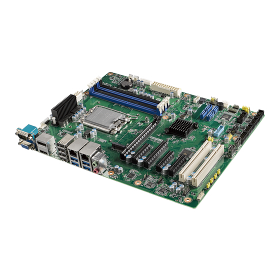
- Page 1 User Manual AIMB-788 ® LGA1700 Intel Core™ i9/i7/i5/i3 ATX Motherboard with DP/HDMI/ VGA, DDR4, USB 3.2, M.2...
- Page 2 No part of this manual may be reproduced, copied, translated or transmitted in any form or by any means without the prior written permission of Advantech Co., Ltd. Information provided in this manual is intended to be accurate and reliable. How- ever, Advantech Co., Ltd.
- Page 3 Caution! There is a danger of a new battery exploding if it is incorrectly installed. Do not attempt to recharge, force open, or heat the battery. Replace the battery only with the same or equivalent type recommended by the man- ufacturer. Discard used batteries according to the manufacturer's instructions. AIMB-788 User Manual...
- Page 4 It should be free of marks and scratches and in perfect working order upon receipt. As you unpack the AIMB-788, check it for signs of ship- ping damage. (For example, damaged box, scratches, dents, etc.) If it is damaged or it fails to meet the specifications, notify our service department or your local sales representative immediately.
-
Page 5: Table Of Contents
1.8.11 PCIe SMBus connection setting of clock (SMB3) and data (SMB4) for PCIE1 slot................13 Table 1.12:PCIe SMBus connection setting of clock (SMB3) and data (SMB4) for PCIE1 slot13 Memory Installation Procedures.............. 14 1.10 Processor Installation................14 Chapter Connecting Peripherals ....15 Introduction ..................... 16 AIMB-788 User Manual... - Page 6 GPIO Connector (GPIO1) ............... 26 2.19 SMBus Connector (SMBUS1)..............26 2.20 Serial Peripheral Interface (SPI) Connector (SPI_TPM1)....... 27 Table 2.3: Advantech SPI TPM Module List......27 Chapter BIOS Operation ......... 29 Introduction ..................... 30 Figure 3.1 Main setup screen ........... 30 Entering BIOS Setup................
- Page 7 Introduction ..................... 76 Windows Driver Setup................76 Chapter Integrated Graphic Device Setup ..77 Introduction ..................... 78 Windows Driver Setup................78 Chapter Intel® ME ..........79 Introduction ..................... 80 Installation ....................80 Chapter Configuration......81 Introduction ..................... 82 Features ....................82 AIMB-788 User Manual...
- Page 8 Table B.16:SMBus Connector (JFP2) ........98 B.14 ATX Soft Power Switch (JFP1) ............... 98 Table B.17:ATX Soft Power Switch (JFP1) ........ 98 B.15 Reset Connector (JFP1) ................. 98 Table B.18:Reset Connector (JFP1)........... 98 B.16 8-pin Alarm Board Connector (VOLT1)........... 98 AIMB-788 User Manual viii...
- Page 9 Table B.24:Front Panel Audio Connector (FPAUD1)....100 B.22 Serial Peripheral Interface (SPI) Connector (SPI_TPM1) ..... 101 Table B.25:Serial Peripheral Interface(SPI) Connector (SPI_T- PM1)101 B.23 Watchdog Timer Output and HW Monitor Alarm (JWDT1+JOBS1)..101 Table B.26:Watchdog Timer Output and HW Monitor Alarm (JWDT1+JOBS1)101 AIMB-788 User Manual...
- Page 10 AIMB-788 User Manual...
-
Page 11: Chapter 1 Hardware Configuration
Chapter Hardware Configuration... -
Page 12: Introduction
GB. AIMB-788 delivers cost-effective integrated graphics with 1 GB max shared memory when 2 GB or more system memory is installed. AIMB-788 is equipped with one PCIe x16, one PCIe x8, three PCIe x4, and two PCI slots. It’s triple display interfaces allow users to simultaneously connect monitors to the on-board DP, HDMI, and VGA ports. -
Page 13: Specifications
Legacy platforms are not supported. 1.3.2 Memory RAM: Up to 128 GB in four 288-pin DIMM sockets supporting dual-channel DDR4 3200 SDRAM. AIMB-788 supports non-ECC unbuffered DIMMs and does not support any memory configuration that mixes non-ECC with ECC unbuffered DIMMs. 1.3.3 Input/Output PCIe slot: 1 x PCIe x16 Gen 4, 1 x PCIe x8 (x4 Gen 3 link), 3 x PCIe x4 Gen 3 ... -
Page 14: Ethernet Lan
Board size: 304.8 x 244 mm (12 x 9.6 in) Weight of board: 0.7 kg (1.54 lb) Note! All specifications are subject to the data-sheet on the official website. The information in this manual is subject to change without notice. AIMB-788 User Manual... -
Page 15: Jumpers And Connectors
Jumpers and Connectors Connectors on the AIMB-788 motherboard link it to external devices such as hard disk drives and a keyboard. In addition, the board has a number of jumpers that are used to configure your system for your application. -
Page 16: Board Layout: Jumper And Connector Locations
Intel LGA1700 PCI2 Core i9/i7/i5/i3 CPU PCI1 JPCICLK1 NVME1 SMB4 SMB3 SMB2 SYSFAN3 SMB1 PCIE2, PCIE3, PCIE4, PCIE5 PCIE1 JFV1 COM1 LANLED1 VGA1 SPDIF_OUT1 FPAUD1 USB2C1 LAN2 LAN1 AUDIO1+AUDIO2 USB3C2 HDMI1 USB3C1 Figure 1.1 Jumper and Connector Locations AIMB-788 User Manual... -
Page 17: Block Diagram
AUDIO1+AUDIO2 USB3C1 VGA1 HDMI1 USB2C1 USB3C2 Figure 1.2 I/O Connectors Note! AIMB-788 is not compatible with 1U chassis due to the height of the rear USB 2.0 ports. Block Diagram DDR4 3200 Channel A DDR4 3200 HDMI Level Shifter HDMI... -
Page 18: Safety Precautions
1, 2, and 3. In this case you connect either pins 1 and 2, or 2 and 3. A pair of needle-nose pliers may be useful when set- ting jumpers. AIMB-788 User Manual... -
Page 19: Cmos Clear (Jcmos1) And Intel® Me Update (Jme1)
1.8.3 Watchdog timer output and OBS alarm (JWDT1+JOBS1) The AIMB-788 contains a watchdog timer that will reset the CPU. This feature means the AIMB-788 will recover from a software failure or an EMI problem. The JWDT1 jumper settings control the outcome of what the computer will do in the event the watchdog timer is tripped. -
Page 20: Atx/At Mode Selection (Pson1)
USB power source switch between +5V and +5V_DUAL for onboard USB ports (JUSB_2) The AIMB-788 allows users to set USB power between +5 V_DUAL and +5 V. When the jumper is set as +5 V, the board doesn't support wake up from S3 via keyboard or mouse Table 1.6: USB power source switch for onboard USB ports... -
Page 21: Pci Clock Selection (Jpciclk1)
Use JSETCOM3 to select the RS-232/422/485 mode for COM3. Refer to Chapter 3 for further selection of device mode in the BIOS menu. The default setting is RS-232. Table 1.8: COM3 RS-232/422/485 jumper setting (JSETCOM3) Function Setting *RS-232 RS-422 RS-485 *default setting AIMB-788 User Manual... -
Page 22: Com3 Rs-422/485 Termination Resistor (Jt1, Jr1)
If JFV1 is set to enable, a dummy monitor on the VGA port is created to prevent the on-board graphics from being switched off while no physical monitors are connected. This function is useful when you control the AIMB-788 via remote KVM (such as Intel® AMT) and do not intend to connect any monitors. -
Page 23: Pcie Smbus Connection Setting Of Clock (Smb1) And Data (Smb2) For Pcie2 ~ Pcie5 Slots
1-2 closed or pins 2-3 closed. Table 1.12: PCIe SMBus connection setting of clock (SMB3) and data (SMB4) for PCIE1 slot Function Jumper Setting *Enable PCIe SMBus connec- 1-2 closed tion Disable PCIe SMBus connec- 2-3 closed tion * default setting AIMB-788 User Manual... -
Page 24: Memory Installation Procedures
Do not remove the CPU socket‘s plastic cap before installing the proces- sor. The AIMB-788 is equipped with LGA1700 socket supporting 12th/13th Gen Intel pro- cessor. Step 1 Press down and push the release lever away to release it from the securing tab. -
Page 25: Chapter 2 Connecting Peripherals
Chapter Connecting Peripherals... -
Page 26: Introduction
LAN1 USB3C2 USB3C1 The AIMB-788 is equipped with two high-performance 1000 Mbps Ethernet LANs. They are supported by all major network operating systems. The RJ-45 jacks on the rear plate provide convenient 1000Base-T operation. The AIMB-788 provides 14 USB ports. USB2C1, USB2A1, USB2A2 and USB2H2 are USB 2.0 ports supporting transmission rates up to 480 Mbps. -
Page 27: Vga Connector (Vga1), Hdmi Connector (Hdmi1), And Displayport Connector (Dp1)
COM2 ~ COM6 COM1 The AIMB-788 offers six serial ports (one on the rear panel and five on-board). COM3 can be configured as RS-232/422/485 by jumper settings (see Chapter 1) and BIOS selection (see Chapter 3). These ports can connect to a serial mouse, printer or communications network. -
Page 28: Cpu And System Fan Connector (Cpufan1, Sysfan1 ~ Sysfan3)
If a fan is used, this connector supports cooling fans that draw up to 500 mA (6 W). Front Panel Connector (JFP1, JFP2, JFP3) JFP3 JFP1+JFP2 There are several external switches and LEDs that monitor and control the AIMB- 788. AIMB-788 User Manual... -
Page 29: Power Led (Jfp3 Pins 1, 2, 3)
System Off in deep sleep 2.6.2 External Speaker (JFP2 pins 1, 4, 7, 10) JFP2 is a 8-pin connector for an external speaker. The AIMB-788 provides an onboard buzzer as an alternative. To enable the buzzer, set pins 7-10 as closed. 2.6.3 HDD LED Connector (JFP2 pins 2, 5) You can connect a LED to pins 2 and 5 of JFP2 to indicate when the HDD is active. -
Page 30: Line Out, Mic In Connector (Audio1+Audio2)
Mic In can be connected to a microphone. 8-pin Alarm Board Connector (VOLT1) VOLT1 VOLT1 connects to the alarm board on the Advantech chassis. The alarm board gives warnings if a power supply or fan fails, the chassis overheats, or the backplane malfunctions. -
Page 31: Case Open Connector (Jcase1)
The default function is disabled and pins 1-2 is bridged by a jumper cap. 2.10 Front Panel LAN Indicator Connector (LANLED1) LANLED1 Table 2.2: Front Panel LAN Indicator Connector LAN Mode Indicator LAN Link ON LAN Active Flash LAN Link Off AIMB-788 User Manual... -
Page 32: Socket (Nvme1)
2.11 M.2 Socket (NVME1) NVME1 The AIMB-788 is equipped with one M.2 socket to support up to PCIe x4 M-key 2280 type storage devices. A screw to fasten the device is already installed on the nut. 2.12 Serial ATA Interface (SATA4 ~ SATA7) -
Page 33: Pci Slot (Pci1, Pci2)
PCIe x16 Expansion Slot (PCIE1) PCIE1 The AIMB-788 provides a PCIe x16 slot for users to install an add-on peripheral card for extension requirements. According to Intel's design specification, only graphic cards and storage cards (1x8 bifurcated PCIe 5.0, 1x4 PCIe 4.0) can be supported by the CPU PCIe port, PCIE1 slot. -
Page 34: Expansion Card Support List On Pcie X16 Slot
Intel EXPI9301CTBLK PCIe x1 Gen 2 2.15 PCIe x8 Expansion Slot (PCIE3) PCIE3 The AIMB-788 offers one PCIe x8 slot for users to install add-on cards for extension requirements. The link of PCIE3 slot is PCIe x4. AIMB-788 User Manual... -
Page 35: Pcie X4 Expansion Slot (Pcie2, Pci4, Pcie5)
2.16 PCIe x4 Expansion Slot (PCIE2, PCI4, PCIE5) PCIE2, PCIE4, PCIE5 The AIMB-788 offers three PCIe x4 slots for users to install add-on cards for exten- sion requirements. 2.17 Auxiliary 8-pin Power Connector (ATX12V1+ATX12V2) ATX12V1+ATX12V2 To ensure that the enough power is supplied to the CPU, one auxiliary 8-pin power connector is available on the AIMB-788. -
Page 36: Gpio Connector (Gpio1)
2.18 GPIO Connector (GPIO1) GPIO1 GPIO1 provides input and output connections based on your custom pin definitions. 2.19 SMBus Connector (SMBUS1) SMBUS1 SMBus connects the AIMB-788 to the alarm board on the Advantech chassis. AIMB-788 User Manual... -
Page 37: Serial Peripheral Interface (Spi) Connector (Spi_Tpm1)
2.20 Serial Peripheral Interface (SPI) Connector (SPI_TPM1) SPI_TPM1 Previous LPC bus is phased out by Intel. The AIMB-788 offers SPI connector to sup- port optional Advantech dTPM 2.0 module. Table 2.3: Advantech SPI TPM Module List Description PCA-TPMSPI-00A1 dTPM 2.0 module by SPI... - Page 38 AIMB-788 User Manual...
-
Page 39: Bios Operation
Chapter BIOS Operation... -
Page 40: Introduction
The Setup Utility uses a number of menus for making changes and turning the specific features on or off. This chapter describes the basic navigation of the AIMB-788 setup screens. Figure 3.1 Main setup screen AMI’s BIOS ROM has a built-in Setup program that allows users to modify the basic... -
Page 41: Entering Bios Setup
System Date using the <Arrow> keys. Enter new values through the keyboard. Press the <Tab> key or the <Arrow> keys to move between fields. The date must be entered in MM/DD/YY format. The time must be entered in HH:MM:SS format. AIMB-788 User Manual... -
Page 42: Advanced Bios Features Setup
3.2.2 Advanced BIOS Features Setup Select the Advanced tab from the AIMB-788 setup screen to enter the Advanced BIOS setup screen. You can select any of the items in the left frame of the screen, such as CPU configuration, to go to the sub menu for that item. You can display an Advanced BIOS Setup option by highlighting it using the <Arrow>... - Page 43 3.2.2.1 Platform Misc Configuration Figure 3.4 Platform Misc Configuration Native PCIE Enable "Enable or Disable" PCI Express native support. AIMB-788 User Manual...
- Page 44 3.2.2.2 CPU Configuration Figure 3.5 CPU Configuration Figure 3.6 Performance-core Information Performance-core Information Performance-core (P-core) information of current CPU used is displayed here. AIMB-788 User Manual...
- Page 45 Use this item to select the number of processor cores you want to activate when you are using a multi-core processor. Hyper-Threading "Enable or Disable" Intel® Hyper Threading technology. "Enable or Disable" CPA advanced encryption standard instruction. 3.2.2.3 Power & Performance Figure 3.7 Power & Performance AIMB-788 User Manual...
- Page 46 Select the performance state that the BIOS will set before OS handoff. Intel® Speedstep™ Allows more than two frequency ranges to be supported. Turbo Mode "Enable or Disable" processor turbo mode. C states Intel® C states setting for power saving. suggest enable for ErP AIMB-788 User Manual...
- Page 47 3.2.2.4 PCH-FW Configuration Figure 3.9 PCH-FW Configuration PCH-FW Version PCH-FW page shows Intel® ME FW information. AIMB-788 User Manual...
- Page 48 AMT Configuration Figure 3.10 AMT Configuration ASF Configuration Figure 3.11 ASF Configuration – PET Progress "Enable or Disable" PET events Progress to receive PET events. AIMB-788 User Manual...
- Page 49 "Enable or Disable" to add ASF Sensor Table into ASF ACPI Table. Secure Erase Configuration Figure 3.12 Secure Erase Configuration – Secure Erase mode Change Secure Erase module behavior as “Simulated or Real”. – Force Secure Erase “Enable or Disable” force Secure Erase on next boot. AIMB-788 User Manual...
- Page 50 Firmware Update Configuration Figure 3.13 Firmware Update Configuration – ME FW Image Re-flash "Enable or Disable" ME firmware image re-flash function. AIMB-788 User Manual...
- Page 51 PTT Configuration – TPM Device Selection Select TPM device “dTPM or PTT”. dTPM is selected for discrete TPM, dTPM module. PTT (Intel Platform Trust Technology) is a firmware TPM. AIMB-788 User Manual...
- Page 52 3.2.2.5 Trusted Computing Figure 3.14 TPM Settings Security Device Support “Enable or Disable” TPM Support. You can purchase an Advantech-designed dTPM 2.0 module to enable TPM function. P/N: PCA-TPMSPI-00A1. AIMB-788 User Manual...
- Page 53 Enable this function to cut off the power of peripherals in sleep state. Please enable this function to comply with EU ErP (Energy-related Product) regulations if required. If "Enable (S5 only)" is chosen, only power button can turn on sys- tem (fast startup must be disabled under OS) AIMB-788 User Manual...
- Page 54 3.2.2.7 SMART Settings Figure 3.16 SMART Settings SMART Self Test "Enable or Disable" SMART Self Test on all HDDs during POST. AIMB-788 User Manual...
- Page 55 3.2.2.8 NCT6126D Super IO Configuration Figure 3.17 NCT6126D Super IO Configuration Figure 3.18 Serial Port 1 Configuration AIMB-788 User Manual...
- Page 56 "Enable or Disable" Serial Port 1. – Change Settings Select an optimal setting for serial port 1. Serial Port 2 Configuration – Serial Port "Enable or Disable" Serial Port 2. – Change Settings Select an optimal setting for serial port 2. AIMB-788 User Manual...
- Page 57 When serial port 3 (connector COM3) is set to RS-232, RS-422, or RS-485 via jumper JSETCOM3, this BIOS item should be selected as its correspond- ing one, "RS-232" or "RS-422 (Full Duplex)" or "RS-485 (Half Duplex)". . Default for this Device Mode is "RS-232". AIMB-788 User Manual...
- Page 58 Figure 3.21 Serial Port 4 Configuration Figure 3.22 Serial Port 5 Configuration AIMB-788 User Manual...
- Page 59 "Enable or Disable" serial port 5. – Change Settings Select an optimal setting for serial port 5. Serial Port 6 configuration – Serial Port "Enable or Disable" serial port 6. – Change Settings Select an optimal setting for serial port 6. AIMB-788 User Manual...
- Page 60 3.2.2.9 Hardware Monitor Figure 3.24 Hardware Monitor Figure 3.25 Smart Fan Function AIMB-788 User Manual...
- Page 61 ACPI Shutdown Temperature Use this item to set the ACPI shutdown temperature. When the system reaches the shutdown temperature, it will be automatically shut down by ACPI OS to pro- tect the system from overheat damage. AIMB-788 User Manual...
- Page 62 3.2.2.10 S5 RTC Wake Settings Figure 3.27 S5 RTC Wake Settings Wake system with Fixed Time "Enable or Disable" System wake on alarm event. The system will wake on the hr:min:sec as specified. AIMB-788 User Manual...
- Page 63 3.2.2.11 iBMC Configuration Figure 3.28 iBMC Configuration iBMC “Enable or Disable” iBMC controller’s hardware communication. The default set- ting is “Enabled”. iBMC controller/function can be disabled if the item is selected as “Disabled”. AIMB-788 User Manual...
- Page 64 3.2.2.12 Serial Port Console Redirection Figure 3.29 Serial Port Console Redirection Figure 3.30 Legacy Console Redirection Settings COM1 – Console Redirection Settings Console Redirection “Enable or Disable”. AIMB-788 User Manual...
- Page 65 Select a COM port to display redirection of Legacy OS and Legacy OPROM Messages. Serial Port for Out-of-Band Management/ Windows Emergency Manage- ment services (EMS) – Console Redirection Settings Console Redirection “Enable or Disable”. 3.2.2.13 Intel® TXT Information Figure 3.31 Intel® TXT Information AIMB-788 User Manual...
- Page 66 Hub descriptor. Mass Storage Devices Mass storage device emulation type. "Auto" enumerates device according to their media format. Optical drives are emulated as "CD-ROM"', drives with no media will be emulated according to a drive type. AIMB-788 User Manual...
- Page 67 3.2.2.15 Network Stack Configuration Figure 3.33 Network Stack Configuration Network Stack "Enable or Disable" UEFI Network Stack. AIMB-788 User Manual...
- Page 68 3.2.2.16 CSM Configuration Figure 3.34 CSM Configuration Figure 3.35 CSM Configuration (CSM Support "Enabled" Compatibility Support Module Configuration – CSM Support AIMB-788 User Manual...
- Page 69 UEFI mode, make sure to select "Enabled" to allow non-UEFI boot mode before installing the graphics card to turn on the computer. 3.2.2.17 NVMe Configuration Figure 3.36 NVMe Configuration NVMe Configuration Supports NVMe M.2 storage device. AIMB-788 User Manual...
- Page 70 3.2.2.18 Driver Health 3.2.3 Chipset Figure 3.37 Chipset This page provides information on the AIMB-788 chipset. AIMB-788 User Manual...
- Page 71 3.2.3.1 System Agent (SA) Configuration Figure 3.38 System Agent (SA) Configuration VT-d "Enable or Disable" VT-d function. Above 4GB MMIO BIOS assignment "Enable or Disable" above 4GB MemoryMappedIO BIOS assignment. AIMB-788 User Manual...
- Page 72 3.2.3.2 Memory Configuration Figure 3.39 Memory Configuration Maximum Memory Frequency Maximum memory frequency selections in MHz. AIMB-788 User Manual...
- Page 73 Set Internal Graphics to "Auto", "Disable" or "Enable". "Auto" will disable inter- nal graphics when a GPU card is installed. If GPU and internal graphics outputs are required at the same time, set this item to "Enable". AIMB-788 User Manual...
- Page 74 3.2.3.4 VMD Setup Menu Figure 3.41 VMD Setup Menu Enable VMD controller “Enable or Disable” VMD controller 3.2.3.5 PCI Express Configuration Figure 3.42 PCI Express Configuration AIMB-788 User Manual...
- Page 75 Figure 3.43 PCI Express Root Port (NVME1) Figure 3.44 PCI Express Root Port (PCIe1) PCI Express Root Port (NVME1) – PCI Express Root Port (NVME1) "Enable or Disable” PCI Express root port. – PCIe Speed AIMB-788 User Manual...
- Page 76 Restore AC Power Loss Select behavior when recovering from AC power loss: "S0 State" (power on), "S5 State" (power off), or "Last State". PCIE Device Initial Delay Users can set seconds to delay PCIE device initial time. AIMB-788 User Manual...
- Page 77 3.2.3.7 PCI Express Configuration Figure 3.46 PCI Express Configuration AIMB-788 User Manual...
- Page 78 Figure 3.47 PCI Express Root Port PCI Express Root Port 1 "Enable or Disable" PCI Express Root Port. PCIe Speed Select "Auto, Gen1, Gen2, Gen 3" for PCIe Speed. AIMB-788 User Manual...
- Page 79 Hot Plug "Enable or Disable" SATA Hot-Plug. Spin Up Device "Enable or Disable" spin up device. SATA Device Type To identify the SATA that is connected to a "Solid State Drive or Hard Disk Drive". AIMB-788 User Manual...
- Page 80 "Enable or Disable" the PCH BIOS Lock Enable feature. Needs to be enabled to ensure SMM protection of flash. Force unlock on all GPIO pads If Enabled, BIOS will force all GPIO pads into an unlocked state. AIMB-788 User Manual...
- Page 81 3.2.3.10 HD Audio Configuration Figure 3.50 HD Audio Configuration HD Audio Control detection of the HD-Audio device. Disable = HDA will be unconditionally disabled. Enable=HDA will be unconditionally enabled. AIMB-788 User Manual...
- Page 82 3.2.4 Security Figure 3.51 Security Select Security Setup from the AIMB-788 BIOS setup menu. All Security Setup options, such as password protection and Secure Boot, are displayed in this section. Note! If only one user password is set, the user will have Administrator rights.
- Page 83 Default state for the NumLock key during power on. Quiet Boot "Enable or Disable" Quiet Boot option. When enabled, BIOS logo will show in place of POST screen. Boot Option Priorities Set the boot order. NCT6126D AIMB-788 User Manual...
- Page 84 Select Exit Discarding Changes from the Exit menu and press <Enter>. The fol- lowing message appears: Quit without saving? [Yes] [No] Select Yes to discard changes and exit. Discard Changes Select Discard Changes from the Exit menu and press <Enter>. AIMB-788 User Manual...
- Page 85 Chapter Chipset Software Installation Utility...
- Page 86 Before you begin To facilitate the installation of the enhanced display drivers and utility software, read the instructions in this chapter carefully. The drivers for the AIMB-788 are located on Advantech support website (http://www.advantech.com/support). Updates are pro- vided via Service Packs from Microsoft.
- Page 87 Chapter Integrated Graphic Device Setup...
- Page 88 Before installing this driver, make sure the INF driver has been installed in your system. See Chapter 4 for information on installing the INF driver. Go to the Advantech support website and search for AIMB-788. You can find the "Graphics" drivers inside. AIMB-788 User Manual...
- Page 89 Chapter Intel® ME...
- Page 90 The installer detects the system's capabilities and installs the relevant drivers and applications. Installation Go to the Advantech support website and search for AIMB-788. You can find the "ME" drivers inside. AIMB-788 User Manual...
- Page 91 Chapter LAN Configuration...
- Page 92 In the following sections, refer to the one that provides the driver setup procedure for the operating system you are using. Windows Driver Setup Go to the Advantech support website and search for AIMB-788. You can find "LAN" drivers inside. AIMB-788 User Manual...
- Page 93 Chapter SATA RAID Setup...
- Page 94 RAID 0 array is then mirrored by a RAID 1 component. SATA RAID Driver and Utility Setup Go to the Advantech support website and search for AIMB-788. There you will see the "Others" folder containing the RST driver.
- Page 95 Chapter HD Audio...
- Page 96 AIMB-788 is equipped with a Realtek ALC892 Audio chip. It provides "Line-out" & "Microphone" ports for varying applications. Installation Go to the Advantech support website and search for the AIMB-788. You will find the "Audio" drivers inside. AIMB-788 User Manual...
- Page 97 Appendix Programming the Watchdog Timer...
- Page 98 The AIMB-788’s watchdog timer can be used to monitor system software operations and take corrective action if the software fails to function within the programmed period. This section describes the operation of the watchdog timer and how to pro- gram it.
- Page 99 Unlock NCT6126D Select register of watchdog timer Enable the function of the watchdog timer Use the function of the watchdog timer Lock NCT6126D AIMB-788 User Manual...
- Page 100 Bit 5: Write 1 to generate a timeout signal immediately and auto- write matically return to 0. [default=0] Bit 4: Read status of watchdog timer, 1 means timer is “timeout”. AA (hex) Write this address to I/O port 2E (hex) to lock NCT6126D. AIMB-788 User Manual...
- Page 101 Appendix I/O Pin Assignments...
- Page 102 Table B.1: LAN Port (LAN1, LAN2) Signal Signal Table B.2: USB 3.2 Port (USB3C1, USB3C2) Signal STDA_SSRX− STDA_SSRX+ Shield GND_DRAIN STDA_SSTX− STDA_SSTX+ USB 2.0 Port (USB2C1, USB2A1, USB2A2) Table B.3: USB 2.0 Port (USB2C1, USB2A1, USB2A2) Signal AIMB-788 User Manual...
- Page 103 USB 3.2 Header (USB3H1) Table B.4: USB 3.2 Header (USB3H1) Signal Signal STDA_SSRX- STDA_SSRX+ STDA_SSTX- STDA_SSTX+ STDA_SSTX+ STDA_SSTX- STDA_SSRX+ STDA_SSRX- USB 2.0 Header (USB2H2) Table B.5: USB 2.0 Header (USB2H2) Signal Signal AIMB-788 User Manual...
- Page 104 TMDS Data 2 Shield TMDS Clock- TMDS Data 2- TMDS Data 1+ N.C. TMDS Data 1 Shield TMDS Data 1- TMDS Data 0+ DDC/CEC GND TMDS Data 0 Shield +5V Power TMDS Data 0- Hot Plug Detect TMDS Clock+ AIMB-788 User Manual...
- Page 105 Signal Signal TMDS D2+ TMDS CLK- TMDS D2- TMDS D1+ TMDS D1- TMDS D0+ VCC (+5V) TMDS D0- Hot plug detect TMDS CLK+ RS-232 and COM3 Interface (COM1 ~ COM6) Table B.9: RS-232 DB-9 Connector (COM1) Signal AIMB-788 User Manual...
- Page 106 Signal Table B.11: RS-232/422/485 Header (COM3) Signal 422/485 TX- 422/485 TX+ CPU and System Fan Power Connector (CPUFAN1, SYSFAN1 ~ SYSFAN3) Table B.12: CPU and System Fan Power Connector (CPUFAN1, SYSFAN1 ~ SYSFAN3) Signal +12 V SENSE AIMB-788 User Manual...
- Page 107 Table B.13: Power LED (JFP3) Function POWER_LED+ B.11 External Speaker Connector (JFP2) 1 4 7 10 Table B.14: External Speaker Connector (JFP2) Function EXTENAL_SPK_P1 EXTENAL_SPK_2 INTENAL_SPK_P3 INTENAL_SPK_P4 B.12 HDD LED Connector (JFP2) Table B.15: HDD LED Connector (JFP2) Signal HDD_LED+ HDD_LED- AIMB-788 User Manual...
- Page 108 Reset Connector (JFP1) 9 12 Table B.18: Reset Connector (JFP1) Signal SYSTEM RESET# B.16 8-pin Alarm Board Connector (VOLT1) Table B.19: 8-pin Alarm Board Connector (VOLT1) Signal Signal +5V_STBY +5 V +3.3 V -12 V -5 V +12 V AIMB-788 User Manual...
- Page 109 Table B.21: Front Panel LAN Indicator Connector (LANLED1) Signal Signal LAN1_LED_ACT# LAN2_LED_ACT# +3.3V +3.3V LAN1_LED_1G# LAN2_LED_1G# LAN1_LED_100M# LAN2_LED_100M# +3.3V B.19 GPIO Connector (GPIO1) Table B.22: GPIO Connector (GPIO1) Signal Signal GPIO0 GPIO4 GPIO1 GPIO5 GPIO2 GPIO6 GPIO3 GPIO7 +5V_DUAL_GPIO AIMB-788 User Manual...
- Page 110 B.20 SMBus Connector (SMBUS1) Table B.23: SMBus Connector (SMBUS1) Signal SMB CLK SMB DAT B.21 Front Panel Audio Connector (FPAUD1) Table B.24: Front Panel Audio Connector (FPAUD1) Signal MIC-L MIC-R PRESENSE# LINE-R MIC-JD SENSE LINE-L LINE-JD AIMB-788 User Manual...
- Page 111 MISO PRSNT# N.C. IRQ# MOSI RESET# +3.3V POWER B.23 Watchdog Timer Output and HW Monitor Alarm (JWDT1+JOBS1) Table B.26: Watchdog Timer Output and HW Monitor Alarm (JWDT1+JOBS1) Signal Signal SYSTEM RESET# ERROR_BEEP IR TXD IR RXD OBS_BEEP AIMB-788 User Manual...
- Page 112 AIMB-788 User Manual...
- Page 113 AIMB-788 User Manual...
- Page 114 No part of this publication may be reproduced in any form or by any means, electronic, photocopying, recording or otherwise, without prior written permis- sion from the publisher. All brand and product names are trademarks or registered trademarks of their respective companies. © Advantech Co., Ltd. 2023...
Need help?
Do you have a question about the AIMB-788 and is the answer not in the manual?
Questions and answers