
Related Manuals for Perkins 2506J-E15TA


Summary of Contents for Perkins 2506J-E15TA
- Page 1 M0076814-03 (en-us) December 2020 Operation and Maintenance Manual 2506F-E15TA and 2506J-E15TA Industrial Engine PP5 (Engine)
- Page 2 If a tool, procedure, work method or operating technique that is not specifically recommended by Perkins is used, you must satisfy yourself that it is safe for you and for others. You should also ensure that you are authorized to perform this work, and that the product will not be damaged or become unsafe by the operation, lubrication, maintenance or repair procedures that you intend to use.
-
Page 3: Table Of Contents
M0076814-03 Table of Contents Table of Contents Maintenance Section Refill Capacities..........57 Foreword ............4 Maintenance Recommendations ....73 Safety Section Maintenance Interval Schedule....... 76 Safety Messages..........6 Warranty Section Additional Messages ......... 7 Warranty Information........111 General Hazard Information......8 Reference Information Section Burn Prevention.......... -
Page 4: Foreword
State of arises regarding your engine, or this manual, please California to cause cancer, birth defects, consult with your Perkins dealer or your Perkins distributor for the latest available information. and other reproductive harm. WARNING – This product can... - Page 5 Perkins distributor offers various options regarding overhaul programs. If you experience a major engine failure, there are also numerous after failure overhaul options available. Consult with your Perkins dealer or your Perkins distributor for information regarding these options.
-
Page 6: Safety Section
Replace any safety message that is damaged or missing. If a safety message is attached to a part of the engine that is replaced, install a new safety message on the replacement part. Your Perkins distributor can provide new safety messages. Illustration 1... -
Page 7: Additional Messages
Replace any message that is damaged, or missing. If a message is attached to a part that is replaced, install a message on the replacement part. Replacement labels may be obtained from Perkins distributors. Illustration 3 g01382725 Illustration 4... -
Page 8: General Hazard Information
M0076814-03 Safety Section General Hazard Information This notice should be located next to the battery • When working around an engine, the engine must disconnect switch. not be in operation. You may only be near a running engine to carry out maintenance procedures that require the engine to be in NOTICE Do not turn the battery power disconnect switch off... - Page 9 Refer to the OEM information for any procedures that are required to • Perkins recommend that you do not stand next to relieve the hydraulic pressure. an exposed running engine unless it is necessary when carrying out daily checks or maintenance procedures.
- Page 10 Perkins equipment and replacement parts comply with applicable regulations and requirements where The removal of sulfur and other compounds in ultra- originally sold. Perkins recommends the use of only low sulfur diesel fuel (ULSD fuel) decreases the genuine Perkins replacement parts.
- Page 11 • Wear an approved respirator if there is no other good hygiene, and adhering to safe work practices way to control the dust. when handling the equipment or parts. Perkins also recommends the following: • Comply with applicable rules and regulations for the work place.
-
Page 12: Burn Prevention
M0076814-03 Safety Section Burn Prevention Always use leakproof containers when you drain Cooling system conditioner contains alkali. Alkali can fluids. Do not pour waste onto the ground, down a cause personal injury. Do not allow alkali to contact drain, or into any source of water. the skin, the eyes, or the mouth. -
Page 13: Fire Prevention And Explosion Prevention
Personal injury, property damage, or engine damage could result. If the application involves the presence of combustible gases, consult your Perkins dealer and/ or your Perkins distributor for additional information about suitable protection devices. Remove all flammable combustible materials or conductive materials such as fuel, oil, and debris from the engine. - Page 14 M0076814-03 Safety Section Fire Prevention and Explosion Prevention Illustration 11 g00704059 Illustration 12 g00704135 Use caution when you are refueling an engine. Do Gases from a battery can explode. Keep any open not smoke while you are refueling an engine. Do not flames or sparks away from the top of a battery.
-
Page 15: Crushing Prevention And Cutting Prevention
Refer to the OEM for the location of foot and hand holds for your specific application. Leaks can cause fires. Consult your Perkins dealer or your Perkins distributor for replacement parts. i04257031 Replace the parts if any of the following conditions... -
Page 16: Engine Starting
M0076814-03 Safety Section Engine Starting i07828827 i06822945 Engine Starting Engine Stopping Do not stop the engine immediately after the engine has been operated under load. Abrupt stopping of the engine can cause overheating and accelerated wear Do not use aerosol types of starting aids such as of engine components. -
Page 17: Engine Electronics
However, the monitoring system and the engine monitoring control will be similar for all engines. Note: Many of the engine control systems and display modules that are available for Perkins Engines will work in unison with the Engine Monitoring System. Together, the two controls will provide the engine monitoring function for the specific engine application. -
Page 18: Product Information Section
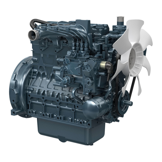
M0076814-03 Product Information Section Model Views Product Information Section Model Views i06822953 Model View Illustrations The following model views show typical features of the engine. Due to individual applications, your engine may appear different from the illustrations. Engine Views Illustration 13 g06134993 Typical example (1) Oil filler... - Page 19 M0076814-03 Product Information Section Model View Illustrations Illustration 14 g06135026 Typical example (10) Rear lifting eye (14) Coolant pump (19) Oil sample valve (11) Turbocharger (15) Oil cooler (20) Oil drain plug (12) Front lifting eye (16) ECM for aftertreatment (21) Flywheel (13) Water temperature regulator housing (17) Primary fuel filter/priming pump...
- Page 20 M0076814-03 Product Information Section Model View Illustrations The ECM (16) will be supplied loose. Aftertreatment System The aftertreatment items are supplied loose by Perkins. Clean Emission Module Illustration 15 g06044166 Typical example (1) Clean Emission Model (CEM) (4) DEF Injector...
- Page 21 (2) DEF heated line (3) DEF tank header (4) DEF pump filter i06823092 (5) DEF tank drain Product Description The Perkins 2506F-E15TA Industrial Engine has the following characteristics: • Four-stroke cycle • Mechanically actuated, electronically controlled fuel injection system • Turbocharged •...
- Page 22 ECM. The topic. electronic engine control system provides the following features: Aftermarket Products and Perkins • Engine speed governor Engines • Automatic air/fuel ratio control Perkins does not warrant the quality or performance of non-Perkins fluids and filters.
- Page 23 Product Description When auxiliary devices, accessories, or consumables (filters, additives, catalysts) which are made by other manufacturers are used on Perkins products, the Perkins warranty is not affected simply because of such use. However, failures that result from the installation...
-
Page 24: Product Identification Information
M0076814-03 Product Information Section Product Identification Information Product Identification Information i06823820 Plate Locations and Film Locations Illustration 20 g01403841 Serial number plate The following information is stamped on the serial number plate: engine serial number, engine model, and arrangement number. The engine information plate is on top of the valve cover near the middle of the engine. - Page 25 Record the information on the CEM and PETU serial level, and configuration ID code. This information plates. The information will be required by your may be needed by the Perkins distributor when Perkins distributor to identify replacement part inquiries are being made on the CEM.
-
Page 26: Operation Section
Alterations to the lifting eyes and/or the engine make the lifting eyes and the lifting fixtures obsolete. If alterations are made, ensure that proper lifting devices are provided. Consult your Perkins distributor for information regarding fixtures for proper engine lifting. - Page 27 5 degree tilt angle can be maintained. For most packages,Perkins recommended the spreader bar be set at 142 cm (56 inch). The lift hook locations should be approximately 25 mm (1 inch) from...
- Page 28 (1 PETU lifting eyes i06605082 Product Storage (Engine and Aftertreatment) Your Perkins distributor can help in preparing the engine for extended storage periods. Some applications, the engine can be equipped with delayed engine shutdown. Allow at least 2 minutes after the engine has stopped before you turn the battery disconnect switch to OFF.
- Page 29 M0076814-03 Operation Section Engine and Aftertreatment Engine Open the fuel tank drain valve to drain any water and dirt from the fuel tank. Apply a spray of 1. Clean the engine of any dirt, rust, grease, and oil. calibration fluid or kerosene at the rate of Inspect the exterior.
- Page 30 ISO 22241-1. (1) Plug 3. Ensure that all DEF lines and electrical connection 8. If an engine is stored for more than 1 year, Perkins are connected prior to prevent crystal from recommends Pre lubrication of the engine to avoid forming.
- Page 31 36 months remove connector and install plug (1). Tighten plug 25° C (77° F) 18 months to a torque of 30 N·m (265 lb in). Perkins recommends that the procedure must be 30° C (86° F) 12 months performed in a minimum ambient temperature of 35°...
-
Page 32: Features And Controls
M0076814-03 Operation Section Features and Controls Features and Controls Note: Some items have been removed from engine for clarity. i06163203 Monitoring System The monitoring system is designed to alert the operator to an immediate problem with any of the engine systems that are monitored. The monitoring system is also designed to alert the operator to an impending problem with any of the engine systems that are monitored. - Page 33 M0076814-03 Operation Section Sensors and Electrical Components Engine Illustration 30 g06130474 Typical example (1) Secondary Speed/timing sensor (6) NRS differential pressure sensor (11) Oil pressure sensor (2) Boost pressure sensor (7) NRS temperature sensor (12) Barometer pressure sensor (3) Inlet air temperature sensor (8) Air control solenoid valve (13) Fuel pressure sensor (4) NOx Reduction System (NRS) solenoid...
- Page 34 M0076814-03 Operation Section Sensors and Electrical Components Illustration 31 g06130477 Typical example (16) Coolant temperature sensor...
- Page 35 M0076814-03 Operation Section Sensors and Electrical Components Illustration 32 g06130480 Typical example (17) Location for Top Dead Center (TDC) probe Aftertreatment System Illustration 33 g06048751 Typical example (1) Diesel Exhaust Fluid (DEF) injector (3) Coil for spark plug (2) Temperature sensor...
- Page 36 M0076814-03 Operation Section Sensors and Electrical Components (4) Diesel Particulate Filter (DPF) differential (7) 40-Pin connector (10) Fuel main pressure sensor pressure sensor (8) Selective Catalytic Reduction (SCR) (11) Identification Module (5) DPF pressure sensor temperature sensor (12) Temperature sender for Aftertreatment (6) Temperature sender (9) Fuel pilot pressure sensor Regeneration Device (ARD)
- Page 37 M0076814-03 Operation Section Battery Disconnect Switch DEF header (1) contains level sensor temperature The battery disconnect switch and the engine start sensor and quality sensor. switch perform different functions. The entire electrical system is disabled when you turn the battery disconnect switch to the OFF position. The i05422613 battery remains connected to the electrical system when you turn the engine start switch to the OFF...
- Page 38 M0076814-03 Operation Section Selective Catalytic Reduction Warning System Safe Harbor Mode (European Union) – Safe NOTICE Harbor Mode is a 30 minute engine run time period Allow at least 2 minutes after shutting down the en- that the engine can be operated with full power after gine before you turn the battery disconnect switch to reaching a level 3 inducement.
- Page 39 M0076814-03 Operation Section Selective Catalytic Reduction Warning System Illustration 38 g03676111 Illustration 40 g03676127 If the DEF level falls below 13.5%, a level 1 Reduced Time inducement event will occur. The check engine lamp If the ECM is configured to “Reduced Time” and the and the emissions malfunction indicator lamp will DEF level is 0%, the engine will be in level 3 illuminate.
- Page 40 2. The check engine lamp and the emissions malfunction indicator lamp will illuminate Note: Contact your Perkins dealer for repairs if a fault and flash slowly. If the inducement is a result of a occurs.
- Page 41 M0076814-03 Operation Section Selective Catalytic Reduction Warning System Illustration 45 g03676169 Illustration 47 g03676210 If the DEF level falls below 13.5%, a level 1 If the ECM is configured to “Reduced Performance” inducement event will occur. The check engine lamp and the DEF tank has been emptied of all DEF, the and the emissions malfunction indicator lamp will engine will be in a level 3 final inducement.
- Page 42 For repeat occurrence, a category 1 level 2 inducement fault will occur for a Note: Contact your Perkins dealer for repairs if a fault duration of 5 minutes. occurs. If the inducement is a result of a category 2 fault, then a level 2 inducement will occur for a duration of 10 hours.
-
Page 43: Engine Diagnostics
Engine Diagnostics Engine Diagnostics i05194988 Self-Diagnostics Perkins Electronic Engines have the capability to perform a self-diagnostics test. When the system detects an active problem, a diagnostic lamp is activated. Diagnostic codes will be stored in permanent memory in the Electronic Control Module (ECM. -
Page 44: Engine Starting
M0076814-03 Operation Section Engine Starting Engine Starting • Do not start the engine or move any of the controls if there is a “DO NOT OPERATE” warning tag or similar warning tag attached to the start switch or i02109067 to the controls. Before Starting Engine •... - Page 45 M0076814-03 Operation Section Starting the Engine Starting the Engine Note: Oil pressures and fuel pressures should be in the normal range on the instrument panel. Engines that are equipped with “WARNING” lamps do not Refer to the Owners Manual of the OEM for your type of controls.
- Page 46 (Do Not Use This Procedure in 3. Start the engine. If the engine does not start, check Hazardous Locations that have for a diagnostic code and consult your Perkins distributor. Explosive Atmospheres) i04132731 Cold Weather Starting...
- Page 47 M0076814-03 Operation Section After Starting Engine 3. Connect one negative end of the jump-start cable to the negative cable terminal of the electrical source. Connect the other negative end of the Improper jump start cable connections can cause an explosion resulting in personal injury. jump-start cable to the engine block or to the chassis ground.
- Page 48 M0076814-03 Operation Section After Starting Engine Extended Idle at Cold Ambient Temperature The engine may automatically change speeds when the engine is idling in cold ambient temperatures (typically less than 0° C (32° F) for extended periods. The purpose of the automatic speed change is threefold: to maintain the desired operation of the NOx reduction system, to maintain the desired operation of the regeneration system and to keep the...
-
Page 49: Engine Operation
M0076814-03 Operation Section Engine Operation Engine Operation This design of DPF will require a service maintenance interval. Refer to this Operation and Maintenance Manual, “Maintenance Interval Schedule” for more information. The DPF can be i06603162 expected to function properly for the useful life of the engine (emissions durability period), as defined by Engine Operation regulation, subject to prescribed maintenance... - Page 50 M0076814-03 Operation Section Diesel Particulate Filter Regeneration Note: If the engine start switch key is cycled or the Disabled: When the regeneration system is in disabled mode, automatic regenerations will not be “Force Regeneration” switch is pressed for longer performed. The DPF indicator will illuminate if manual than 2 seconds the system will no longer be disabled.
- Page 51 M0076814-03 Operation Section Engaging the Driven Equipment If the soot load is above a threshold or “Time to NOTICE Regen” is 0 hours, then regeneration is required. The The engine and emissions control system shall be DPF indicator will illuminate and flash slowly. Engine operated, used, and maintained in accordance with power will be slightly derated.
- Page 52 Fuel Conservation Practices The efficiency of the engine can affect the fuel economy. Perkins design and technology in manufacturing provides maximum fuel efficiency in all applications. Follow the recommended procedures to attain optimum performance for the life of the engine.
-
Page 53: Engine Stopping
M0076814-03 Operation Section Engine Stopping Engine Stopping Leaving the machine unattended when the engine i05798719 is running may result in personal injury or death. Before leaving the machine operator station, neu- Stopping the Engine tralize the travel controls, lower the work tools to the ground and deactivate all work tools, and place the lever for the hydraulic lockout control in the LOCKED position. - Page 54 M0076814-03 Operation Section Manual Stop Procedure i01465494 After Stopping Engine Note: Before you check the engine oil, do not operate the engine for at least 10 minutes in order to allow the engine oil to return to the oil pan. •...
-
Page 55: Cold Weather Operation
• Fuel line insulation, which may be an OEM option could cause a fan failure. Winter and arctic grades of diesel fuel are available in Perkins recommends a warning device for the inlet the countries and territories with severe winters. For manifold temperature and/or the installation of an more information refer to the Operation and inlet air temperature gauge. - Page 56 37° C (100° F). Note: Heat exchanger type fuel heaters should have a bypass provision in order to prevent overheating of the fuel in warm-weather operation. For further information on fuel heaters, consult your Perkins distributor .
-
Page 57: Maintenance Section
Refill Capacities the most up-to-date recommendations. Diesel Fuel Requirements i07490664 Fluid Recommendations Perkins is not in a position to continuously evaluate and monitor all worldwide distillate diesel fuel (General Fuel Information) specifications that are published by governments and technological societies. - Page 58 M0076814-03 Maintenance Section General Fuel Information Table 3 "Perkins Specification for Distillate Diesel Fuel" Property UNITS Requirements “ASTM”Test “ISO/Other”Test Aromatics %Volume 35% maximum “D1319” “ISO 3837” %Weight 0.01% maximum “D482” “ISO 6245” Carbon Residue on 10% %Weight 0.20% maximum “D524”...
- Page 59 EPA and other appropriate regulatory agencies. NOTICE Operating with fuels that do not meet the Perkins rec- ommendations can cause the following effects: Start- ing difficulty, reduced fuel filter service life, poor combustion, deposits in the fuel injectors, signifi- cantly reduce service life of the fuel system.
- Page 60 Refer to the Recommendation for Biodiesel and Using B20 section of this “Operation and Maintenance Manual” Fluid Recommendations for more information. All the fuels must comply with the specification in the table for the Perkins Specification Distillate Diesel Fuel. Diesel Fuel Characteristics Perkins recommends kinematic viscosities of 1.4 and 4.5 mm2/sec that is delivered to the fuel injection...
- Page 61 Protection Agency (EPA) and European Certification wear scar diameter than 0.52 mm (0.0205 inch) will fuels. Perkins does not certify engines on any other lead to reduced service life and premature failure of fuel. The user of the engine has the responsibility of the fuel system.
- Page 62 Rancimant test), and sediment (ISO12937). For standby generator sets oxidation • Perkins recommend the use of oil analysis to stability of biodiesel blend must be 20 hours or more check the quality of the engine oil if biodiesel fuel as per EN 15751.
- Page 63 Paraffinic diesel fuels are considered as acceptable to use as a directed replacement to petroleum diesel operate incorrectly. or as a blendstock for petroleum diesel fuel in Perkins Contact your fuel supplier for those circumstances diesel engines provided they meet latest edition of when fuel additives are required.
- Page 64 • Perkins recommends the use of bulk fuel filter / Details instruction on the rate of which the fuel cleaner is to be used are on the container.
- Page 65 M0076814-03 Maintenance Section Fluid Recommendations Consult your local Perkins distributor for additional Note: The water must be used with an inhibitor to information on Perkins designed and produced protect the engine. filtration products. Distilled water or deionized water is recommended for use in engine cooling systems.
- Page 66 Until such standard/ • Boiling specifications are published and evaluated by Perkins, use of PDO, glycerine or other alternative • Freezing coolants is not recommended in Perkins diesel engines.
- Page 67 OEM to set the heater control. After the cooling agents with low amounts of nitrite. Perkins ELC has system is drained and the cooling system is refilled, been formulated with the correct amount of these...
- Page 68 An SCA that is liquid may be needed at 500 hour Perkins. intervals. NOTICE 6. Fill the cooling system with the Perkins Premixed Do not mix types and brands of coolant. ELC. Operate the engine. Ensure that all coolant valves open then stop the engine. When cool Do not mix brands and types of SCAs.
- Page 69 Use a non-foaming detergent to clean Example Of The Equation For Adding The SCA To The Heavy- Duty Coolant At The Initial Fill oil contamination, consult your Perkins dealer for suitable product. Total Volume of the Multiplication...
- Page 70 “EMA Recommended Guideline on Diesel Engine There is a small percentage of particulate matter that Oil”. In addition to Perkins definitions, there are other definitions that will be of assistance in purchasing is left behind as the soot is burnt. This matter will eventually block the filter, causing loss of lubricants.
- Page 71 Lubricant Viscosity Recommendations Aftermarket Oil Additives for Direct Injection (DI) Diesel Engines Perkins does not recommend the use of aftermarket additives in oil. Aftermarket additives are not The correct SAE viscosity grade of oil is determined necessary to achieve the engines maximum service by the minimum ambient temperature during cold life or rated performance.
- Page 72 M0076814-03 Maintenance Section Refill Capacities and Recommendations • The Oil Condition Analysis determines the loss of the oils lubricating properties. An infrared analysis is used to compare the properties of new oil to the properties of the used oil sample. This analysis allows technicians to determine the amount of deterioration of the oil during use.
-
Page 73: Maintenance Recommendations
Consult the OEM of the equip- To relieve the pressure from the coolant system, turn ment or your Perkins dealer regarding welding on a off the engine. Allow the cooling system pressure cap chassis frame or rail. - Page 74 (2) Welding electrode Refer to the standards for the engine or consult your (3) Keyswitch in the OFF position Perkins distributor to determine if the engine is (4) Battery disconnect switch in the open position operating within the defined parameters.
- Page 75 Severe Service Application Due to individual applications, identification is not possible for all the factors which can contribute to severe service operation. Consult your Perkins distributor for the unique maintenance that is necessary for the engine. The operating environment, incorrect operating...
-
Page 76: Maintenance Interval Schedule
M0076814-03 Maintenance Section Maintenance Interval Schedule “ Belts - Inspect/Replace” ....83 i07509666 Maintenance Interval Schedule “ Cooling System Supplemental Coolant Additive (SCA) - Test/Add”... - Page 77 M0076814-03 Maintenance Section Maintenance Interval Schedule “Diesel Exhaust Fluid Injector (Emission Related Component) - Replace” ..... . 94 Every 6000 Service Hours or 3 Years “...
- Page 78 M0076814-03 Maintenance Section ARD Spark Plug (Emission Related Component) - Clean 2. Debris may have collected in the spark plug well. i07508570 Thoroughly remove any debris. Use compressed ARD Spark Plug (Emission air. The maximum air pressure for cleaning Related Component) - Clean purposes must be below 205 kPa (30 psi).
- Page 79 All personnel should also stay clear of the air compressor when the engine is operating and the air compressor is exposed. Consult your Perkins distributor for assistance. Do not disconnect the air line from the air com- pressor governor without purging the air brake i00847451 and the auxiliary air systems.
- Page 80 M0076814-03 Maintenance Section Battery - Replace • An authorized battery collection facility 7. Connect the cable from the starting motor to the POSITIVE “+” battery terminal. • A recycling facility 8. Connect the cable from the NEGATIVE “-” terminal on the starter motor to the NEGATIVE “-” battery i01878164 terminal.
- Page 81 M0076814-03 Maintenance Section Battery or Battery Cable - Disconnect i05424317 i06940875 Battery or Battery Cable - Belts - Inspect/Adjust/Replace Disconnect (Vee Belt General Information) The information within this section may be used as a guide to adjust the tension of the belt. If the Original Equipment Manufacture (OEM has installed the belt The battery cables or the batteries should not be system, then refer to OEM information.
- Page 82 M0076814-03 Maintenance Section Vee Belt General Information Link adjuster Rod adjuster Illustration 64 g06108813 Illustration 65 g06109400 Typical example Typical example 1. Remove guards, refer to the OEM for the correct 1. Remove the belt guard, refer to OEM for the procedure.
- Page 83 M0076814-03 Maintenance Section Belts - Inspect/Replace Fan Belt Adjustment To replace the fan belts, refer to Disassembly and Assembly, V-Belts- Remove and Install. Belt Tension Table 16 Alternator and Fan Belt Tension Belt Type Belt Size New Belt Used Belt Reset Belt Tension Tension...
- Page 84 M0076814-03 Maintenance Section Cooling System Coolant (DEAC) - Change To maximize the engine performance, inspect the belt for wear and for cracking. Replace the belt if the belt is worn or damaged. • Inspect the belt for cracks, splits, glazing, grease, displacement of the cord and evidence of fluid contamination.
- Page 85 M0076814-03 Maintenance Section Cooling System Coolant (DEAC) - Change NOTICE Fill the cooling system no faster than 19 L (5 US gal) per minute to avoid air locks. 3. Fill the cooling system with clean water and operate the engine, ensure that the thermostat opens.
- Page 86 Cooling System Coolant (ELC - Change NOTICE Perkins ELC must be using with an extender in order to achieve 12000 hours operation. For more informa- tion on a suitable extender contact your Perkins distributor. Clean the cooling system and flush the cooling...
- Page 87 49 °C to 66 °C (120 °F to 150 °F). For Perkins ELC to achieve 12000 hours an extender must be added at 6000 hours. For a suitable 5. Stop the engine and allow the engine to cool.
- Page 88 M0076814-03 Maintenance Section Cooling System Supplemental Coolant Additive (SCA) - Test/Add Use a Coolant Conditioner Test Kit in order to check the concentration of the SCA. Add the SCA, If Necessary NOTICE Do not exceed the recommended amount of supple- mental coolant additive concentration.
- Page 89 M0076814-03 Maintenance Section DEF Filler Screen (Emission Related Component) - Clean 4. Clean the cooling system filler cap and inspect the 2. Using a suitable tool, press the tabs (2) in order to gasket. If the gasket is damaged, discard the old release the tabs.
- Page 90 M0076814-03 Maintenance Section DEF Manifold Filters (Emission Related Component) - Replace Illustration 74 g03806578 Illustration 75 g03806580 2. Remove band clamp (2) from filter base (1). 3. Remove filter (3) from filter base (1).
- Page 91 M0076814-03 Maintenance Section DEF Manifold Filters (Emission Related Component) - Replace Illustration 76 g03806581 Illustration 78 g06159487 1. Note the location of clamp (2). The clamp (2) must be between the marked location (A). 2. Loosen clamp (2) and remove outer filter (3) from DEF tank header (1) and discard outer filter (3).
- Page 92 M0076814-03 Maintenance Section Diesel Exhaust Fluid (Emission Related Component) - Fill 6. Install the retaining plate (6) and install screws (7). Caution should be used when dispensing DEF near an engine that has recently been running. Spilling Tighten screws (7) to a torque of 1.1 N·m DEF onto hot components may cause the release of (9.8 lb in).
- Page 93 M0076814-03 Maintenance Section Diesel Exhaust Fluid Filter (Emission Related Component) - Replace Illustration 81 g03332612 Illustration 82 g03332637 Typical Example Typical Example 3. Insert the DEF filter removal tool (4) into the DEF filter (1) and remove the DEF filter (1). Personal injury can result from improper han- Note: Avoid twisting the DEF filter (1) upon removal.
- Page 94 (Emission Related • Easy detection of fluid leaks • Maximum heat transfer characteristics Consult your Perkins distributor when the diesel particulate filter needs to be cleaned for the options • Ease of maintenance that are available. The ash monitoring system within the electric control...
- Page 95 Servicing the Air Cleaner Element Note: The air filter system may not have been provided by Perkins. The procedure that follows is for Illustration 84 g06043462 a typical air filter system. Refer to the OEM Typical example information for the correct procedure.
- Page 96 Illustration 85 g00103777 recommended torques. Typical service indicator When the engine mounts are supplied by Perkins the maintenance procedure will be supplied in the Observe the service indicator. The air cleaner element should be cleaned or the air cleaner element Disassembly and Assembly manual for your engine.
- Page 97 The condition of the engine lubricating oil may be checked at regular intervals as part of a preventive (Y) “ADD” mark maintenance program. Perkins include an oil (X) “FULL” mark sampling valve as an option. The oil sampling valve (if equipped) is included in order to regularly sample NOTICE the engine lubricating oil.
- Page 98 M0076814-03 Maintenance Section Engine Oil and Filter - Change Perkins recommends using a sampling valve in order The sample can be checked for the following: the to obtain oil samples. The quality and the consistency quality of the oil, the existence of any coolant in the...
- Page 99 Perkins oil filters are manufactured to Perkins specifi- local regulations. cations. Use of an oil filter that is not recommended by Perkins could result in severe damage to the en- Fill the Oil Pan gine bearings, and crankshaft. As a result of the larg- er waste particles from unfiltered oil entering the 1.
- Page 100 Special Precautions housing. Alternately, empty and reinstall the spin- on fuel filter element to remove any dirt and water. Your Perkins distributor can help in preparing the Drain any sleeve metering fuel pump. engine for extended storage periods. Clean the primary fuel filter. Fill with calibration Some applications, the engine can be equipped with fluid or kerosene.
- Page 101 M0076814-03 Maintenance Section Engine Storage Procedure - Check Use a bar or a turning tool to turn over the engine Refer to this Operation and Maintenance Manual, “Fluid Recommendations” for more information about slowly. This procedure puts the oil on the cylinder coolants.
- Page 102 1. If necessary, drain the tank and fill with DEF that meets ISO 22241-1. 8. If an engine is stored for more than 1 year, Perkins 2. Replace the DEF filter, refer to this Operation, and recommends Pre lubrication of the engine to avoid Maintenance Manual, “Diesel Exhaust Fluid Filter-...
- Page 103 NOTICE Only qualified service personel should perform this maintenance. Refer to the Service Manual or your au- thorized Perkins dealer or your Perkins distributor for the complete valve lash adjustment procedure. Operation of Perkins engines with incorrect valve lash can reduce engine efficiency, and also reduce engine component life.
- Page 104 M0076814-03 Maintenance Section Fuel System Primary Filter (Water Separator) Element - Replace 5. If the engine starts and the engine runs rough or the engine misfires, operate at low idle until the engine is running smoothly. If the engine cannot be started, or if the engine continues to misfire or smoke, repeat Step 2.
- Page 105 M0076814-03 Maintenance Section Fuel System Primary Filter/Water Separator - Drain i06616051 i06605835 Fuel System Primary Filter/ Fuel System Secondary Filter - Water Separator - Drain Replace Fuel leaked or spilled onto hot surfaces or electri- Fuel leaked or spilled onto hot surfaces or electri- cal components can cause a fire.
- Page 106 M0076814-03 Maintenance Section Fuel Tank Water and Sediment - Drain i02348492 Fuel Tank Water and Sediment - Drain NOTICE Care must be taken to ensure that fluids are con- tained during performance of inspection, mainte- nance, testing, adjusting and repair of the product. Be prepared to collect the fluid with suitable contain- ers before opening any compartment or disassem- bling any component containing fluids.
- Page 107 M0076814-03 Maintenance Section Grounding Stud - Inspect/Clean/Tighten Some fuel tanks use supply pipes that allow water The grounding stud must have a wire ground to the and sediment to settle below the end of the fuel battery. Tighten the grounding stud at every oil supply pipe.
- Page 108 The following text describes a typical method of replacing coolant hoses. Refer to the OEM information for further information on the coolant system and the hoses for the coolant system. For an overhaul solution, contact your Perkins distributor. i03901481 Pressurized System: Hot coolant can cause seri- Power Take-Off Clutch - Check ous burns.
- Page 109 Starting Motor - Inspect i08254039 Radiator - Clean Perkins recommends a scheduled inspection of the starting motor. If the starting motor fails, the engine may not start in an emergency situation. Check the starting motor for proper operation. Check...
- Page 110 Service Manual for the engine or consult your Perkins distributor . • Inspect the lubrication system for leaks at the front crankshaft seal, the rear crankshaft seal, the oil...
-
Page 111: Warranty Section
(“emission-related components”), are: For a detailed explanation of the Emission Control Warranty, contact your authorized Perkins dealer or a. Designed, built, and equipped so as to conform, your authorized Perkins distributor. at the time of sale, with applicable emission... -
Page 112: Reference Information Section
• Establish maintenance schedules for other repair cost (parts, labor, and travel). engines that are operated in the same environment. 2. Enjoy longer lasting product support from Perkins global network. • Show compliance with the required maintenance practices and maintenance intervals. - Page 113 M0076814-03 Reference Information Section Maintenance Log unit number and engine serial number. The following types of documents should be kept as proof of maintenance or repair for warranty: Keep the following types of documents as proof of maintenance for warranty. Also, keep these types of documents as proof of repair for warranty: •...
- Page 114 M0076814-03 Reference Information Section Maintenance Log (Table 18, contd)
-
Page 115: Index
M0076814-03 Index Section Index Flush ............86 Cooling System Coolant Extender (ELC) - Additional Messages ......... 7 Add ..............87 After Starting Engine ........47 Cooling System Coolant Level - Check... 87 Extended Idle at Cold Ambient Cooling System Supplemental Coolant Temperature.......... - Page 116 M0076814-03 Index Section Servicing the Air Cleaner Element ....95 California Proposition 65 Warning ....4 Engine Air Cleaner Service Indicator - Literature Information ........4 Inspect (If Equipped) ........96 Maintenance ..........4 Test the Service Indicator ......96 Maintenance Intervals ........
- Page 117 Aftertreatment System......... 35 Power Take-Off Clutch - Check..... 108 Engine............33 Product Description ......... 21 Pump Electronic Tank Unit (PETU) ..... 36 Aftermarket Products and Perkins Severe Service Application ......74 Engines ............22 Environmental Factors......... 75 Electronic Engine Features ......22 Incorrect Maintenance Procedures .....
- Page 118 M0076814-03 Index Section Locations that have Explosive Atmospheres) ..........46 Stopping the Engine ........53 Delayed Engine Shutdown (If Enabled) ..53 System Pressure Release....... 73 Coolant System ........... 73 Engine Oil ............ 73 Fuel System..........73 Table of Contents ..........3 Walk-Around Inspection .........110 Inspect the Engine for Leaks and for Loose Connections ..........110...
- Page 119 Product and Dealer Information Note: For product identification plate locations, see the section “Product Identification Information” in the Operation and Maintenance Manual. Delivery Date: Product Information Model: Product Identification Number: Engine Serial Number: Transmission Serial Number: Generator Serial Number: Attachment Serial Numbers: Attachment Information: Customer Equipment Number: Dealer Equipment Number:...
- Page 120 M0076814 ©2020 Perkins Engines Company Limited All Rights Reserved December 2020...
Need help?
Do you have a question about the 2506J-E15TA and is the answer not in the manual?
Questions and answers